

Cell Biology Protocols
.pdfPROTOCOL 1.1
Setting up the microscope for bright field microscopy
1.Set up the microscope on a clean, dry area of bench as vibration-free as possible.
2.Plug in and switch on the illuminator.
3.Centre and focus the light source according to the manufacturer’s instructions. The light source on many microscopes is precentred.
4.Bring the ×10 objective into position on the nosepiece and ensure the condenser is in the bright field position, usually indicated by a zero (0).
5.Fully open the field diaphragm on the light source and the aperture diaphragm of the condenser.
6.Adjust the brightness of the light from the illuminator to a comfortable level using the rheostat.
7.Place a clean, prepared slide on the stage. Use a stained preparation or section. Bring the objective to within a few millimetres of the coverslip on the slide. Make sure that the specimen is in line with the objective.
8.Looking through the eyepieces gently lower the stage by rotating the course adjustment until the specimen appears in focus. Move through the focal position: continue rotating the knob until the specimen has appeared in focus, and is just beginning to become blurred again.
9.Now use the fine adjustment to make the image clear.
10.Adjust the interpupillary distance between the eyepieces so that it is comfortable for you.

PROTOCOL 1.2
Setting Kohler¨ illumination
To focus the condenser and set up Kohler¨ illumination:
1.Gently rack the condenser upwards to the top of its travel.
2.Close down the field iris diaphragm of the illuminator. Focus the image by lowering the condenser. The condenser is focused when both the specimen and the diaphragm edge are sharply defined.
3.Centre the field diaphragm image into the centre of the field of view, using the centring screws on the condenser, then open the field diaphragm to just fill the field of view.
4.Remove one eyepiece and, looking into the tube, adjust the condenser aperture diaphragm so that it covers two-thirds to three-quarters of the circular illuminated area. This controls the angle of the cone of light illuminating the object and helps avoid flare.
5.Replace the eyepiece; Kohler¨ illumination is now set up. The brightness of the field should be altered by adjusting the light intensity of the illuminator. Do not alter light by adjusting the condenser or field diaphragm.
6.The alignment should be correct for all objectives. The nosepiece can be rotated
to bring other objectives into position. Most microscopes are parfocal so only the fine focus should be used to make final adjustments to obtain clear images.
Use of oil immersion objectives
Oil immersion objectives are objectives that are used with immersion oil (instead of air) in the space between the front lens of the objective and the coverslip. As explained previously, this method leads to a gain in NA, and hence a gain in the resolution, brightness and clarity of the image. Immersion oil has a refractive index of 1.515 and glass has a refractive index of 1.51. The principles underlying the use of the ×100 objective are similar to those used in setting up the lower power objectives. The only differences, in practice, are the introduction of an oil film between the top of the coverslip and the objective lens and the need for very great caution in focusing because of the very short working distance of ×100 objectives.
When examining extremely small specimens, such as bacteria and individual eukaryote cells, locating the sample image can be difficult. It is easiest to focus on the sample first using the ×40 objective. Then, using the fact that the objectives are parfocal, move to the ×100 objective.

PROTOCOL 1.3
Focusing procedure
1.Focus on the specimen using the ×40 objective (in some cases, you may wish to start with an even lower power objective first).
2.Move the ×40 objective away from the
slide, but do not yet move the revolving nosepiece fully round to bring the ×100 objective into position.
3.Leaving the slide in position on the stage, apply a small drop of immersion oil onto the illuminated spot on the coverslip. Do not use too much oil, it can run off the slide and on to the microscope.
4.Carefully move the ×100 objective into position, checking that there is space for it. The objective should make contact with the oil, but not the slide.
5.You should be approximately in focus already so only use the fine focus knob.
Oil immersion objectives and slides which have been used with oil should always be cleaned with lens tissue immediately after use. If left uncleaned the oil tends to dry up and may form a hard film on the objective and slide.
Phase contrast microscopy
If a typical living cell is observed under well-aligned bright field microscopy, very little detail can be observed. However, small differences in the refractive indices or the thickness within specimen structures can be converted into differences of light and dark. This is what is known as phase contrast microscopy and it is extensively used for observing living and unstained specimens.
In the phase contrast optics there is a phase ring in the rear focal plane of the objective and a phase annulus in the front focal plane of the condenser (Figure 1.4A). The ring and the annulus alter the amplitude and phase relationships of the light diffracted by structures in the cell compared to the non-diffracted light to generate interference, thereby enhancing contrast. Phase contrast produces an image of many dark and light grey gradations. Positive phase contrast areas with higher refractive indices, like mitochondria in the cytoplasm and nucleoli against the background of the nucleoplasm, appear darker.
Phase contrast microscopy is limited to thin specimens, single cells or very thin cell layers. The resolution is also limited by the phase ring and phase annulus.

10 BASIC LIGHT MICROSCOPY
(a)
Side view of phase ring in objective
Objective
Specimen on slide
Condenser
Side view of phase
annulus in the condenser 

(b)
Phase ring as seen down the centring telescope
Phase annulus as down the centring telescope
Phase ring
Phase annulus
(i) |
(ii) |
Figure 1.4 Phase contrast. (a) the light path in a phase contrast microscope showing the phase ring in the objective and the phase annulus in the condenser. (b) Incorrect (i) and correct (ii) alignment of the phase ring and phase annulus

PROTOCOL 1.4
Setting up the microscope for phase contrast microscopy
1.The objectives for phase microscopy are different from those used for brightfield only. They include a phase ring and are usually inscribed Ph. Phase contrast objectives can also be used for bright field work. The condenser is also different; it contains a series of phase annulae.
2.Kohler¨ illumination is set up as described previously
3.To centre the phase contrast annular diaphragm, start with the objective ×10 Ph 1. Set the condenser turret to the appropriate position.
4.Move the specimen slide to a position where no object is seen, yet the coverslip is still present.
5.Remove the eyepiece and in its place insert the centring telescope (phase telescope). Rotate the top part of the telescope to bring the image of the phase plate in the objective into sharp focus. The image of the condenser annulus will also be visible.
6.The position of the objective phase ring is fixed but the phase annulus in the condenser can be moved by manipulating the adjusting screws on the condenser. The phase annulus needs to be superimposed, concentrically, over the phase ring (see Figure 4B).
With many microscopes the phase annulae in the condenser turret are adjusted taking ×10 Ph 1 as the standard so it may not
be necessary to perform the centring procedure at each magnification. However, for ideal resolution and for photomicrography it is advisable to check the centring at each magnification.
Differential interference contrast microscopy
This is another type of interference system that detects very small gradients or differences in thickness or refractive index. It is based on illumination of the specimen with two beams of light polarized at 90◦ to each other and with a lateral displacement (shear) of approximately the resolution limit of the objective. By altering the special beam-splitting prisms one can obtain an almost continuous change from bright field to dark field microscopy resembling degrees of highly oblique illumination and giving a three-dimensional appearance. Like phase contrast microscopy, this method is used to reproduce unstained transparent objects at high contrast. The image obtained gives a characteristic relief effect and offers some advantage over ordinary phase contrast optics. It is particularly useful for the study of dynamic events in vivo, for example cells in mitosis, and for studying the three-dimensional structure of cells and embryos.
Dark field microscopy
Dark field microscopy can be employed in the study of living micro-organisms
12 BASIC LIGHT MICROSCOPY
such as spirochetes, protozoa and yeast and unstained tissues and cells.
In bright field microscopy stains are used to produce sufficient contrast in the specimen so that diffraction can occur, thus rendering the specimen detail visible. Staining, however, can produce artifactual changes in some biological specimens; also fixation prior to staining kills the cell. Therefore, dark field microscopy, like phase contrast, is very useful for the study of living specimens. With dark field microscopy sufficient contrast can be introduced between a transparent object and the surrounding medium to render the object visible. This is done by illuminating the object at such an oblique angle that intense rays of light that normally pass through the specimen and travel directly into the objective (illuminating the entire field of view) are directed past the objective. This produces a dark field of view but the contrast between the dark background and the diffracted rays scattered off the specimen renders the object visible, bright and shiny against the dark background.
Although bright field condensers can be adjusted to give an approximation of a dark field, special condensers produce the required hollow cone of light more effectively.
Of great importance when using dark field techniques is the extreme cleanliness of slides, coverslips and immersion substances. Air bubbles, dirt or any extraneous material will be refractile and therefore interfere with the image from the specimen.
Fluorescence microscopy
Fluorescence microscopy is a sensitive technique very widely used in both research and clinical laboratories. Some materials for microscopic examination are autofluorescent, e.g. lipids, vitamins, porphyrins, drugs and drug-containing tissues
and carcinogenic compounds. In addition fluorescent dyes are used to stain cells and tissues. There are now a wide range of fluorescent labels for a large number of physiologically important biological molecules. Secondary fluorescence is also of major importance. This is obtained by such methods as immunofluorescence, whereby a biological molecule is located by using an antibody joined to a fluorochrome dye or when fluorescent probes attached to oligonucleotides are used to identify genes on chromosomes.
An atom or molecule, when struck by a quantum of light, undergoes a change in the arrangement of the electrons about its nucleus. The electron (or electrons) is displaced to a higher energy level in the form of heat and light. Since some of the energy is lost to heat, the light energy emitted is of a lower energy level and thus of a longer wavelength than the light that energized it. Therefore, when light of a short wavelength is directed towards a fluorochrome dye conjugate, the dye will emit radiation of a longer wavelength plus heat. By blocking out the exciting light ray, the emitted light rays can be isolated and detected by the eye through the microscope. The only difference between basic bright field microscopy and fluorescence microscopy is the use of an illumination system which produces only light of a shorter wavelength and a receiving system which receives only light of a longer wavelength.
In addition to the light source (usually a mercury or xenon lamp), a fluorescence microscope requires excitation and barrier filters. The excitation or primary filter will transmit shorter wavelength radiation only, while the barrier or secondary filter will transmit the longer wavelength emitted fluorescent light only. In order to obtain the best possible contrast, with bright specimen portions where fluorescence occurs and the darkest possible

background where there is no fluorescence, the most commonly used condenser system is a dark field condenser.
Most contemporary fluorescent microscopes use epifluorescence or incidentlight fluorescence. In these microscopes the objective also works as a condenser carrying the exciting beam and also collecting the emitted light. The assembly of filters in the filter block include the excitation filter and the barrier filter (interference filters) and a chromatic beam splitter (Figure 1.5). The microscope is relatively easy to align and it allows the use of thicker specimens and also the combination of the incident-light fluorescence excitation with a transmitted-light technique such as phase contrast.
PROTOCOL 1.4 |
13 |
Eyepiece
Lamp
Figure 1.5 Filter and dichroic mirror block in an epifluorescence microscope

PROTOCOL 1.5
Setting up the microscope for epifluorescence
The alignment |
of the light source |
to achieve an |
evenly illuminated field |
is critically important in epifluorescent microscopy:
1.Turn on the lamp and allow to warm up.
2.Insert the filter block to be used.
3.Place a white piece of paper on the
stage and adjust the light intensity to a suitable level with the slider. Open the condenser diaphragm and the field diaphragm.
4.Adjust the lamp collector focusing until a sharply focused image of the lamp is seen. Centre the image with the lamp centring screws.
5.Focus on a specimen slide. Close down the field diaphragm until it can be seen, focus the condenser and centre it using the centring screws on the condenser. When focused and centred open up the iris to the edge of the field of view.
Confocal microscopy
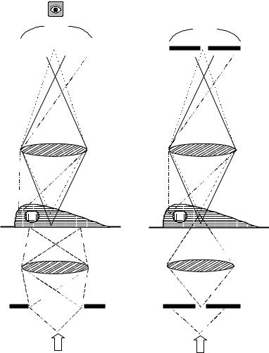
The resolution of fluorescence microscopy is limited by light emitted from above and below the focal plane leading to considerable blurring of the image. Confocal microscopy is intended to achieve a high axial resolution, that is structures in the centre of a cell can be distinguished from those at the top or the bottom. Contrary to conventional microscopy, it relies on point illumination, rather than field illumination. A schematic diagram of the corresponding configurations is shown in
Figure 1.6. The specimen is illuminated by a point source, consisting of a laser beam focused through a small aperture. Hence, the intensity reaching out-of-focus points on the specimen is lower than using conventional, field illumination. In turn, fluorescent light leaving the specimen is focused on the small detector aperture. As can be seen in Figure 1.6, the combined effects of point illumination, together with point detection, mean that most of the out- of-focus light is excluded from the final image, considerably increasing the contrast and therefore the fine detail of the sample.
The chromatic beam splitter reflects the excitation light towards the specimen, while allowing the emission light to reach the detector. The optical path from the source aperture to the objective lens is essentially the same as that from the objective lens to the detector aperture. Therefore, both the illuminating and detector apertures are focused on the illuminated point in the specimen and this is the reason why the system is called confocal. The detector is a photomultiplier (PMT), because the signal to be detected is usually very weak.
In a confocal system only a single point is viewed at a time. Therefore, in order to build an image, that point has to be scanned over the sample and the measured intensities recorded. This is usually achieved by scanning the beam using two mirrors, giving rise to the name confocal laser scanning microscopy (CLSM). Measured intensities are recorded and displayed by a host computer, which also
PROTOCOL 1.5 |
15 |
Wide field |
Confocal |
|||
|
|
Detector |
|
PMT |
|
|
|
|
|
|
|
|
|
|
|
|
|
|
|
Pinhole
Objective lens
Cell
Condenser lens
Pinhole
Light source
A B
Figure 1.6 Comparison of the light path in conventional (wide field) microscopy with that in confocal microscopy
drives the scanning system. All the thin sections along the axis obtained are largely devoid of out-of-focus light, this effect being called optical sectioning, and repetition of the X –Y scanning along the Z axis allows the construction of a 3-D image of the object being analysed. Projection of all Z sections over a single plane (maximum projection) results in a 2-D image which, unlike conventional microscopy, contains only in-focus information; thus a
large depth of field is achieved by adding together very thin, in-focus sections.
For optimum image acquisition, three elements have to be combined: the laser intensity, the size of the confocal aperture and the gain of the amplifier. Any increase of these parameters produces a bright image, but the effect may be detrimental on the image quality by reducing the resolution or increasing image noise or photobleaching. Table 1.3 summarizes

16 |
BASIC LIGHT MICROSCOPY |
|
|
|
|
|
Table 1.3 Factors affecting image collection in confocal microscopy |
||
|
|
|
|
|
Effect on: |
Laser intensity |
Aperture |
Gain |
|
|
|
|
|
|
Resolution |
Not affected, but high |
Closing the aperture |
Not affected directly but |
|
|
|
intensity allows for |
increases the |
through the control of |
|
|
smaller aperture |
resolution and the |
noise |
|
|
|
Z-sectioning effect |
|
Image noise |
Not directly affected, but |
|
high intensity allows |
|
for lower gain |
Photobleaching |
Higher intensity |
|
produces higher |
|
photobleaching |
Not directly affected, but |
Raising the gain |
large aperture allows |
introduces more noise |
for lower gain |
|
Not affected |
Not affected |
the effects of these components on the collected image.
Common problems and microscope care and maintenance
Problems in light microscopy usually arise from misalignment or dirt on the optical surfaces. Dark image and uneven illumination usually mean that the condenser is not correctly centred or the condenser diaphragm or field diaphragm are closed down too much or off-centre. The opposite can also occur with the image visible, but pale and undefined; this usually means that too much light is coming through and causing flare. The field or condenser diaphragms need to be closed down and the condenser adjusted. Dirt on the eyepieces or the objective will cause blurring and loss of definition. Dust on the lenses should be blown away with dry air and the lens cleaned with lens tissue moistened with distilled water. Stubborn grease can be removed with xylol; alcohols may dissolve the lens cement. Immersion oil should be wiped off at the end of every session of microscope use with lens tissue; never let the immersion oil dry to form a hardened film. Immersion oil should not be allowed to come into contact with any lenses except the oil immersion objective, but it is surprising how often a
film of oil is found on low and medium power objectives. This should be cleaned off as for the oil immersion objectives. Care should be taken not to scratch the lens surfaces.
Care should also be taken to ensure that the tubes of the microscope are closed either by an eyepiece or a dust plug. Similarly all positions on the revolving nosepiece should also be closed with a dust plug.
The rackwork and other moving parts should be treated with great care; it is essential not to force anything if it is apparently jammed. Do not apply grease of an unspecified type to the sliding surfaces of the course-focusing adjustment or the gliding stage.
At all times the instrument should handled carefully; for example, when carrying the microscope hold the base with one hand and the body with the other. When not in use the microscope should always be protected by a vinyl dust cover or kept in a cabinet.
Preparation and staining of specimens
Attachment
When working with tissue culture cells or cell smears, the cells to be stained need to