

page 15
DI:7. CONCEPTUAL DESIGN
•The first creative stage of any design is to generate concepts such as the choice between gasoline or electric powered vehicles.
•The most important rule in conceptual design is generate a few concepts and then select the best.
DI:7.1 GENERATION OF CONCEPTS
•This is the typically the hardest part of design.
•When talking about invention - this is the ‘inspiration’
DI:7.1.1 Brain Storming
•Basically this method generates a large number of diverse concepts using a group.
•One approach might be,
1.Have a meeting individuals (6-12 is good) related to the design tasks.
2.Make it clear that criticism is not allowed and every idea is good.
3.Ask everyone to write ideas on separate pieces of paper.
4.Start going round the room one at a time, and ask for the ideas. (Don’t allow criticism or judgement!) After the idea is given, the paper is placed in the center of the table.
5.This continues until all ideas are exhausted. (Participants should generate new ideas based on what they have heard from others). Encourage participants to suggest ridiculous ideas.
6.Go through the ideas in the middle of the table, and vote for the best one(s).
DI:7.1.1.1 - Practice Problems
1. Use brain storming to develop concepts for putting on shoes.
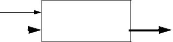
DI:7.1.2 Diagramming
• We can break functions down to subfunctions shown as black boxes
page 16
•Basically we draw functional blocks that show interfaced systems and indicating inputs and outputs of information, energy and materials.
•We can start by drawing one main box for a function (e.g., ‘a pen must draw a consistent line width)
Step 1: |
Writer |
Pen |
Paper |
Mechanical energy |
|
|
|
|
|
|
|
|
|
|
|
|
|
|
|
|
Mechanical energy |
||||||||||
Velocity |
|
|
|
|
|
|
|
|
|
|
|
|
|
|
|
|
|
|
|
|
|
|
|
Velocity |
|||
|
|
|
|
|
|
|
|
|
|
|
|
|
|
|
|
|
|
|
|
|
|
||||||
Ink |
|
|
|
|
|
|
|
|
|
|
|
|
|
|
|
|
|
|
|
|
|
|
Ink |
||||
|
|
|
|
|
|
|
|
|
|
|
|
|
|
|
|
|
|
|
|
|
|||||||
Line width |
|
|
|
|
|
|
|
|
|
|
|
|
|
|
|
|
|
|
|
|
|
|
Line width |
||||
|
|
|
|
|
|
|
|
|
|
|
|
|
|
|
|
||||||||||||
|
|
|
|
|
|
|
|
|
|
|
|
|
|
|
|
|
|
|
|
|
|
|
|
|
|
|
|
|
|
|
|
|
|
|
|
|
|
|
|
|
|
|
|
|
|
|
|
|
|||||||
|
Note: the lines indi- |
|
|
|
|
|
|
|
energy flow |
|
|||||||||||||||||
|
|
|
|
|
|
|
|
material flow |
|
||||||||||||||||||
|
|
|
|
cate different |
|
|
|
|
|
|
|
|
|
||||||||||||||
|
|
|
|
|
|
|
|
|
|
|
|
||||||||||||||||
|
|
|
|
flows. |
|
|
|
|
|
|
|
information flow |
|
||||||||||||||
|
|
|
|
|
|
|
|
|
|
|
|
|
|
|
|
|
|
|
|
||||||||
|
|
|
|
|
|
|
|
|
|
|
|
|
|
|
|
|
|
|
interfaced systems |
|
|||||||
|
|
|
|
|
|
|
|
|
|
|
|
|
|
|
|
|
|
|
|
||||||||
|
|
|
|
|
|
|
|
|
|
|
|
|
|
|
|
|
|
|
|
|
|
|
|
|
|
|
|
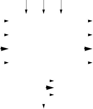
•The rules of thumb when creating the main diagrams are,
-pick reasonable function boundaries (not too much or too little)
-conserve energy and material
-indicate interfacing/involved parts of the system
-add information flows to determine how well the system is performing
•(as with IDEF) we can break the main function into sub functions. To do this we,
-make sub function boxes that show how
-create as many boxes as possible
-list alternates
-make sure all applicable flows are included
-consider sequences
-use standard notations
-use available documents, parts, etc to develop ideas
-don’t be afraid to add new items not on the first diagram
page 17
Step 2:
tip velocity
wet pen tip
ink in pen |
|
ink on tip |
|
|
|
• We can then combine the function blocks into a single diagram.
STEP 3:
• Finally, we convert the diagram to a conceptual design. The functional diagram(s) are used to provide clues, and in many cases they will lead directly to a design.
STEP 4:
DI:7.1.2.1 - Practice Problems
1.Considering the example started in the notes,
a)develop more subfunction blocks for the pen
b)using the previous blocks, draw a detailed functional diagram
c)Develop a final pen design using the final diagram.