

page 96
3. If a cutting plane cuts through intersecting features, the less important feature may be omitted for clarity, or to save time. For example, two rounds that intersect at an angle other than 90° would have an unusual shape, if one is not drawn, the section becomes much easier to do.
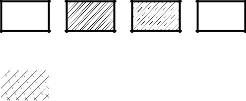
DI:14.1.6.11 - Fill Patterns
•Sections can be filled with a number of patterns to indicate different materials
•This was a common technique in the past. Some examples are given below.
cast iron and |
steel and |
bronze, brass |
zinc, lead, |
malleable iron |
wrought iron |
copper |
alloys |
|
|
|
|
|
|
|
|
aluminum and magnesium and their alloys
DI:14.1.7 Auxiliary Views
•The glass box can also be folded at odd angles. This technique produces views known as Auxiliary views.
•These views are useful when we want to draw a view of a surface that is not normal to one of the primary viewing planes.
•common terms used for this method are true size, and true shape. keep in mind that if a feature does not lie parallel to one of the primary viewing planes, it will appear distorted in every view.
•These views can be constructed from any view in a drawing. typical names for these identify the
page 97
view that they are drawn from,
-front auxiliary view
-top auxiliary view
-side auxiliary view
•We can also use auxiliary views to project other views for geometric purposes
•hidden lines are typically not used in auxiliary views, unless needed for clarity. Also, a number of surfaces are not included because they are distorted, and of little value.
•typically steps followed to construct an auxiliary view,
1.select the face that is to be drawn as i) a true surface, ii) a true length line, iii) an end view of a line.
2.draw construction lines perpendicular to the surface/line/point of interest. This line should go in a direction, and far enough that leaves enough space for the view.
3.draw a folding line at an appropriate distance. This will act as a reference plane.
4.transfer distances from another view. This view will typically be the view adjoining the view that the auxiliary is drawn from.
5.Complete the view.
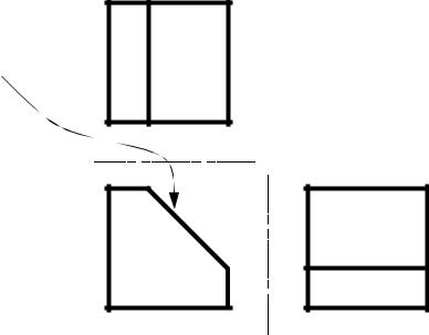
•an example is given below, and all faces are drawn for illustration, but normally only the angled face would be drawn. Because this is the first auxiliary from the drawing, it is called the primary auxiliary view.
Step 1: decide to draw the angled face of the block,
using the front view, because an edge view is available.

page 98
Step 2: draw construction lines perpendicular to the face, the view will be drawn in the open space in the upper right opening.
Step 3: draw the fold line in for reference. Just as a visual check, each of the construction lines should be perpendicular
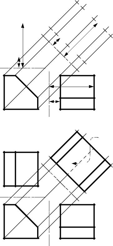
page 99
|
|
|
|
|
6 |
|
|
|
|
|
|
7 |
|
|
6,10 |
7 |
|
8 |
||
|
|
8,9 |
||||
Step 4: Transfer distances to find |
|
|
|
|
|
1 |
|
|
|
|
|
||
|
|
|
|
|
|
|
points in the auxiliary view. |
|
|
|
d2 |
|
2 |
Here the points are numbered |
|
|
|
|
d2 |
|
|
|
|
|
|
||
for the readers benefit. We can |
|
|
|
|
5 |
|
|
|
|
|
d1 |
||
transfer the distances either |
|
|
|
|
|
|
|
1,5 |
2 |
3,4 |
|
3 |
|
from the top or side view. |
|
|
||||
|
|
|
|
|
|
|
|
d1 |
|
4 |
|
|
|
|
1,6 |
2,7 |
2,1 |
7,6 |
|
|||
|
|
3 |
d2 |
|
|
8 |
|
|
3,8 |
|
|
|
|
|
|
|
d1 |
|
9,10 |
5,10 |
4,9 |
4,5 |
|
9
10
true surface
Step 5: the view is completed