

- •Table of Contents
- •Index
- •Keyword Reference
- •Installation
- •Installation of BASCOM
- •BASCOM IDE
- •Running BASCOM-AVR
- •File New
- •File Close
- •File Save
- •File Save As
- •File Print Preview
- •File Print
- •File Exit
- •View PinOut
- •View PDF viewer
- •View Error Panel
- •Edit Undo
- •Edit Redo
- •Edit Cut
- •Edit Copy
- •Edit Paste
- •Edit Find
- •Edit Find Next
- •Edit Replace
- •Edit Goto
- •Edit Toggle Bookmark
- •Edit Goto Bookmark
- •Edit Indent Block
- •Edit Unindent Block
- •Edit Remark Block
- •Program Compile
- •Program Syntax Check
- •Program Show Result
- •Program Simulate
- •Program Send to Chip
- •Tools Terminal Emulator
- •Tools LCD Designer
- •Tools LIB Manager
- •Tools Graphic Converter
- •Tools Stack Analyzer
- •Tools Plugin Manager
- •Tools Batch Compile
- •Options Compiler
- •Options Compiler Chip
- •Options Compiler Output
- •Options Compiler Communication
- •Options Compiler I2C, SPI, 1WIRE
- •Options Compiler LCD
- •Options Communication
- •Options Environment
- •Options Simulator
- •Options Programmer
- •Supported Programmers
- •ISP programmer
- •PG302 programmer
- •Sample Electronics cable programmer
- •KITSRUS Programmer
- •MCS Universal Interface Programmer
- •STK500 Programmer
- •Lawicel BootLoader
- •AVR ISP Programmer
- •USB-ISP Programmer
- •MCS Bootloader
- •Options Monitor
- •Options Printer
- •Window Cascade
- •Window Tile
- •Window Arrange Icons
- •Window Minimize All
- •Help About
- •Help Index
- •Help MCS Forum
- •Help MCS Shop
- •Help Support
- •Help Knowledge Base
- •Help Credits
- •BASCOM Editor Keys
- •Program Development Order
- •PlugIns
- •Font Editor
- •PinOut
- •BASCOM HARDWARE
- •Additional Hardware
- •AVR Internal Hardware
- •AVR Internal Registers
- •AVR Internal Hardware TIMER0
- •AVR Internal Hardware TIMER1
- •AVR Internal Hardware Watchdog timer
- •AVR Internal Hardware Port B
- •AVR Internal Hardware Port D
- •Adding XRAM
- •Attaching an LCD Display
- •Memory usage
- •Using the 1 WIRE protocol
- •Using the SPI protocol
- •Power Up
- •Chips
- •ATtiny22
- •ATtiny13
- •ATtiny15
- •ATtiny25
- •ATtiny45
- •ATtiny85
- •ATtiny26
- •ATtiny2313
- •ATMEGA8
- •ATMEGA16
- •ATMEGA32
- •ATMEGA48
- •ATMEGA88
- •ATMEGA168
- •ATMEGA64
- •ATMEGA103
- •ATMEGA128
- •ATMEGA161
- •ATMEGA162
- •ATMEGA163
- •ATMEGA165
- •ATMEGA169
- •ATMEGA323
- •ATMEGA603
- •ATMEGA8515
- •ATMEGA8535
- •BASCOM Language Fundamentals
- •Changes compared to BASCOM-8051
- •Language Fundamentals
- •Mixing ASM and BASIC
- •Assembler mnemonics
- •Reserved Words
- •Error Codes
- •Newbie problems
- •Tips and tricks
- •ASCII chart
- •BASCOM Language Reference
- •$BAUD
- •$BAUD1
- •$BOOT
- •$CRYSTAL
- •$DATA
- •$DEFAULT
- •$EEPLEAVE
- •$EEPROM
- •$EEPROMHEX
- •$EXTERNAL
- •$FRAMESIZE
- •$HWSTACK
- •$INCLUDE
- •$INITMICRO
- •$LCDPUTCTRL
- •$LCDPUTDATA
- •$LCDRS
- •$LCDVFO
- •$LOADER
- •$LOADERSIZE
- •$NOCOMP
- •$NOINIT
- •$NORAMCLEAR
- •$PROG
- •$PROGRAMMER
- •$REGFILE
- •$ROMSTART
- •$SERIALINPUT
- •$SERIALINPUT1
- •$SERIALINPUT2LCD
- •$SERIALOUTPUT
- •$SERIALOUTPUT1
- •$SWSTACK
- •$TIMEOUT
- •$TINY
- •$WAITSTATE
- •$XRAMSIZE
- •$XRAMSTART
- •1WIRECOUNT
- •1WRESET
- •1WREAD
- •1WSEARCHFIRST
- •1WSEARCHNEXT
- •1WVERIFY
- •1WWRITE
- •ACOS
- •ALIAS
- •ASIN
- •BASE64DEC
- •BASE64ENC
- •BAUD
- •BAUD1
- •BINVAL
- •BIN2GRAY
- •BITWAIT
- •BITS
- •BLOAD
- •BSAVE
- •BUFSPACE
- •BYVAL
- •CALL
- •CHECKSUM
- •CIRCLE
- •CLEAR
- •CLOCKDIVISION
- •CLOSE
- •CLOSESOCKET
- •CONFIG
- •CONFIG 1WIRE
- •CONFIG ACI
- •CONFIG ADC
- •CONFIG ATEMU
- •CONFIG BCCARD
- •CONFIG CLOCK
- •CONFIG CLOCKDIV
- •CONFIG COM1
- •CONFIG COM2
- •CONFIG COMx
- •CONFIG DATE
- •CONFIG DCF77
- •CONFIG DEBOUNCE
- •CONFIG I2CDELAY
- •CONFIG I2CSLAVE
- •CONFIG INPUT
- •CONFIG INTx
- •CONFIG GRAPHLCD
- •CONFIG KBD
- •CONFIG KEYBOARD
- •CONFIG LCD
- •CONFIG LCDBUS
- •CONFIG LCDMODE
- •CONFIG LCDPIN
- •CONFIG PORT
- •CONFIG PRINT
- •CONFIG PRINTBIN
- •CONFIG PS2EMU
- •CONFIG RC5
- •CONFIG SDA
- •CONFIG SCL
- •CONFIG SERIALIN
- •CONFIG SERIALIN1
- •CONFIG SERIALOUT
- •CONFIG SERIALOUT1
- •CONFIG SINGLE
- •CONFIG SPI
- •CONFIG SERVOS
- •CONFIG TCPIP
- •CONFIG TIMER0
- •CONFIG TIMER1
- •CONFIG TIMER2
- •CONFIG TWI
- •CONFIG TWISLAVE
- •CONFIG WAITSUART
- •CONFIG WATCHDOG
- •CONFIG X10
- •CONFIG XRAM
- •CONST
- •COSH
- •COUNTER0 and COUNTER1
- •CPEEK
- •CPEEKH
- •CRYSTAL
- •CURSOR
- •DATA
- •DAYOFWEEK
- •DAYOFYEAR
- •DATE$
- •DATE
- •DEBUG
- •DEBOUNCE
- •DECR
- •DECLARE FUNCTION
- •DECLARE SUB
- •DEFxxx
- •DEFLCDCHAR
- •DELAY
- •DISABLE
- •DISKFREE
- •DISKSIZE
- •DISPLAY
- •DO-LOOP
- •DriveCheck
- •DriveGetIdentity
- •DriveInit
- •DriveReset
- •DriveReadSector
- •DriveWriteSector
- •DTMFOUT
- •ECHO
- •ELSE
- •ENABLE
- •ENCODER
- •EXIT
- •FILEATTR
- •FILEDATE
- •FILEDATETIME
- •FILELEN
- •FILETIME
- •FLUSH
- •FORMAT
- •FOR-NEXT
- •FOURTHLINE
- •FRAC
- •FREEFILE
- •FUSING
- •GETADC
- •GETATKBD
- •GETATKBDRAW
- •GETDSTIP
- •GETDSTPORT
- •GETKBD
- •GETRC
- •GETRC5
- •GETTCPREGS
- •GETSOCKET
- •GLCDCMD
- •GLCDDATA
- •GOSUB
- •GOTO
- •GRAY2BIN
- •HEXVAL
- •HIGH
- •HIGHW
- •HOME
- •I2CINIT
- •I2CRECEIVE
- •I2CSEND
- •I2START,I2CSTOP, I2CRBYTE, I2CWBYTE
- •IDLE
- •IF-THEN-ELSE-END IF
- •INCR
- •INITFILESYSTEM
- •INITLCD
- •INKEY
- •INPUTBIN
- •INPUTHEX
- •INPUT
- •INSTR
- •ISCHARWAITING
- •KILL
- •LCASE
- •LCDAT
- •LCDCONTRAST
- •LEFT
- •LINE
- •LINE INPUT
- •LTRIM
- •LOAD
- •LOADADR
- •LOADLABEL
- •LOADWORDADR
- •LOCAL
- •LOCATE
- •LOOKDOWN
- •LOOKUP
- •LOOKUPSTR
- •LOWERLINE
- •MAKEBCD
- •MAKEINT
- •MAKEDEC
- •MAKETCP
- •MEMCOPY
- •NBITS
- •ON INTERRUPT
- •ON VALUE
- •OPEN
- •PEEK
- •POKE
- •POPALL
- •POWER
- •POWERDOWN
- •POWERSAVE
- •PRINTBIN
- •PSET
- •PS2MOUSEXY
- •PULSEIN
- •PULSEOUT
- •PUSHALL
- •RC5SEND
- •RC5SENDEXT
- •RC6SEND
- •READ
- •READEEPROM
- •READMAGCARD
- •RESET
- •RESTORE
- •RETURN
- •RIGHT
- •ROTATE
- •ROUND
- •RTRIM
- •SECELAPSED
- •SECOFDAY
- •SEEK
- •SELECT-CASE-END SELECT
- •SETFONT
- •SETTCP
- •SETTCPREGS
- •SENDSCAN
- •SENDSCANKBD
- •SERIN
- •SEROUT
- •SETIPPROTOCOL
- •SHIFT
- •SHIFTCURSOR
- •SHIFTIN
- •SHIFTOUT
- •SHIFTLCD
- •SHOWPIC
- •SHOWPICE
- •SINH
- •SOCKETCONNECT
- •SOCKETLISTEN
- •SOCKETSTAT
- •SONYSEND
- •SOUND
- •SPACE
- •SPIIN
- •SPIINIT
- •SPIMOVE
- •SPIOUT
- •SPLIT
- •START
- •STCHECK
- •STOP
- •STRING
- •SYSSEC
- •SYSSECELAPSED
- •SYSDAY
- •SWAP
- •TCPCHECKSUM
- •TCPREAD
- •TCPWRITE
- •TCPWRITESTR
- •TANH
- •THIRDLINE
- •TIME$
- •TIME
- •TOGGLE
- •TRIM
- •UCASE
- •UDPREAD
- •UDPWRITE
- •UDPWRITESTR
- •UPPERLINE
- •VARPTR
- •VERSION
- •WAIT
- •WAITKEY
- •WAITMS
- •WAITUS
- •WHILE-WEND
- •WRITE
- •WRITEEEPROM
- •X10DETECT
- •X10SEND
- •#IF ELSE ENDIF
- •International Resellers
- •International Resellers
- •ASM Libraries
- •EXTENDED I2C
- •MCSBYTE
- •MCSBYTEINT
- •TCPIP
- •LCD4BUSY
- •GLCD
- •GLCDSED
- •LCD-EPSON
- •AVR-DOS File System
- •CF Card
- •Compact FlashCard Driver
- •Elektor CF-Interface
- •XRAM CF-Interface for simulation
- •New CF-Card Drivers
- •Floating Point
- •FP_TRIG
- •DOUBLE
- •I2C SLAVE
- •I2CSLAVE
- •I2C TWI Slave
- •SPISLAVE
- •DATE TIME
- •EUROTIMEDATE
- •DATETIME
- •PS2-AT Mouse and Keyboard Emulation
- •AT_EMULATOR
- •PS2MOUSE_EMULATOR
- •BCCARD
- •BCCARD
- •BCDEF
- •BCCALL
- •BCRESET
- •Tools
- •LCD RGB-8 Converter

© MCS Electronics, 1995-2007
All trig functions work with radians. Use deg2rad and rad2deg to convert between radians and angles.
See Also
DEG2RAD
Example
'----------------------------------------------------------------------------- |
|
-- |
: (c) 1995-2005, MCS Electronics |
'copyright |
|
'micro |
: Mega48 |
'suited for demo |
: yes |
'commercial addon needed |
: no |
'purpose |
: demonstrates DEG2RAD function |
'----------------------------------------------------------------------------- |
|
-- |
|
Dim S As Single |
|
S = 90 |
|
S = Deg2Rad(s) |
|
Print S |
|
S = Rad2deg(s) |
|
Print S |
|
End |
|
RC5SEND
Action
Sends RC5 remote code.
Syntax
RC5SEND togglebit, address, command
Uses
TIMER1
Remarks
Togglebit |
Make the toggle bit 0 or 32 to set the toggle bit |
Address |
The RC5 address |
Command |
The RC5 command. |
|
|
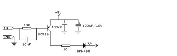
The resistor must be connected to the OC1A pin. In the example a 2313 micro was used. This micro has pin portB.3 connected to OC1A.
Look in a datasheet for the proper pin when used with a different chip.
Most audio and video systems are equipped with an infra-red remote control. The RC5 code is a 14-bit word bi-phase coded signal.
The two first bits are start bits, always having the value 1.
page -600-
© MCS Electronics, 1995-2007
The next bit is a control bit or toggle bit, which is inverted every time a button is pressed on the remote control transmitter.
Five system bits hold the system address so that only the right system responds to the code.
Usually, TV sets have the system address 0, VCRs the address 5 and so on. The command sequence is six bits long, allowing up to 64 different commands per address.
The bits are transmitted in bi-phase code (also known as Manchester code). An IR booster circuit is shown below:
See also
CONFIG RC5 , GETRC5 , RC6SEND
Example
'----------------------------------------------------------------------------- |
|
------------ |
: sendrc5.bas |
'name |
|
'copyright |
: (c) 1995-2005, MCS Electronics |
'purpose |
: code based on application note from Ger Langezaal |
'micro |
: AT90S2313 |
'suited for demo |
: yes |
'commercial addon needed |
: no |
'----------------------------------------------------------------------------- |
|
------------ |
|
$regfile = "2313def.dat" |
' specify the used |
micro |
' used crystal |
$crystal = 4000000 |
|
frequency |
' use baud rate |
$baud = 19200 |
|
$hwstack = 32 |
' default use 32 |
for the hardware stack |
' default use 10 |
$swstack = 10 |
|
for the SW stack |
' default use 40 |
$framesize = 40 |
|
for the frame space |
|
' +5V <---[A Led K]---[220 Ohm]---> Pb.3 for 2313.
'RC5SEND is using TIMER1, no interrupts are used
'The resistor must be connected to the OC1(A) pin , in this case PB.3
Dim Togbit As Byte , Command As Byte , Address As Byte
Command = |
12 |
' power on off |
32 |
Togbit = 0 |
' make it 0 or |
||
to set the toggle bit |
|
|
|
Address = |
0 |
|
|
page -601-

© MCS Electronics, 1995-2007
Do
Waitms 500
Rc5send Togbit , Address , Command
'or use the extended RC5 send code. You can not use both 'make sure that the MS bit is set to 1, so you need to send '&B10000000 this is the minimal requirement
'&B11000000 this is the normal RC5 mode '&B10100000 here the toggle bit is set
' Rc5sendext &B11000000 , Address , Command
Loop
End
RC5SENDEXT
Action
Sends extended RC5 remote code.
Syntax
RC5SENDEXT togglebit, address, command
Uses
TIMER1
Remarks
Togglebit |
Make the toggle bit 0 or 32 to set the toggle bit |
Address |
The RC5 address |
Command |
The RC5 command. |
|
|
Normal RC5 code uses 2 leading bits with the value '1'. After that the toggle bit follows. With extended RC5, the second bit is used to select the bank. When you make it 1 (the default and normal RC5) the RC5 code is compatible. When you make it 0, you select bank0 and thus use extended RC5 code.
The resistor must be connected to the OC1A pin. In the example a 2313 micro was used. This micro has pin portB.3 connected to OC1A.
Look in a datasheet for the proper pin when used with a different chip.
Most audio and video systems are equipped with an infra-red remote control. The RC5 code is a 14-bit word bi-phase coded signal.
The two first bits are start bits, always having the value 1.
The next bit is a control bit or toggle bit, which is inverted every time a button is pressed on the remote control transmitter.
Five system bits hold the system address so that only the right system responds to the code.
Usually, TV sets have the system address 0, VCRs the address 5 and so on. The command sequence is six bits long, allowing up to 64 different commands per address.
The bits are transmitted in bi-phase code (also known as Manchester code). An IR booster circuit is shown below:
page -602-
© MCS Electronics, 1995-2007
See also
CONFIG RC5 , GETRC5 , RC6SEND
Example
'----------------------------------------------------------------------------- |
|
------------ |
: sendrc5.bas |
'name |
|
'copyright |
: (c) 1995-2005, MCS Electronics |
'purpose |
: code based on application note from Ger Langezaal |
'micro |
: AT90S2313 |
'suited for demo |
: yes |
'commercial addon needed |
: no |
'----------------------------------------------------------------------------- |
|
------------ |
|
$regfile = "2313def.dat" |
' specify the used |
micro |
' used crystal |
$crystal = 4000000 |
|
frequency |
' use baud rate |
$baud = 19200 |
|
$hwstack = 32 |
' default use 32 |
for the hardware stack |
' default use 10 |
$swstack = 10 |
|
for the SW stack |
' default use 40 |
$framesize = 40 |
|
for the frame space |
|
' +5V <---[A Led K]---[220 Ohm]---> Pb.3 for 2313.
'RC5SEND is using TIMER1, no interrupts are used
'The resistor must be connected to the OC1(A) pin , in this case PB.3
Dim Togbit As Byte , Command As Byte , Address As Byte |
|
Command = 12 |
' power on off |
Togbit = 0 |
' make it 0 or 32 |
to set the toggle bit |
|
Address = 0 |
|
Do |
|
Waitms 500
' Rc5send Togbit , Address , Command
'or use the extended RC5 send code. You can not use both 'make sure that the MS bit is set to 1, so you need to send '&B10000000 this is the minimal requirement
'&B11000000 this is the normal RC5 mode '&B10100000 here the toggle bit is set Rc5sendExt &B11000000 , Address , Command
Loop
End
page -603-