- •Table of Contents
- •1. Introduction
- •2. CodeVisionAVR Integrated Development Environment
- •2.1 Working with Files
- •2.1.1 Creating a New File
- •2.1.2 Opening an Existing File
- •2.1.3 Files History
- •2.1.4 Editing a File
- •2.1.5 Saving a File
- •2.1.6 Renaming a File
- •2.1.7 Printing a File
- •2.1.8 Closing a File
- •2.1.9 Using the Navigator
- •2.1.10 Using Code Templates
- •2.1.11 Using Clipboard History
- •2.2 Working with Projects
- •2.2.1 Creating a New Project
- •2.2.2 Opening an Existing Project
- •2.2.3 Adding Notes or Comments to the Project
- •2.2.4 Configuring the Project
- •2.2.4.1 Adding or removing a File from the Project
- •2.2.4.2 Setting the C Compiler Options
- •2.2.4.3 Executing an User Specified Program before Make
- •2.2.4.4 Transferring the Compiled Program to the AVR Chip after Make
- •2.2.4.5 Executing an User Specified Program after Make
- •2.2.5 Obtaining an Executable Program
- •2.2.5.1 Checking the Project for Syntax Errors
- •2.2.5.2 Compiling the Project
- •2.2.5.3 Making the Project
- •2.2.6 Closing a Project
- •2.3 Tools
- •2.3.1 The AVR Studio Debugger
- •2.3.2 The AVR Chip Programmer
- •2.3.3 The Serial Communication Terminal
- •2.3.4 Executing User Programs
- •2.3.4.1 Configuring the Tools Menu
- •2.4 IDE Settings
- •2.4.1 The View Menu
- •2.4.2 Configuring the Editor
- •2.4.3 Configuring the Assembler
- •2.4.4 Setting the Debugger Path
- •2.4.5 AVR Chip Programmer Setup
- •2.4.6 Serial Communication Terminal Setup
- •2.5 Accessing the Help
- •2.6 Transferring the License to another computer
- •2.7 Connecting to HP InfoTech's Web Site
- •2.8 Contacting HP InfoTech by E-Mail
- •2.9 Quitting the CodeVisionAVR IDE
- •3. CodeVisionAVR C Compiler Reference
- •3.1 The Preprocessor
- •3.2 Comments
- •3.3 Reserved Keywords
- •3.4 Identifiers
- •3.5 Data Types
- •3.6 Constants
- •3.7 Variables
- •3.7.1 Specifying the SRAM Storage Address for Global Variables
- •3.7.2 Bit Variables
- •3.7.3 Allocation of Variables to Registers
- •3.7.4 Structures
- •3.7.5 Unions
- •3.7.6 Enumerations
- •3.7.7 Global Variables Memory Map File
- •3.8 Defining Data Types
- •3.9 Type Conversions
- •3.10 Operators
- •3.11 Functions
- •3.12 Pointers
- •3.13 Accessing the I/O Registers
- •3.13.1 Bit level access to the I/O Registers
- •3.14 Accessing the EEPROM
- •3.15 Using Interrupts
- •3.16 SRAM Memory Organization
- •3.17 Using an External Startup File
- •3.18 Including Assembly Language in Your Program
- •3.18.1 Calling Assembly Functions from C
- •3.19 Creating Libraries
- •3.20 Using the AVR Studio Debugger
- •3.20.1 Using the AVR Studio Debugger version 3
- •3.20.2 Using the AVR Studio Debugger version 4.06 or later
- •3.21 Hints
- •3.22 Limitations
- •4. Library Functions Reference
- •4.1 Character Type Functions
- •4.2 Standard C Input/Output Functions
- •4.3 Standard Library Functions
- •4.4 Mathematical Functions
- •4.5 String Functions
- •4.6 Variable Length Argument Lists Macros
- •4.7 Non-local Jump Functions
- •4.8 BCD Conversion Functions
- •4.9 Gray Code Conversion Functions
- •4.10 Memory Access Functions
- •4.11 LCD Functions
- •4.11.1 LCD Functions for displays with up to 2x40 characters
- •4.11.2 LCD Functions for displays with 4x40 characters
- •4.11.3 LCD Functions for displays connected in 8 bit memory mapped mode
- •4.12 I2C Bus Functions
- •4.12.3 Philips PCF8563 Real Time Clock Functions
- •4.12.4 Philips PCF8583 Real Time Clock Functions
- •4.14 1 Wire Protocol Functions
- •4.14.3 Maxim/Dallas Semiconductor DS2430 EEPROM Functions
- •4.14.4 Maxim/Dallas Semiconductor DS2433 EEPROM Functions
- •4.15 SPI Functions
- •4.16 Power Management Functions
- •4.17 Delay Functions
- •5. CodeWizardAVR Automatic Program Generator
- •5.1 Setting the AVR Chip Options
- •5.2 Setting the External SRAM
- •5.3 Setting the Input/Output Ports
- •5.4 Setting the External Interrupts
- •5.5 Setting the Timers/Counters
- •5.6 Setting the UART or USART
- •5.7 Setting the Analog Comparator
- •5.8 Setting the Analog-Digital Converter
- •5.9 Setting the ATmega406 Voltage Reference
- •5.10 Setting the ATmega406 Coulomb Counter
- •5.11 Setting the SPI Interface
- •5.12 Setting the Universal Serial Interface - USI
- •5.13 Setting the I2C Bus
- •5.13.1 Setting the LM75 devices
- •5.13.2 Setting the DS1621 devices
- •5.13.3 Setting the PCF8563 devices
- •5.13.4 Setting the PCF8583 devices
- •5.13.5 Setting the DS1307 devices
- •5.14 Setting the 1 Wire Bus
- •5.15 Setting the 2 Wire Bus
- •5.16 Setting the CAN Controller
- •5.17 Setting the ATmega169/329/3290/649/6490 LCD Controller
- •5.18 Setting the LCD
- •5.19 Setting the USB Controller
- •5.20 Setting Bit-Banged Peripherals
- •5.21 Specifying the Project Information
- •6. License Agreement
- •6.1 Software License
- •6.2 Liability Disclaimer
- •6.3 Restrictions
- •6.4 Operating License
- •6.5 Back-up and Transfer
- •6.6 Terms
- •6.7 Other Rights and Restrictions
- •7. Technical Support
- •8. Contact Information
CodeVisionAVR
5.8 Setting the Analog-Digital Converter
Some AVR chips contain an analog-digital converter (ADC).
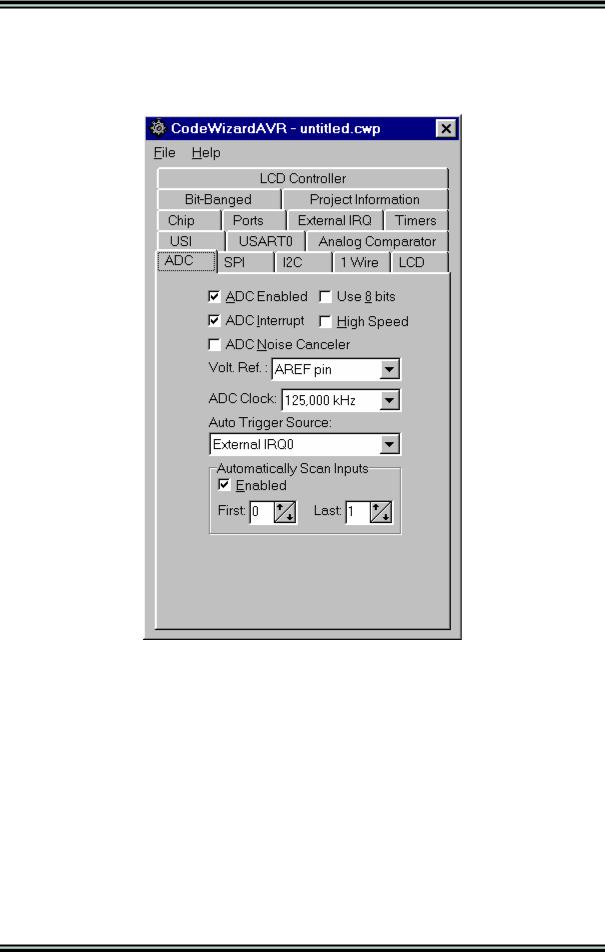
By selecting the ADC tab of the CodeWizardAVR, you can specify the ADC configuration.
Checking the ADC Enabled check box enables the on-chip ADC.
On some AVR devices only the 8 most significant bits of the AD conversion result can be used. This feature is enabled by checking the Use 8 bits check box.
Some AVR devices allow the ADC to use a high speed conversion mode, but with lower precision. This feature is enabled by checking the High Speed check box.
If the ADC has an internal reference voltage source, than it can be selected using the Volt. Ref. list box or activated by checking the ADC Bandgap check box.
© 1998-2007 HP InfoTech S.R.L. |
Page 196 |
CodeVisionAVR
Some AVR devices allow the AD conversion to be triggered by an event which can be selected using the Auto Trigger Source list box.
If you want to generate interrupts when the ADC finishes the conversion, then you must check the
ADC Interrupt check box.
If ADC interrupts are used you have the possibility to enable the following functions:
•by checking the ADC Noise Canceler check box, the chip is placed in idle mode during the conversion process, thus reducing the noise induced on the ADC by the chip's digital circuitry
•by checking the Automatically Scan Inputs Enabled check box, the CodeWizardAVR will generate code to scan an ADC input domain and put the results in an array. The start, respectively the end, of the domain are specified using the First Input, respectively the Last Input, spinedit boxes.
If the automatic inputs scanning is disabled, then a single analog-digital conversion can be executed using the function:
unsigned int read_adc(unsigned char adc_input)
This function will return the analog-digital conversion result for the input adc_input. The input numbering starts from 0.
If interrupts are enabled the above function will use an additional interrupt service routine adc_isr. This routine will store the conversion result in the adc_data global variable.
If the automatic inputs scanning is enabled, the adc_isr service routine will store the conversion results in the adc_data global array. The user program must read the conversion results from this array.
© 1998-2007 HP InfoTech S.R.L. |
Page 197 |
CodeVisionAVR
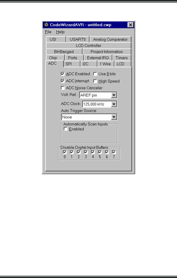
For some chips, like the Atmega169V/L, there is also the possibility to disable the digital input buffers on the inputs used by the ADC, thus reducing the power consumption of the chip.
This is accomplished by checking the corresponding Disable Digital Input Buffers check boxes.
If the Automatically Scan Inputs option is enabled, then the corresponding digital input buffers are automatically disabled for the ADC inputs in the scan range.
© 1998-2007 HP InfoTech S.R.L. |
Page 198 |
CodeVisionAVR
5.9 Setting the ATmega406 Voltage Reference
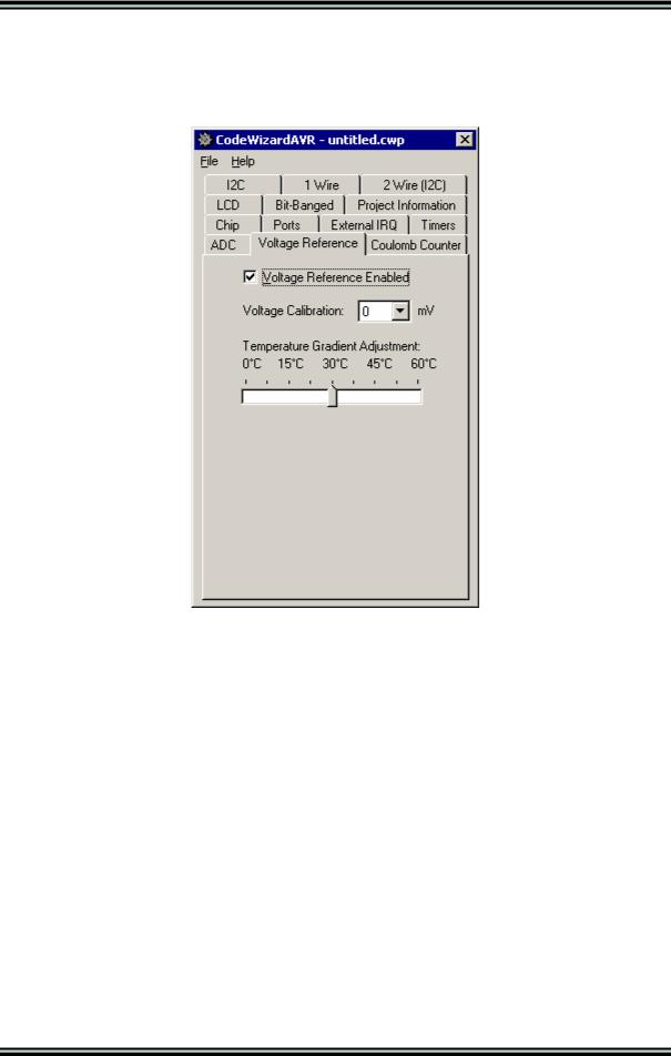
Some AVR chips, like the Atmega406, contain a low power precision bang-gap voltage reference, which can be configured by selecting the Voltage Reference tab of the CodeWizardAVR.
Checking the Voltage Reference Enabled check box enables the precision voltage reference.
The Voltage Calibration list box allows for precision adjustment of the nominal value of the reference voltage in 2mV steps.
The Temperature Gradient Adjustment slider allows shifting the top of the VREF versus temperature curve to the center of the temperature range of interest, thus minimizing the voltage drift in this range. The Atmega406 datasheet may be consulted for more details.
© 1998-2007 HP InfoTech S.R.L. |
Page 199 |