

2 - Ophir - тоже камеры
.pdfINSIDE LOOK AT BEAM PROFILING TECHNOLOGY
Tech Tips:
Solar Cells, Welding, M2,
and More
Lasers at Work in Scientific,
Medical Research, Aerospace &
Manufacturing
New Products:
Cameras, Scanning Slit,
Profilers & M2
Reference Charts:
Profiling Algorithms,
Physical Constant &
Conversions


 WELCOME
Issue 1:2013
In This Issue: |
|
Intro to Laser Beam Profiling........................... |
3 |
Technology |
|
Beam Profiling: The Technology...................... |
5 |
What is M2?....................................................... |
9 |
What Beam Shape Did You Get?.................... |
11 |
Old Acrylic Blocks are a Thing of the Past.... |
13 |
Reference Algorithms.................................... |
29 |
Applications |
|
Laser Welding in Medical Devices................. |
15 |
Lasers & Solar Cell Manufacturing................ |
17 |
Space-Based Atmospheric Measurements... |
19 |
Lensed & Tapered Specialty Fibers............... |
21 |
Products |
|
Spatial Measurements |
|
BeamGage.................................................... |
23 |
NanoScan..................................................... |
24 |
Accessories.................................................... |
25 |
Beam Propagation Measurements |
|
M2-200s......................................................... |
26 |
ModeScan 1780............................................ |
27 |
NanoModeScan............................................ |
28 |
EDITOR
Shari Worthington
Telesian Technology
www.telesian.com
CONTRIBUTORS
Allen Cary, Kenneth Ferree, Dr. Etienne Friedrich, Dr. Jeffrey Guttman, Todd Jacobson, Kevin Kirkham, Dick Rieley, Gary Wagner
www.ophiropt.com/photoncics
GRAPHIC DESIGN & LAYOUT
Bob Olsen
Olsen Ad/Com
www.olsenad.com
© 2013, Ophir-Spiricon, LLC. A Newport Corporation brand. All rights reserved. Requests to reprint should be sent to sales@us.ophiropt.com.
We are pleased to bring you this special technology update devoted to the expanding field of laser beam profiling and analysis. You will find it packed with information on new approaches to your measurement and automation needs. Our goal is to bring you the most up-to-date information on laser beam profiling and provide you with a complete picture of the business issues, technology, applications, and products involved in beam profiling. We start with an overview of the beam profiling industryanddiscusstheissuesdrivingthemeasurement and monitoring of laser beam quality. We then turn to a series of features on the core techniques used in measuring the various beam parameters. We’ve also interspersed a series of “technical tips” to help you
head off potential problems.
The next section describes a range of case histories, companies small and large who have implemented beam parameter measurement. They discuss how this process affects the outcome of their operations, including such rewards as more consistent production, optimum machine performance, lower manufacturing costs, and increased sales to quality-conscious customers. Finally, we showcase some of the leading beam profiling systems available on the market.
Ophir-Spiricon, and its predecessors have long been innovative pioneers in the beam profiling industry. John Fleischer, founder of Photon, chaired the working laser beam width ISO/DIN committee that resulted in the ISO/DIN 11146 standard. While Dr. Carlos Roundy, Spiricon’s founder, invented Ultracal™, the baseline correction algorithm used in the ISO 11146-3 standard. This standard governs profile measurements and analysis using scanning apertures, variable apertures, area sensors, and detector arrays. Profiles obtained using these methods differ fundamentally, and each requires specific analyses to determine beam characterization parameters, most important of which is the beam width or diameter.
With over 30 years of experience, Ophir, Spiricon, and Photon, all Newport Corporation brands, provide a complete line of instrumentation, including power and energy meters, beam profilers, spectrum analyzers, and goniometric radiometers. The company’s modular, customizable solutions serve manufacturing, medical, military, and research industries throughout the world.
We are here to help you get the most out of your laser-based application. Most people don’t realize they need to do beam profiling until they see the profile of their own laser. The measurements are generally not what they think they are. We look forward to discussing your application and are ready to show you profiling on your beam.
Gary Wagner
GENERAL MANAGER, OPHIR PHOTONICS (U.S.)
Ophir-Spiricon, LLC |
Ophir Optronics Solutions Ltd |
Ophir Japan Ltd. |
Spiricon GmbH |
||
Spiricon & Photon Manufacturing, |
Ophir Distribution Center |
Ophir Distribution and Calibration |
Ophir Distribution and Calibration |
||
Ophir Distribution and Calibration |
POB 45021 |
Center |
Center |
||
Center |
|
Science-Based Industrial Park |
4-384 Sakuragi, |
An der Strusbek 60-62 |
|
3050 North 300 West |
Har Hotzvim 91450 |
Omiya, Saitama-city, |
D-22926 Ahrensburg |
||
North Logan, UT 84341 USA |
Jerusalem, Israel |
Saitama 330-0854, Japan |
Germany |
||
Phone: +435-753-3729 |
Phone: +972-2-548-7414 |
Phone: +81-48-646 4150 |
Phone: +49-4102 6671802 |
||
www.ophiropt.com/photonics |
www.ophiropt.com/photonics |
www.ophiropt.com/jp |
www.spiricon.de |
||
|
|
|
|||
Page 2 |
|
O P H I R P H O T O N I C S , W W W . O P H I R O P T . C O M / P H O T O N I C S |
|
||
|
|
|
|
|
|
WHY BEAM PROFILING?
BENEFITS OF MEASURING SPATIAL CHARACTERISTICS OF LASER BEAMS
By Allen Cary, Director of Marketing, Ophir Photonics
Generally, people working with lasers are trying to do something with the light beam, either as the raw beam or, more commonly, modified with optics. Whether it is printing a label on a part, welding a precision joint, or repairing a retina, it is
important to understand the nature of the laser beam and its performance.
Laser beam profiling provides the tools to characterize the laser, and know precisely what the beam is doing at the point of the work and if the optics are having the desired effect.
Lasers and laser applications come in many varieties, varying in power density, wavelength, depth-of-focus, beam size, pulse duration, and myriad other parameters. It is this variety that makes lasers so useful for interacting with and manipulating different materials and media across industries and applications.
SIX BENEFITS OF LASER BEAM PROFILING:
λDesign and specify correct components for use in your optical system
Select the right lenses to create the proper beam size for the job in the proper location
λReduce conflicts in the evaluation of laser beam performance
Have reproducible numerical values to indicate acceptable criteria for beam performance that everyone can agree upon
continued on page 4
B E A M P R O F I L I N G Page 3
WHY |
λ |
Realize savings in time, effort, and cost |
BEAM PROFILING? |
|
in assembling optical systems |
continued from page 3 |
|
Be able to reject defective or inappropriate |
|
|
|
|
|
sources or components before spending |
|
|
additional value-added activities on |
|
|
optical assemblies |
|
λ |
Save time adjusting optimum optical |
|
|
system performance |
|
|
Make adjustments to systems with real |
|
|
time feedback to obtain the proper per- |
|
|
formance for the intended job of the laser |
|
|
system |
|
λ Avoid wasting power output capabilities |
|
|
|
Optimize power coupling of sources to |
|
|
optical components or systems to avoid |
|
|
unnecessary losses. |
|
λ Protect against damage due to |
|
|
|
inappropriate beam distribution |
|
|
(e.g., hot spots) |
|
|
Ensure that power distribution of the |
|
|
laser beam is uniform and conforms to |
|
|
the design intended, avoiding hot spots |
|
|
that can distort welds, cut materials, and |
|
|
otherwise produce defective end products |
|
|
|
Download the latest
Laser Measurement
Applications catalogs.
Each issue covers a wide range of state-of-the-art beam profiling and power/energy sensor technologies for medical, industrial, defense, and research applications.
-Laser Beam Profiling Catalog
-Power/Energy Meters and Beam
Profilers Catalog
www.ophiropt.com/laser- measurement-instruments/ beam-profilers/services/catalog- download
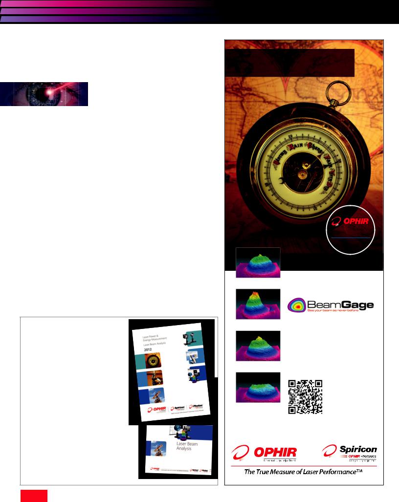
The barometer was invented in Italy in 1643
to measure atmospheric pressure and has been serving mankind ever since.
Now Part of the
Newport Corporation
Family of world-class photonics brands
Designed toMeasusurere
No one needs a laser beam profiler until they see what their beam really looks like.
Here are four beams from the same laser model. It’s well known that:
•Beams change over time.
•Focus spot shifts over power changes
•Intensity distribution changes with aging optics
See for yourself, on your laser, at your site. Call for a demo.
1-866-755-5499 www.ophiropt.com/photonics
Page 4 O P H I R P H O T O N I C S , W W W . O P H I R O P T . C O M / P H O T O N I C S
CHOOSING A BEAM PROFILER
By Kevin Kirkham, Beam Profiling Specialist, Ophir-Spiricon
Alaser beam profiler will increase your chance of success anytime you wish to design or apply a laser or when you find your laser system is no longer meeting specifications.
You would never think of trying to build a mechanical part without a micrometer. So why attempt to build lasers or laser systems with only a power meter? You will produce the desired results more quickly if you can measure basic things like beam width or size, beam profile and power.
We believe as Lord Kelvin said: “You cannot improve it if you cannot measure it”.
FOUR BASIC QUESTIONS
When choosing a laser beam profiler there are a plethora of choices to do the job, including CCD and CMOS cameras, scanning slit sensors, InGaAs and pyroelectric cameras, pinhole, and knife edge sensors to mention some. How does one decide which is the proper solution for one’s application and from which company to obtain the profiler system? When making the selection there are four basic questions about the laser application that one must answer.
WAVELENGTH?
The first question is: What wavelength(s) do you intend to measure? The answer to this question determines the type of detector needed, and what the most cost effective approach may be. For the UV and visible wavelength range from <193nm up to the very near infrared at around 1300nm, silicon detectors have the response to make these measurements. The largest number of cost effective solutions exist for these wavelengths including CCD cameras and silicon de- tector-equipped scanning aperture systems. Which of these is the best will be determined by the answers to the other three questions.
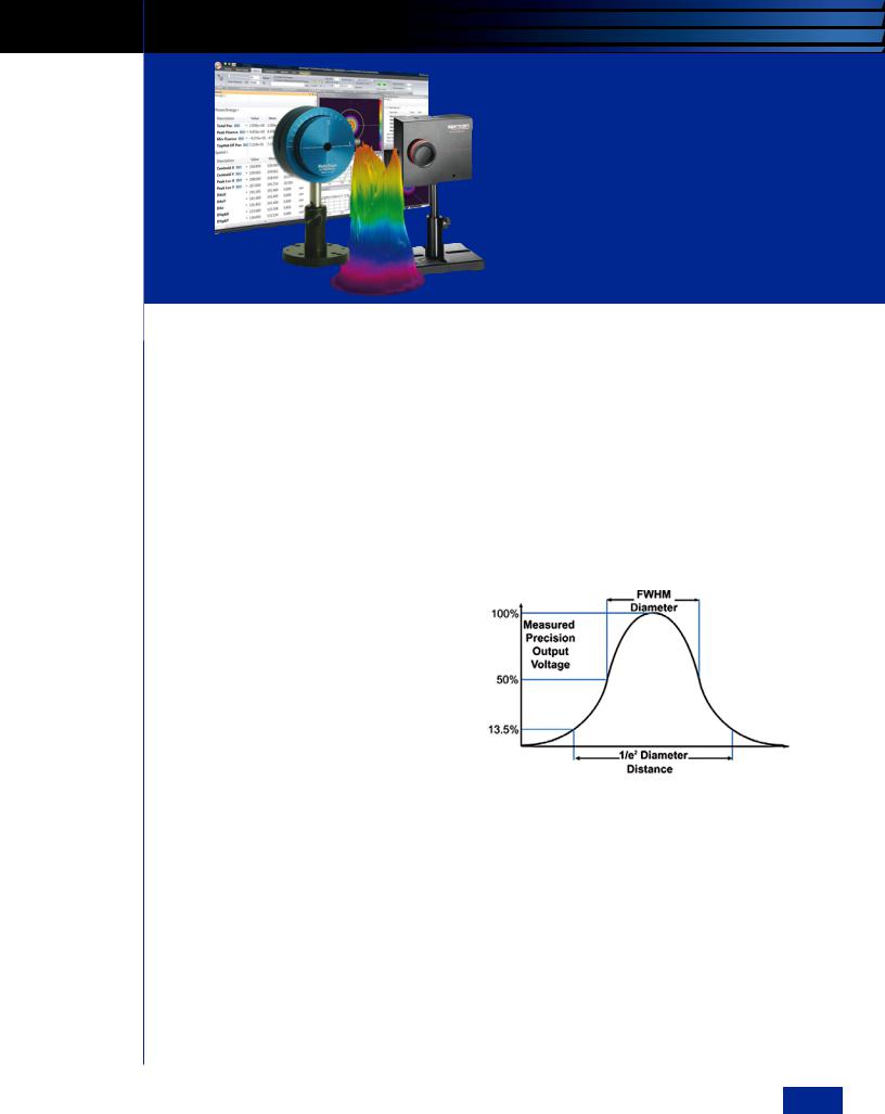
Figure 1
For the near infrared, from 800 to 1700nm, the choices become less abundant. In the lower end of this range from 800–1300nm the CCD cameras may still work, but InGaAs arrays become necessary above 1300nm. These are quite expensive; four to five times the cost of the silicon CCDs. Scanning slit systems equipped with germanium detectors are still quite reasonably priced, within a few hundred dollars of their silicon-equipped cousins. At the mid and far infrared wavelengths the pyroelectric cameras and scanning slits sensors with pyroelectric detectors provide viable alternatives, again the best approach being determined by
the answers to the subsequent questions.
continued on page 6
B E A M P R O F I L I N G Page 5
CHOOSING A BEAM PROFILER
continued from page 5
BEAM SIZE?
The second question is: What beam width or spot size do you wish to measure? This question can also impact the profiler type choices. Arrays are limited by the size of their pixels . At the current state-of- the-art pixels are at best around 4µm for silicon arrays, and considerably larger, 30um to 80um with InGaAs and pyroelectric cameras. This means that a UV-NIR beam should be larger than 50µm or roughly 10 pixels in diameter to ensure that enough pixels are utilized to make an accurate measurement. Beams with spot sizes smaller than 50um can be optically magnified or expanded to be measured with a camera. InGaAs camera pixels are around 30µm, limiting the minimum measurable beam size to 300µm; pyroelectric array pixels are even larger at 80µm, meaning the beams need to be at least 0.8mm to yield accurate results. Scanning slit profilers can measure with better than 2% accuracy beams that are four times the slit width or larger, putting the minimum beam sizes at around 8µm without magnification. Those investigators who want to measure their beams directly
without additional optics could find this to be an advantage.
POWER?
The third question is: What is the power of the beam? This determines the need for attenuation, and/or beam splitting, as well as the detector type. Array detectors, such as silicon CCD, CMOS, InGaAs and Pyroelectric cameras will usually need attenuation when measuring lasers. Scanning slit
type profilers can measure many beams directly without any attenuation, due to the natural attenuation of the slit itself. Detector arrays and knife-edge profilers, by their nature, will allow the entire beam to impact the detector at some point in the measurement, leading to detector saturation unless the beam is appropriately attenuated. Lasers of any wavelength with CW powers above 100mW can be measured with the pyroelectric detectorequipped scanning slit profiler, making it the easiest profiler for many applications. Scanning
slit profilers can directly measure up to kilowatts of laser power, depending on the spot size or power density.
CW OR PULSED?
The final question is: Is the laser continuous wave (CW) or pulsed? Lasers that operate pulsed at repetition rates less than ~10 kHz are best profiled with an array. Scanning apertures simply cannot make these measurements effectively in “real time”. CW and pulsed beams with repetition rates above ~10 kHz can be measured with scanning slits if the combination of the repetition rate and the beam size are sufficient to have enough laser pulses during the transit time of the slits through the beam to obtain a good profile. Knife-edge profilers are only able to measure CW beams. Pulsed beams have other considerations when selecting a beam profiling instrument, particularly pulse-to-pulse repeatability, and pulse-energy damage thresholds of the slit material or in the case of array detectors, beam sampling optics.
ONE MORE QUESTION
|
Besides these four questions about |
||
|
the |
physical nature of |
the laser to |
|
be measured, there is one more that |
||
|
needs to be asked: How accurate does the |
||
|
measurement need to be? Not all profilers |
||
|
or profiler companies are equal in this |
||
|
regard. Properly designed, maintained |
||
|
and |
calibrated camera |
based and |
|
slit profilers can provide submicron |
||
|
precision for both beam width and beam |
||
Figure 2 |
position (centroid) measurements. |
||
A state-of-the-art CCD array with 4µm pixels can provide ±2% beam width accuracy for beams larger than 50µm. Accuracy for smaller beams may be worse due to the effects of insufficient resolution or pixilation. In addition, the effects of attenuation optics, noise and proper baseline zeroing or offset compensation can have dramatic impact on the accuracy of the measurement. Cameras that are not designed specifically for profiling may be much worse due to the presence of a cover glass and/or IR cut-off filter covering the array. These optical
Page 6 O P H I R P H O T O N I C S , W W W . O P H I R O P T . C O M / P H O T O N I C S
User Guide for Choosing the Optimum Beam Profiling System
Table 1
Laser |
|
|
Power |
|
|
Minimum |
|
|
|
|
|
|
Wavelength |
|
|
|
Beam Size |
|
|
|
|
|
|
||
|
|
|
<100mW |
100mW-100W |
>100W |
<10µm |
<20µm |
>20 |
>50µm |
>500µm |
>1mm |
|
|
|
|
<50µm |
|
||||||||
|
|
|
|
|
|
|
|
|
|
|
|
|
|
|
|
|
|
|
|
|
|
|
|
|
|
|
|
|
NS-Si |
NS-Pyro |
HP-NS |
NS-Si/3.5/1.0 |
NS-Si/3.5/1.8 NS-Si/9/5 |
NS-Si/9/5 |
NS-Si /9/5 |
NS-Si /9/5 |
|
|
UV-Vis |
|
|
SP620 |
SP620 |
NS-Pyro |
|
|
NS-Pyro/9/5 |
NS-Pyro/9/5 |
NS-Pyro/9/5 |
NS-Pyro/9/5 |
|
|
|
|
|
|
|
|
|
|
|
|
|
|
|
|
|
|
|
SP620 |
|
|
|
SP620 |
SP620 |
SP620 |
|
|
|
|
SP620 |
NS-Pyro |
HP-NS |
NS-Ge/3.5/1.0 |
NS-Ge/3.5/1.8 NS-Ge/9/5 |
NS-Ge/9/5 |
NS-Ge/9/5 |
NS-Ge/9/5 |
|
|
|
|
|
|
|
|
|
|
|
|
|
|
|
NIR 1000- |
|
|
NS-Ge |
SP620 |
NS-Pyro |
|
|
NS-Pyro/9/5 |
NS-Pyro/9/5 |
NS-Pyro/9/5 |
NS-Pyro/9/5 |
|
|
|
|
|
|
|
|
|
|
|
|
|
|
1100nm |
|
|
|
|
SP620 |
|
|
|
SP620 |
SP620/ SP503 |
|
|
|
|
|
|
|
|
|
|
|
|
|
|
|
|
|
|
|
|
|
|
|
|
|
Pyrocam |
|
|
|
|
|
NS-Ge |
NS-Pyro |
HP-NS |
NS-Ge/3.5/1.0 |
NS-Ge/3.5/1.8 NS-Ge/9/5 |
NS-Ge/9/5 |
NS-Ge/9/5 |
NS-Ge/9/5 |
|
|
Telecom and |
|
|
NS-Pyro |
|
|
NS-Pyro/9/5 |
NS-Pyro/9/5 |
NS-Pyro/9/5 |
NS-Pyro/9/5 |
|
||
|
|
|
|
|
|
|
|
|
|
|||
Eye-Safe 1100- |
|
|
|
|
|
|
XEVA |
XEVA |
XEVA |
|
||
1800nm |
|
|
|
|
|
|
|
|
|
|||
|
|
|
|
|
|
|
|
|
|
|
|
|
|
|
|
|
|
|
|
|
|
|
Pyrocam |
Pyrocam |
|
|
|
|
|
|
|
|
|
|
|
|
|
|
|
|
|
NS-Ge |
NS-Ge |
NS-Ge |
NS-Ge/3.5/1.0 |
NS-Ge/3.5/1.8 NS-Ge/9/5 |
NS-Ge/9/5 |
Pyrocam |
NS-Ge/9/5 |
|
|
1500-1600nm |
|
|
|
|
|
|
|
|
|
|
|
|
|
SP 620-1550 |
SP 620-1550 |
SP 620-1550 |
|
|
|
SP 620-1550 |
XEVA |
SP 620-1550 |
|
||
|
|
|
|
|
|
|
||||||
|
|
|
Pyrocam |
NS-Pyro |
HP-NS |
Pyrocam |
Pyrocam |
NS-Pyro/9/5 |
NS-Pyro/9/5 |
NS-Pyro/9/5 |
NS-Pyro/9/5 |
|
|
|
|
|
|
|
w/ Beam |
w/ Beam |
|
|
|
|
|
|
|
|
|
|
|
Expansion |
Expansion |
|
|
|
|
|
MIR & FIR |
|
|
|
Pyrocam |
NS-Pyro |
|
|
|
|
Pyrocam |
Pyrocam |
|
|
|
|
|
|
Pyrocam |
|
|
|
|
|
|
|
|
|
|
|
|
ModeCheck |
|
|
|
|
|
|
|
|
|
|
|
|
|
|
|
|
|
|
|
|
Abbreviations: |
|
|
|
|
|
|
|
|
|
|
||
FIR |
Far Infrared |
NIR |
Near Infrared |
|
|
|
|
|
|
|
||
Ge |
Germanium |
Si |
Silicon |
|
|
|
|
|
|
|
||
HP |
High Power |
SP |
Indicates camera profiler |
|
|
|
|
|
|
|||
MIR |
Mid-Infrared |
NS |
NanoScan |
|
|
|
|
|
|
|
||
UV-Vis |
Ultraviolet - Visible |
|
|
|
|
|
|
|
|
|
||
elements must be removed for laser profiling to prevent interference fringes or distortion of the beam being tested. Camera arrays provide a true two-dimensional picture of the beam and will show fine structure and hot and cold spots, which a slit will integrate out. Some applications do not require a map
of the laser power distribution with in the spot. Spot size and spot location are sufficient. Other applications require that a careful mapping of the complete mode structure is made. These applications require 2D, array based sensors. The accuracy requirement is a question of what the data is to be used for. Accurate collimation or focus control requires the highest beam size accuracy. Checking the
Figure 3
laser for hot spots, uniformity or beam shape dictates that the 2D sensor is employed and is as important as absolute size measurement accuracy.
How and where a profiler is to be used is also an important consideration in the equation. Profilers used by research and development scientists are often specialized. Ease-of-use and high throughput may be of no consequence if the purpose is to characterize specific optical systems that are well understood by the investigator. On the other hand, when a profiler needs to be used on the factory floor for quality assurance of the manufacturing process, ease-of-use, high throughput, and reproducibility become paramount. In this case the profiler requiring continued on page 8
B E A M P R O F I L I N G Page 7
CHOOSING A BEAM PROFILER
continued from page 7
Page 8 O P H I R
the least “fiddling” is generally the best fit. Here there is a competition between the intuitive and the ease-of-use. Some people find the 2-dimensional camera array to be the most intuitive, because they can relate to the idea of “taking a picture” of the laser beam; X-Y scanning slits may seem less intuitive. For any process that uses or works with CW or high frequency pulsed lasers the scanning slit will have the advantage of measuring the beam directly, possibly even at its focus point, without additional attenuation optics. The dynamic range of these systems may also be broad enough to measure both the focused and the unfocused beam without changing the level of attenuation. Camera arrays, on the other hand will require attenuation adjustment.
Conversely, if the important aspect of the measurement is the two-dimensional image of the beam, or if the laser is pulsed at a low repetition rate, the array will be the solution; even if it means attenuation optics.
Also, many factory applications may want to ‘em-
bed’ the beam profiler into a manufacturing cell or a piece of automation so the measurements and possibly pass/fail results are completed automatic. If so look for a system that has this ability. Most often the capability to interface the profiler into the overall system through a LabView, Excel or .NET interface is available.
So Camera or scanning slit, whichever is selected the user must first determine the laser beam measurement environment and what information about the beam profile is most important to the success of the application. Ease of use and absolute spot size favors the scanning slit system while knowing about the hot and cold spots or the image of the beam under test, or any low repetition pulsed laser, requires a camera based beam profiling system. The assistance of knowledgeable product specialists is required to provide analysis of the measurement requirements of your laser application as well as to describe the features and benefits of available products.
Table 2
Laser |
|
Minimum |
|
CW or Pulsed |
|
Customer Priority |
|
|
|
||
Wavelength |
|
Beam Size |
|
|
|
|
|
|
|
|
|
|
|
>5mm |
>10mm |
CW |
Pulsed |
Pulsed |
Price |
2D/3D |
No optics |
Speed |
Ease of use |
|
|
<1kHz |
>1kHz |
||||||||
|
|
|
|
|
|
|
|
|
|
||
|
|
|
|
|
|
|
|
|
|
|
|
|
|
NS-Si /9/5 |
NS-Si /25/25 NS |
SP620 |
SP620 |
SP620 |
SP620 |
NS |
NS |
NS |
|
UV-Vis |
|
NS-Pyro/20/25 |
NS-Pyro/20/25 |
SP620 |
|
NS |
|
|
|
|
|
|
|
|
|
|
|
|
|
|
|
|
|
|
|
SP620 |
L11058 |
|
|
|
|
|
|
|
|
|
|
NS-Ge/12/25 |
|
NS |
SP620 |
SP620 |
SP620 |
SP620 |
NS |
NS |
NS |
|
|
|
|
|
|
|
|
|
|
|
|
NIR 1000- |
|
NS-Pyro/20/25 |
NS-Pyro/20/25 |
SP620 |
|
NS |
|
|
|
|
|
|
|
|
|
|
|
|
|
|
|
|
|
1100nm |
|
|
|
|
|
|
|
|
|
|
|
|
|
|
|
|
|
|
|
|
|
|
|
|
|
NS-Ge/12/25 |
|
NS |
XEVA |
XEVA |
NS |
XEVA |
NS |
NS |
NS |
Telecom |
|
NS-Pyro/20/25 |
NS-Pyro/20/25 |
|
|
NS |
|
Pyrocam |
|
|
|
and Eye- |
|
|
|
|
|
|
|
||||
|
|
|
|
|
|
|
|
|
|
|
|
Safe 1100Pyrocam |
|
|
|
|
|
|
|
|
|
||
1800nm |
|
|
|
|
|
|
|
|
|
|
|
|
|
|
|
|
|
|
|
|
|
|
|
1500- |
|
NS-Ge/12/25 |
NS-Pyro/20/25 |
|
|
NS |
|
|
|
|
|
|
|
|
|
|
|
|
|
|
|
|
|
1600nm |
|
SP 620-1550 |
|
XEVA |
XEVA |
XEVA |
SP 620-1550 SP 620-1550 |
NS |
NS |
NS |
|
|
|
NS-Pyro/20/25 |
NS-Pyro/20/25 |
NS |
Pyrocam |
NS |
NS |
Pyrocam |
NS |
NS |
NS |
|
|
Pyrocam |
|
Pyrocam |
Pyrocam |
|
|
|
|
|
|
MIR & FIR |
|
|
|
|
|
|
|
|
|
|
|
|
|
|
|
|
|
|
|
|
|
||
Abbreviations: |
|
|
|
|
|
|
|
|
|
||
FIR |
Far Infrared |
NIR |
|
Near Infrared |
|
|
|
|
|
|
|
Ge |
Germanium |
Si |
|
Silicon |
|
|
|
|
|
|
|
HP |
High Power |
SP |
|
Indicates camera profiler |
|
|
|
|
|
|
|
MIR |
Mid-Infrared |
NS |
|
NanoScan |
|
|
|
|
|
|
|
UV-Vis |
Ultraviolet - Visible |
|
|
|
|
|
|
|
|
|
|
P H O T O N I C S , W W W . O P H I R O P T . C O M / P H O T O N I C S
WHAT IS M2? WHY YOU CARE.
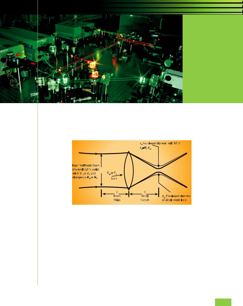
M2, or Beam Propagation Ratio, is a value that indicates how close a laser is to being a single mode TEM00 beam, which in turn determines how small a beam
waist can be focused. For the perfect Gaussian TEM00 condition the M2 equals 1.
Figure 1. Characteristics of a laser beam as it passes through a focusing lens.
For a laser beam propagating through space, the equation for the divergence, v, of an unfocused beam is given by:
than 1, and thus the minimum beam waist will be larger by the M² factor.
For a pure Gaussian TEM00 beam M² equals 1, and thus has no impact on the calculation. The calculation of the minimal beam spot is then:
d0 = 4l/PD0
Again with M² equal to 1, the focused spot is diffraction limited. For real beams, M² will be greater
HOW IS M2 MEASURED?
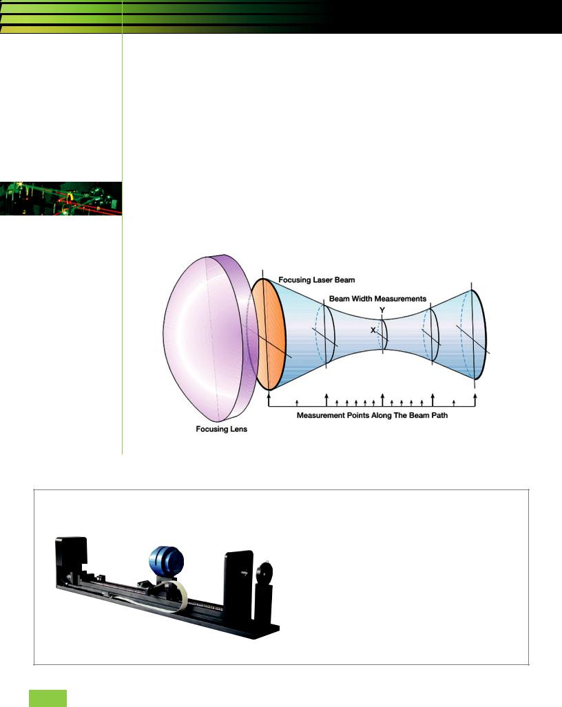
M² cannot be determined from a single beam profile measurement. The ISO/DIS 11146 requires that M² be calculated from a series of measurements as shown in the figure below. M² is measured on real beams by focusing the beam with a fixed position lens of known focal length, and then measuring the characteristics of the artificially created beam waist and divergence.
To provide an accurate calculation of M², it is essen- continued on page 10
B E A M P R O F I L I N G Page 9
WHAT IS M2
continued from page 9
tial to make at least 5 measurements in the focused beam waist region, and at least 5 measurements in the far fields, two Rayleigh ranges away from the waist area. The multiple measurements ensure that the minimum beam width is found. In addition, the multiple measurements enable a “curve fit” that improves the accuracy of the calculation by minimizing measurement error at any single point. An accurate calculation of M² is made by using the data from the multiple beam width measurements at known distances from a lens, coupled with the known characteristics of the focusing lens.
M2 MEASUREMENT SOLUTIONS
Ophir-Spiricon and Photon have a number of solutions for the measurement of M² ranging from simple manual processes to fully automated dedicated instruments, depending on the frequency of the need to measure M² of lasers and laser systems. We have a system that will meet most needs, whether for research and development of new laser systems, manufacturing quality assurance, or maintenance and service of existing systems.
Figure 2. Multiple beam width measurements made by M²-200 and M²-200s
Automated M2 Measurements for CO2
|
Ophir Photonics, global leader in precision laser |
|
measurement equipment and a Newport Corporation |
|
brand, introduces the NanoModeScan M2 Laser Beam |
|
Propagation Analyzer for quantitative measurement and |
|
viewing of high-power CO2 laser beams. The system is |
|
easy to set up and align, requiring little or no attenuation, |
|
making M2 measurements in as little as 20 seconds. |
Ophir-Spiricon LLC |
(866) 755-5499 |
sales@us.ophiropt.com |
www.ophiropt.com/photonics |
Page 10 O P H I R P H O T O N I C S , W W W . O P H I R O P T . C O M / P H O T O N I C S