

8. FOCUSSING AND TARGET SIGHTING
• When sighting the target,strong light shining directly into the
Caution
objective lens may cause the instrument to malfunction.Protect the objective lens from direct light by attaching the lens hood.
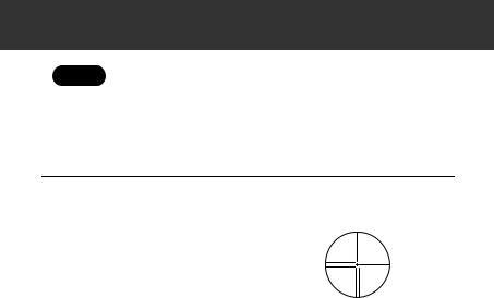
•Observe to the same point of the reticle when the telescope face is changed.
PROCEDURE
1.Focus on the reticle
Look through the telescope eyepiece at a bright and featureless background.
Turn the eyepiece clockwise, then
counterclockwise little by little until just before the reticle image becomes focussed.
Using these procedures, frequent reticle refocussing is not necessary, since your eye is focussed at infinity.
2.Sight the target
Loosen the vertical and horizontal clamps, then use the peep sight to bring the target into the field of view. Tighten both clamps.
3.Focus on the target
Turn the telescope focussing ring to focus on the target.
Turn the vertical and horizontal fine motion screws to align the target with the reticle.
The last adjustment of each fine motion screw should be in the clockwise direction.
4.Readjust the focus until there is no parallax
Readjust the focus with the focussing ring until there is no parallax between the target image and the reticle.
24

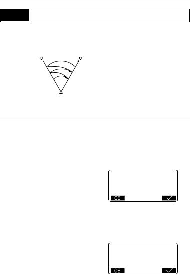
8. FOCUSSING AND TARGET SIGHTING
Eliminating parallax
This is the relative displacement of the target image with respect to the reticle when the observer’s head is moved slightly before the eyepiece. Parallax will introduce reading errors and must be removed before observations are taken. Parallax can be removed by refocussing the reticle.
25
9.POWER ON
Setting “V manual”: “24.1 Changing Instrument Options z Settings in Config Mode”.
PROCEDURE
1.Power on Press {ON}.
When the power is switched on, a self-check is run to make sure the instrument is operating normally.
•When “V manual” is set to “Yes”, the display appears as at right.
Manually indexing the vertical circle by face left, face right measurements: 30.1 Manually Indexing the Vertical Circle by Face Left, Face Right Measurement
0SET
Take F1 ZA V1
HAR 0°00'00"
After that, Meas Mode screen appears.
If “Out of range” is displayed, the instrument tilt sensor is indicating that the instrument is out of level. Level the instrument once again and the horizontal and vertical angles will be displayed.
Meas |
PC |
-30 |
|
|
S |
ppm |
0 |
|
|
|
|
|
|
|
|
|
|
|
|
ZA |
80°30'15" |
|
|
|
HAR |
120°10'00" |
|
P1 |
|
|
|
|||
•When “Resume” in “Instr. config” is set to “On”, the screen previous to power
off is displayed.
“24.1 Changing Instrument Options z Settings in Config Mode”
•“Tilt crn” in “Obs. condition” should be set to “No” if the display is unsteady due
to vibration or strong wind.
“24.1 Changing Instrument Options z Settings in Config Mode”
26

10. ANGLE MEASUREMENT
This section explains the procedures for basic angle measurement.
10.1Measuring the Horizontal Angle between Two Points (Horizontal Angle 0°)
Use the "0SET" function to measure the included angle between two points. The horizontal angle can be set to 0 at any direction.
PROCEDURE
1. Sight the first target.
2.In the first page of the Meas mode screen, press  .
.
 will flash, so press
  again.
The horizontal angle at the first target becomes 0°.
3.Sight the second target.
1st target |
|
|
|
|
|
|
Instrument Station |
||||
Meas |
PC |
-30 |
|
|
|
S |
ppm |
0 |
|
|
|
|
|
|
|
|
|
|
|
|
|
|
|
ZA |
89°59'50" |
|
|
|
|
HAR |
0°00'00" |
|
P1 |
|
|
|
|
|
|||
2nd target
The displayed horizontal angle |
Meas |
PC |
-30 |
|||
(HAR) is the included angle |
||||||
S |
ppm |
0 |
||||
between two points. |
|
|
|
|
||
|
|
|
|
|||
|
|
|
|
|||
|
ZA |
89°59'50" |
|
|
|
|
|
HAR |
117°32'20" |
|
|
||
|
|
P1 |
||||
|
|
|
||||
27

10.ANGLE MEASUREMENT
10.2Setting the Horizontal Angle to a Required Value (Horizontal Angle Hold)
You can set the horizontal angle in certain direction to any required value and then measure the angle from the direction.
PROCEDURE
1.Sight the first target.
2.In the second page of the Meas
mode screen, press  . Select "H angle."
3.Enter the angle you wish to set, then press {  }.
}.
The value that is input as the horizontal angle is displayed.
4.Sight the second target.
The horizontal angle from the second target to the value set as the horizontal angle is displayed.
HAR: |
125 |
|
|
|
|
|
|
Meas |
PC |
-30 |
|
|
|||
S |
ppm |
0 |
|
|
|||
|
|
|
|
|
|
||
ZA |
89°59'50" |
|
|
|
|
|
|
HAR |
117°32'20" |
|
|
|
|||
|
P1 |
||||||
|
|
|
|
|
|
|
|
•Pressing  performs the same function as above.
Press  to set the displayed horizontal angle. Then, set the angle that is in hold status to the direction you require.
Allocating  : “24.2 Allocating Key Functions”
28
10. ANGLE MEASUREMENT
10.3Horizontal Angle Repetition
To find the horizontal angle with greater precision, perform repetition measurement.
1st target (BS)
3rd meas. starts 2nd meas. starts
1st meas. starts
2nd target (FS)
 3rd meas. end (average of three measurements is displayed) 2nd meas. end (average of two measurements is displayed)
1st meas. end (the angle between two points is displayed)
Station
PROCEDURE
1.Allocate the  softkey to the Meas mode screen.
“24.2 Allocating Key Functions”
2.Press  .
.
The horizontal angle becomes 0°.
3.Sighting the first target, press
 .
.
4.Sighting the second target, press
 .
.
5.Sighting the first target a second time, press  .
.
6.Sighting the second target a
second time, press  .
.
The added value of the horizontal angle is displayed on the second line "HARp" and the average value of the horizontal angle is displayed on the fourth line "Ave.".
Repetition
HARp 0°00'00"
Reps. 0
Ave.
Take BS
Repetition
HARp 110°16'20"
Reps. 2
Ave. 50°38'10"
Take BS
29

10.ANGLE MEASUREMENT
•Return to the previous measurement of the first target and redo it:  .
.
(Effective when the display shows "Take BS")
7.When continuing the repetition measurement, repeat steps 4 to 5.
8.When the repetition measurement is completed, press {ESC}.
•It is also possible to perform repetition measurement when  on page 2 of the Meas mode screen is pressed to enter <Menu>, then "Repetition" is selected without allocating the function key.
10.4Angle Measurement and Outputting the Data
The following explains angle measurement and the features used to output measurement data to a computer or peripheral equipment.
Comms setup: “24.1 Changing Instrument Options”• ““l Settings in Config Mode (items set, options, and input range)”” on page 103. Connecting with other devices, Command operation: “23. OUTPUTTING JOB DATA”.
PROCEDURE
1.Connect SET and host computer.
2.Allocate the  softkey to the Meas mode screen.
“24.2 Allocating Key Functions”
3.Sight the target point.
4.Press  and select "Angle Data."
Output measurement data to peripheral equipment.
30