

Figure 4 Flat Earth Reference Coordinate system
Inertial Navigation Unit
The inertial navigation unit (INU) of an aircraft is designed to maintain a local inertial reference frame. However, the origin of this reference frame is centered within the INU which is not usually located at the aircraft center of gravity. Therefore, during dynamic manoeuvres, the INU orientation, acceleration and velocity data must be corrected for fuselage bending and the offset from the center of gravity in order to determine the actual values in the true inertial reference frame. Additionally, the INU coordinate system may not be aligned with the inertial (flat-Earth) frame defined above.

Figure 5 F-16 Inertial Navigation Unit Coordinate System
COORDINATE SYSTEM TRANSFORMATION
With each of the aircraft coordinate systems defined, we can now develop the transformations between each system.
BODY-FIXED FORM STABILITY
The transformation to the body-fixed reference frame from the stability includes a single Rotation about the ys – axis through the angle of attack, α, as shown in Fig. 6.
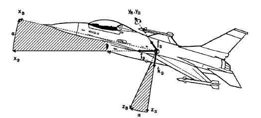
Figure 6 Stability to Body-Fixed Coordinate System transformation through the Angle of Attack, α
To
transform
![]() expressed in the stability coordinates into body coordinates:
expressed in the stability coordinates into body coordinates:
![]()
where

To transform defined in body-fixed coordinated to stability coordinates:
![]()
where

BODY-FIXED FROM INERTIAL
The transformation to the body-fixed reference frame from the inertial (flat Earth) reference frame is accomplished by three rotations through the angles ψ, θ, Φ, as shown in Fig.7. These angles are called Euler angles. The three rotations are not commutative, that is, they must be in the specified order to achieve the desired aircraft orientation.

Figure 7 Inertial to Body fixed Coordinate System Transformation through Euler angles
The first rotation is about the ZI –axis through the yaw or heading angle, ψ, to the first intermediate coordinate system x1, y1, z1, as shown in Figure 8. Thus, to transform a vector defined in the inertial reference frame into coordinates of the first intermediate frame:
![]() ,
where
,
where
 (1)
(1)

Figure 8 Inertial 1st Intermidiate Coordinate System ransformation through the Heading Angle, ψ
The second
rotation is about the y1
– axis through the pitch angle, θ, to the second intermediate
coordinate system x2,y2,z2,
as shown in Fig. 9. Defining
![]() in terms of this system:
in terms of this system:
![]() ,
where
,
where
 (2)
(2)

Figure 9 1st to 2nd Intermediate Coordinate System Transformation through the Pitch Angle, θ
The final
third rotation is about the x2-
axis through the roll angle, Φ, to the body –fixed coordinate
system (Fig.10). Defining
![]() in terms of the body system:
in terms of the body system:
![]() ,
where
,
where
 (3)
(3)

Figure 10 3rd Intermediate to Body-Fixed Coordinate System Transformation through the Roll angle, Φ
Now, to perform the entire transformation to the body-fixed coordinate system from the inertial, we simply multiply the rotation matrices (eq. 3, 2, 1) to obtain the desired transformation matrix:
![]()
where

Note: c=co sans s=sin.
Because they are orthogonal, each of the martices defined above in the equations have the unique property that the transpose of the matrix is equal to the inverse.
![]() .
.
Thus, if we wish to transform a vector expressed in body-fixed coordinates into the inertial frame:
![]()
WIND FROM STABILITY
The transformation to the wind reference frame from the stability includes a single rotation through the angle of sideslip, β, as shown in Fig. 11. To transform expressed in the stability coordinates into wind coordinates:
![]()
where
 .
.

Figure 11Stability to Wind Coordinate System Transformation through the Angle of Sideslip, β
To transform defined in wind coordinates to stability coordinates:
![]()
and

WIND FROM BODY-FIXED
The transformation to wind coordinates from the body-fixed system includes the two rotations through α and β as shown previously in Figure 3. To transform expressed in body coordinates into wind coordinates:
![]()
where
To transform back into body coordinates:
![]() ,
,
where

AERODYNAMIC ANGLES
The angle between the velocity vector and the plane of symmetry, measured in the plane xw - yw, is called sideslip angle and is denoted by the symbol β. Sideslip is positive when the relative wind is from right of the plane of symmetry, as shown in Figure 12.
Consider
the projection of the velocity vector
![]() into the plane of symmetry, and assume some body-fixed coordinate
system has been defined. The angle between this projection and xb
axis
is called the angle-of-attack and is given the symbol α. It is
positive when the relative wind is from below the xb
axis as shown in figure 13.
into the plane of symmetry, and assume some body-fixed coordinate
system has been defined. The angle between this projection and xb
axis
is called the angle-of-attack and is given the symbol α. It is
positive when the relative wind is from below the xb
axis as shown in figure 13.

Figure 12 Sideslip angle, β. The axis yb and velocity vector lie in the plane of the page
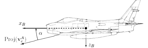
Figure 13 Angle-of Attack, α. Plane of the page is the aircraft plane of symmetry, xb-zb. Proj ( ) onto the plane of symmetry.