Figure 3-4 Correct mesh of spiral bevel gear
(Contact patch with no load)
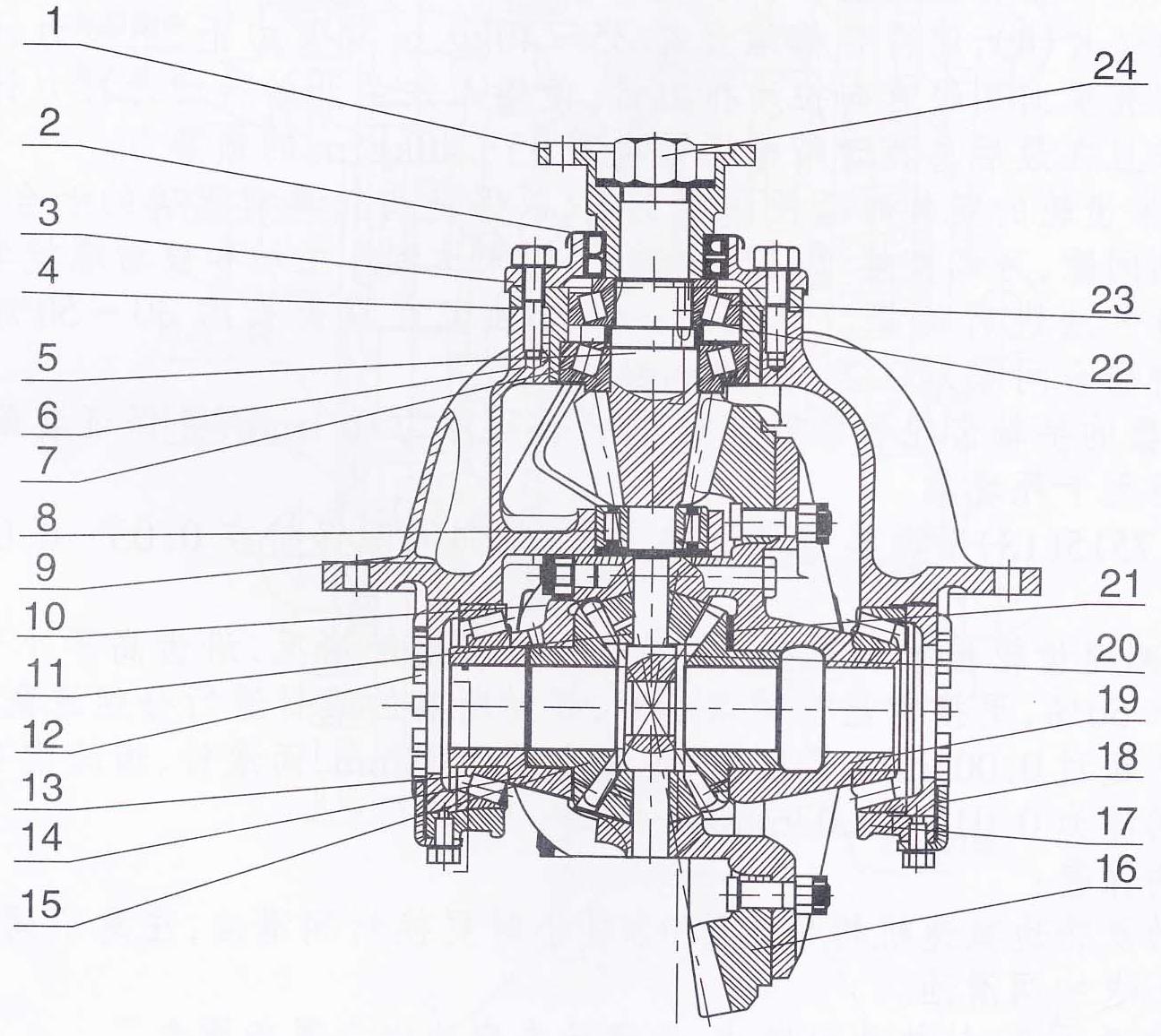
Figure 3-5 Final drive
1. Input flange |
9. Carrier |
17. Bearing cover |
2. Seal FB62×93×13 |
10. Bevel gear spacer |
18. Lock washer |
3. Seal cover |
11. Bevel gear |
19. Right differential case |
4. Shims |
12. Adjusting nut |
20. Spider |
5. Spiral pinion |
13. 7515 bearing 75×130×33.25 |
21. Axle shaft gear spacer |
6. Bearing bush |
14. Left differential case |
22. Shims |
7. 31311 bearing 55×120×31.5 |
15. Axle shaft gear |
23. 31310 bearing 50×110×29.25 |
8. 92606 bearing 30×72 × 27 |
16. Spiral bevel gear |
24. Lock nut |
5. Hydraulic Steering System
Combined flow of two pumps is adopted in the hydraulic steering system and the implement hydraulic system.
The hydraulic steering system consists of steering gear, priority valve, steering cylinder, steering pump, oil pipes and oil tank (shared with implement system). Refer to Figure 3-6 hydraulic diagram of steering system.
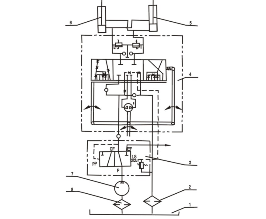
Figure 3-6 Steering system schematic diagram
1. Oil tank 2. Oil Suction Strainer 3. Priority valve 4. Steering gear BZZ5-800
5, 6. Left/right steering cylinder 7. Steering pump 8. Oil return screen
5.1 Working principle of steering system:
The pressure from oil pump flows to the priority valve, then to the steering gear at the first priority so that stable steering can be assured in spite of load, pressure, turning speed of steering wheel, engine speed. When the engine runs at high speed and the steering wheel is turned slowly or not turned, the priority valve makes the superfluous oil flow to the implement hydraulic system so as to make full use of oil. So the hydraulic efficiency is higher and the total displacement of pumps can be reduced.
A check valve is mounted in the inlet pipe of the steering gear to prevent retroaction of steering wheel caused by oil flowing backwards from the steering cylinder to the steering gear. When the steering wheel is turned clockwise, the oil flows to the small chamber of the right steering cylinder and the big chamber of the left steering cylinder via the steering gear so that the wheel loader makes right turns.
When the steering wheel is turned counter clockwise, the oil flows to the small chamber of the left steering cylinder and the big chamber of the right cylinder via the steering gear so that the wheel loader makes left turns. If obstacle is encountered or the turning limit is reached, the relief valve in the priority valve will be opened for relief when the system pressure exceeds 16MPa. The oil flows to the oil tank and overload is prevented.
5.2 Main parts in the steering system
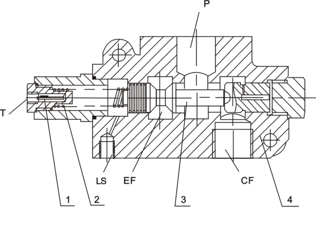
5.2.1 VLE-150 priority valve (Figure 3-7)
Nominal pressure: 16MPa
Nominal flow rate: 150 L/min
When the steering gear is in neutral position, the oil from the priority valve flows to the LS port via the orifice in the steering gear and acts on one side of the priority valve. The oil from the internal hole of priority valve stem will act on the other side (PP port). The pressure at the PP port of priority valve is stronger than the sum of pressure at LS port and the spring force so that only a little oil flows to the steering gear via CF port. The rest of the oil from steering pump flows to the implement hydraulic system via EF port.
When the steering is not at neutral position, the pressure at LS port rises and makes the stem of priority valve move towards the PP port so that the oil from the steering pump is supplied to the steering gear to realize the steering.