


Chapter 1 Hardware Installation
1-1 Installation Precautions
The motherboard contains numerous delicate electronic circuits and components which can become damaged as a result of electrostatic discharge (ESD). Prior to installation, carefully read the user's manual and follow these procedures:
•• Prior to installation, make sure the chassis is suitable for the motherboard.
•• Prior to installation, do not remove or break motherboard S/N (Serial Number) sticker or warranty sticker provided by your dealer. These stickers are required for warranty validation.
•• Always remove the AC power by unplugging the power cord from the power outlet before installing or removing the motherboard or other hardware components.
•• When connecting hardware components to the internal connectors on the motherboard, make sure they are connected tightly and securely.
•• When handling the motherboard, avoid touching any metal leads or connectors.
•• It is best to wear an electrostatic discharge (ESD) wrist strap when handling electronic components such as a motherboard, CPU or memory. If you do not have an ESD wrist strap, keep your hands dry and first touch a metal object to eliminate static electricity.
•• Prior to installing the motherboard, please have it on top of an antistatic pad or within an electrostatic shielding container.
•• Before unplugging the power supply cable from the motherboard, make sure the power supply has been turned off.
•• Before turning on the power, make sure the power supply voltage has been set according to the local voltage standard.
•• Before using the product, please verify that all cables and power connectors of your hardware components are connected.
•• To prevent damage to the motherboard, do not allow screws to come in contact with the motherboard circuit or its components.
•• Make sure there are no leftover screws or metal components placed on the motherboard or within the computer casing.
•• Do not place the computer system on an uneven surface.
•• Do not place the computer system in a high-temperature environment.
•• Turning on the computer power during the installation process can lead to damage to system components as well as physical harm to the user.
•• If you are uncertain about any installation steps or have a problem related to the use of the product, please consult a certified computer technician.
- 5 -
1-2 |
Product Specifications |
|||
|
|
|
|
|
|
CPU |
|
Support for Intel® Core™ i7 processors/Intel® Core™ i5 processors/ |
|
|
|
|
Intel® Core™ i3 processors/Intel® Pentium® processors/Intel® Celeron® processors |
|
|
|
|
in the LGA1155 package |
|
|
|
L3 cache varies with CPU |
||
|
Chipset |
|
Intel® Z77 Express Chipset |
|
|
Memory |
|
4 x 1.5V DDR3 DIMM sockets supporting up to 32 GB of system memory |
|
|
|
|
|
* Due to a Windows 32-bit operating system limitation, when more than 4 GB of physical |
|
|
|
|
memory is installed, the actual memory size displayed will be less than the size of |
|
|
|
|
the physical memory installed. |
|
|
Dual channel memory architecture |
||
|
|
|
Support for DDR3 1600/1333/1066 MHz memory modules |
|
|
|
|
Support for non-ECC memory modules |
|
|
|
|
Support for Extreme Memory Profile (XMP) memory modules |
|
|
Onboard |
|
Integrated Graphics Processor: |
|
|
Graphics |
|
- |
1 x DVI-D port, supporting a maximum resolution of 1920x1200 |
|
|
|
|
* The DVI-D port does not support D-Sub connection by adapter. |
|
|
|
- |
* Simultaneous output for DVI-D and the MDP2 Thunderbolt port is not supported. |
|
|
|
1 x HDMI port, supporting a maximum resolution of 1920x1200 |
|
|
|
|
Intel® DSL3510L chip: |
|
|
|
|
- |
2 x Thunderbolt ports (MDP1/MDP2) for Mini-DisplayPort and Thunderbolt |
|
|
|
|
monitor(s), supporting a maximum resolution of 2560x1600. |
|
|
|
|
* If a monitor is connected to the DVI-D port, the MDP2 Thunderbolt port can support |
|
|
|
|
Thunderbolt storage device(s) only. |
|
|
|
|
* Because of the limited I/O resources of the PC architecture, the number of Thunderbolt |
|
|
|
|
devices that can be used is dependent on the number of the PCI Express and PCI |
|
|
|
|
devices being installed. (Refer to Chapter 1-7, "Back Panel Connectors," and Chapter |
|
|
|
|
2, "Peripherals\Intel(R) Thunderbolt" for more information.) |
|
Audio |
|
Realtek® ALC892 codec |
|
|
|
|
High Definition Audio |
|
|
|
|
2/4/5.1/7.1-channel |
|
|
|
|
Support for S/PDIF In/Out |
|
|
LAN |
|
Intel® GbE LAN chip (10/100/1000 Mbit) |
|
|
Expansion Slots |
|
1 x PCI Express x16 slot, running at x16 (PCIEX16) |
|
|
|
|
|
* For optimum performance, if only one PCI Express graphics card is to be installed, |
|
|
|
|
be sure to install it in the PCIEX16 slot. |
|
|
1 x PCI Express x16 slot, running at x8 (PCIEX8) |
||
|
|
|
(The PCIEX16 and PCIEX8 slots conform to PCI Express 3.0 standard.) |
|
|
|
|
|
* Whether PCI Express 3.0 is supported depends on CPU and graphics card |
|
|
|
|
compatibility. |
|
|
|
|
* The PCIEX8 slot shares bandwidth with the PCIEX16 slot. When the PCIEX8 slot |
|
|
|
|
is populated, the PCIEX16 slot will operate at up to x8 mode. |
|
|
2 x PCI Express x1 slots |
||
|
|
|
(All PCI Express x1 slots conform to PCI Express 2.0 standard.) |
|
|
Multi-Graphics |
|
Support for AMD CrossFire™/NVIDIA® SLI™ technology |
|
|
Technology |
|
|
|
|
Storage Interface |
|
Chipset: |
|
|
|
|
- |
2 x SATA 6Gb/s connectors (SATA3 0/1) supporting up to 2 SATA 6Gb/s |
|
|
|
- |
devices |
|
|
|
4 x SATA 3Gb/s connectors (SATA2 2~5) supporting up to 4 SATA 3Gb/s |
|
|
|
|
|
devices |
- 6 -
Storage Interface |
|
- |
Support for RAID 0, RAID 1, RAID 5, and RAID 10 |
|
|
|
* When a RAID set is built across the SATA 6Gb/s and SATA 3Gb/s channels, the |
|
|
|
system performance of the RAID set may vary depending on the devices being |
|
|
|
connected. |
USB |
|
Chipset: |
|
|
|
- |
Up to 4 USB 3.0/2.0 ports (2 ports on the back panel, 2 ports available |
|
|
|
through the internal USB header) |
|
|
- |
* In Windows XP, the Intel® USB 3.0 ports can support up to USB 2.0 transfer speed. |
|
|
Up to 10 USB 2.0/1.1 ports (4 ports on the back panel, 6 ports available |
|
|
|
|
through the internal USB headers) |
IEEE 1394 |
|
T.I®. XIO2213B chip: |
|
|
|
- |
Up to 2 IEEE 1394b ports available through the internal IEEE 1394b |
|
|
- |
headers |
|
|
Up to 1 IEEE 1394a port on the back panel |
|
Thunderbolt |
|
Intel® DSL3510L chip: |
|
|
|
- |
2 Thunderbolt ports on the back panel |
Internal |
1 x 24-pin ATX main power connector |
||
Connectors |
1 x 4-pin ATX 12V power connector |
||
|
2 x SATA 6Gb/s connectors |
||
|
4 x SATA 3Gb/s connectors |
||
|
1 x CPU fan header |
||
|
2 x system fan headers |
||
|
1 x front panel header |
||
|
1 x front panel audio header |
||
|
1 x S/PDIF Out header |
||
|
1 x S/PDIF In header |
||
|
1 x USB 3.0/2.0 header |
||
|
3 x USB 2.0/1.1 headers |
||
|
2 x IEEE1394b headers |
||
|
1 x Clear CMOS jumper |
||
|
1 x Trusted Platform Module (TPM) header |
||
Back Panel |
1 x IEEE1394a port |
||
Connectors |
2 x Thunderbolt ports |
||
|
1 x DVI-D port |
||
|
1 x HDMI port |
||
|
2 x USB 3.0/2.0 ports |
||
|
4 x USB 2.0/1.1 ports |
||
|
1 x RJ-45 port |
||
|
1 x optical S/PDIF Out connector |
||
|
5 x audio jacks (Center/Subwoofer Speaker Out, Rear Speaker Out, Line In, |
||
|
|
Line Out, Mic In) |
|
I/O Controller |
iTE® I/O Controller Chip |
||
Hardware
Monitor
System voltage detection
CPU/System temperature detectionCPU/System fan speed detectionCPU overheating warning
CPU/System fan fail warningCPU/System fan speed control
*Whether the CPU/system fan speed control function is supported will depend on the CPU/system cooler you install.
- 7 -
BIOS |
|
2 x 64 Mbit flash |
|
|
Use of licensed AMI EFI BIOS |
||
|
Support for DualBIOS™ |
||
|
PnP 1.0a, DMI 2.0, SM BIOS 2.6, ACPI 2.0a |
||
Bundled |
|
Intel® Rapid Start Technology |
|
Software |
|
Intel® Smart Connect Technology |
|
|
|
Intel® Smart Response Technology |
|
Operating |
Support for Windows 8/7/XP |
||
System |
|||
|
|
||
Form Factor |
|
Micro ATX Form Factor; 24.4cm x 24.4cm |
|
|
|
|
|
1-3 |
Installing the CPU |
|
|
Read the following guidelines before you begin to install the CPU: |
|
|
•• |
Make sure that the motherboard supports the CPU. |
|
•• |
Always turn off the computer and unplug the power cord from the power outlet before installing the |
|
•• |
CPU to prevent hardware damage. |
|
Locate the pin one of the CPU. The CPU cannot be inserted if oriented incorrectly. (Or you may |
|
|
•• |
locate the notches on both sides of the CPU and alignment keys on the CPU socket.) |
|
Apply an even and thin layer of thermal grease on the surface of the CPU. |
|
|
•• |
Do not turn on the computer if the CPU cooler is not installed, otherwise overheating and damage |
|
•• |
of the CPU may occur. |
|
Set the CPU host frequency in accordance with the CPU specifications. It is not recommended |
|
|
|
that the system bus frequency be set beyond hardware specifications since it does not meet the |
|
|
standard requirements for the peripherals. If you wish to set the frequency beyond the standard |
|
|
specifications, please do so according to your hardware specifications including the CPU, graphics |
|
|
card, memory, hard drive, etc. |
Installing the CPU
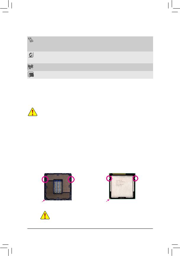
Locate the alignment keys on the motherboard CPU socket and the notches on the CPU.
|
LGA1155 CPU Socket |
|
LGA1155 CPU |
Alignment Key |
Alignment Key |
Notch |
Notch |
|
|
Pin One Corner of the CPU Socket |
Triangle Pin One Marking on the CPU |
Do not remove the CPU socket cover before inserting the CPU. It may pop off from the load plate automatically during the process of re-engaging the lever after you insert the CPU.
- 8 -