

7.6 Equipment for dyeing from organic solvents
Solvent dyeing plant can be generally classified into two categories:
• Non-continuous plant
• Continuous plant
Non-continuous plant Drum dyeing machines (without pressure).
When we first took up this new dyeing method, we used conventional dry-cleaning equipment of the drum type for non-continuous dyeing. Such machines, which are supplied by a variety of manufacturers, have a capacity of 10-200 kg.
The basic principle and also the advantage of such plant is that the material to be dyed-preferably fully fashioned goods and knitted goods-is introduced into the machine in the dry state, and that it also leaves the machine in dry condition after undergoing all the processing operations, such as scouring, degreasing, dyeing or impregnating ("dry-to-dry").
The central part of the construction of a drum dry-cleaning machine is the drum casing and the revolving drum which it encloses. Basically, the construction is similar to that of the well-known household washing machines. The drum casing is generally made of galvanized sheet iron, while the drum is made of stainless steel. Soon after we had started our dyeing experiments, we found that the galvanized machine parts were unsuitable for dyeing from perchloroethylene, and we had to replace them by stainless steel casings.
New machines based on the principles of dry-cleaning plant were developed especially for dyeing, by several manufacturers, particularly by Bohler & Weber KG, Augsburg/Germany. In the course of the past few years, these machines were developed on a pilot plant scale for small charges and for research work (Fig. 1). The Bowe prototype LFM 12 (maximum load 12 kg) differs from normal dry-cleaning plant in these points:
-compact construction, using stainless steel
-drum casing and feeding tank can be heated
-still with superdimensioned distillation capacity
The LFM 12 machine can be used both for dyeing from pure perchloroethylene and from perchloroethylene/water emulsions. Control can be fully automatic by means of a programme card, or by hand. The liquor ratios can be varied from 4:1 to 10:1. During the process, the liquor is circulated several times in 1 minute. Treatment time is 75 to 100 minutes, including pretreatment, dyeing, rinsing, aftertreatment and drying. Dyeing experiments carried out on the LFM 12 have shown that the machine is easy to handle and that shades, once they have been adjusted, are easy to reproduce. We are informed that besides Bowe, other manufacturers are also concerned with the development of pressure-free solvent drum dyeing machines:
Seco Maschinenbau GmbH Co. KG; Rottenburg a. M. (Germany); Neil & Spencer Ltd., Leatherhead (U.K.); Brown & Green, Ltd. (U.K); Specima (Germany); Eisenach (Germany); Carborundum Co., Commercial Filters; Division, Lebanon (U.S.A.); Impianti Everest. Calcaterra & Co; Rovagnasco di Segrate (Italy); Maestrelli, Milan (Italy); Donini, Bologna (Italy).
Pressure dyeing machines.
Trials in Leverkusen revealed that it is not always possible to get the best results when using solvent dyeing machines which I work without pressure. For example, in the case of dry-spun acrylics it is practically impossible to get complete bath exhaustion within a short treatment time by the emulsion method. Furthermore, to get high bath exhaustion, it will be absolutely necessary to add small quantities of water when dyeing polyester with certain selected dyestuffs. Under such dyeing conditions, pressure must be applied when dyeing, either to ensure that the emulsions remain stable, or to get high temperatures of approx. 120°C. Owing to the azeotropic boiling point of 87 °C of the water/perchloroethylene mixtures under normal pressure, best possible dyeing conditions can only be attained in plant operating under pressure.
Pressure drum dyeing machine.
For the reasons we have just stated, we designed a laboratory-scale pressure drum dyeing machine which was set up in Leverkusen. The necessary conditions can be monitored by means of a special control arrangement. (Figs. 7.9 and 7.10) This construction was preceded by extensive laboratory and conventional pilot plant trials, such as cheese dyeing (package dyeing) machines and combined H.T. winch beck and paddle-dyeing machines. Only slight modifications were required to adapt these machines for solvent dyeing. The experience we collected during this work went into the construction of the drum dyeing machines:
- temperature and pressure of the bath must remain constant
- in emulsion dyeing, e.g. perchloroethylene/water, the water component must not evaporate, or care must be taken to re-emulsify the evaporated and condensed water.
To ensure maximum economy and safety, pretreatment, dyeing, rinsing, hydro-extraction, after treatment and drying are effected in the closed system of the drum dyeing machine until all processing operations have been completed. The drum is overhung-mounted in a compression-proof beck (dyeing vessel) and is driven via a V-belt by an infinitely variable geared engine. A mechanical seal on the drum shaft at the point where it passes through the dyeing machine housing prevents the exit of solvent vapour. Half-section pipes are welded on the circumference and the back plate of the dyeing vessel. These are covered by a plate so that two separate channels are formed, one of which is used for steam heating, the other for water cooling. The heat transfer areas in both channels are of different size. The heating and cooling capacities can be modified by interchanging the steam and water supply, all other conditions remaining the same. There is no arrangement for direct heating.
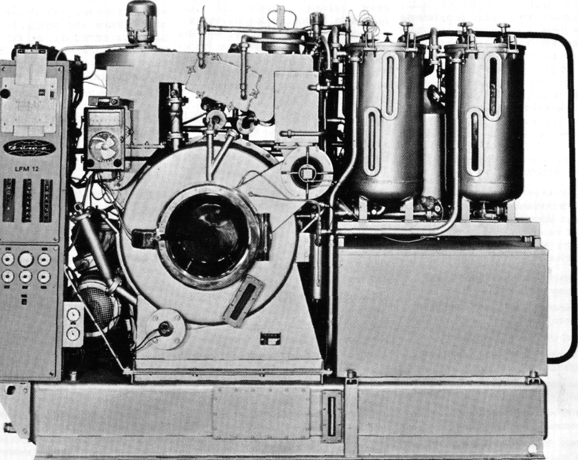
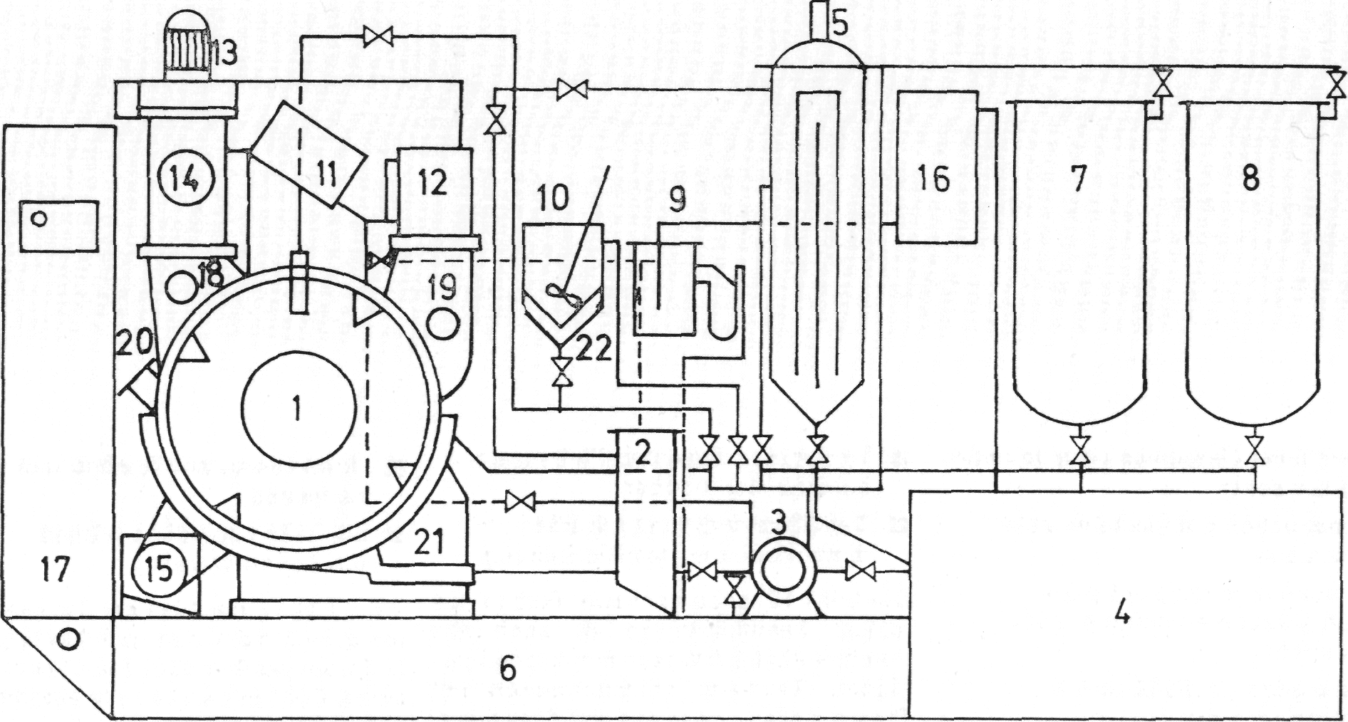
Fig. 7.9. View and schematic representation of the solvent dyeing machine LFM 12 by Bowe, (Augsburg, Germany):
1 - dyeing drum. 2 - pre-filter, 3-pump; 4 – still; 5 - Bowe expander filter, 6 - tank for clean solvent; 7 - tank I; 8 – tank II; 9 - water separator; 10 - dyestuff feed tank; 11 - air-cooler; 12 - air-heater; 13 - fan motor; 14 - fiber waste trap;15 - drum drive; 16 - condenser, 17 – switchgear; 18 - circulating air flap; 19 - fresh air flap; 20 - sample compartment; 21 - drum heating; 22 - heating device for feed tank.
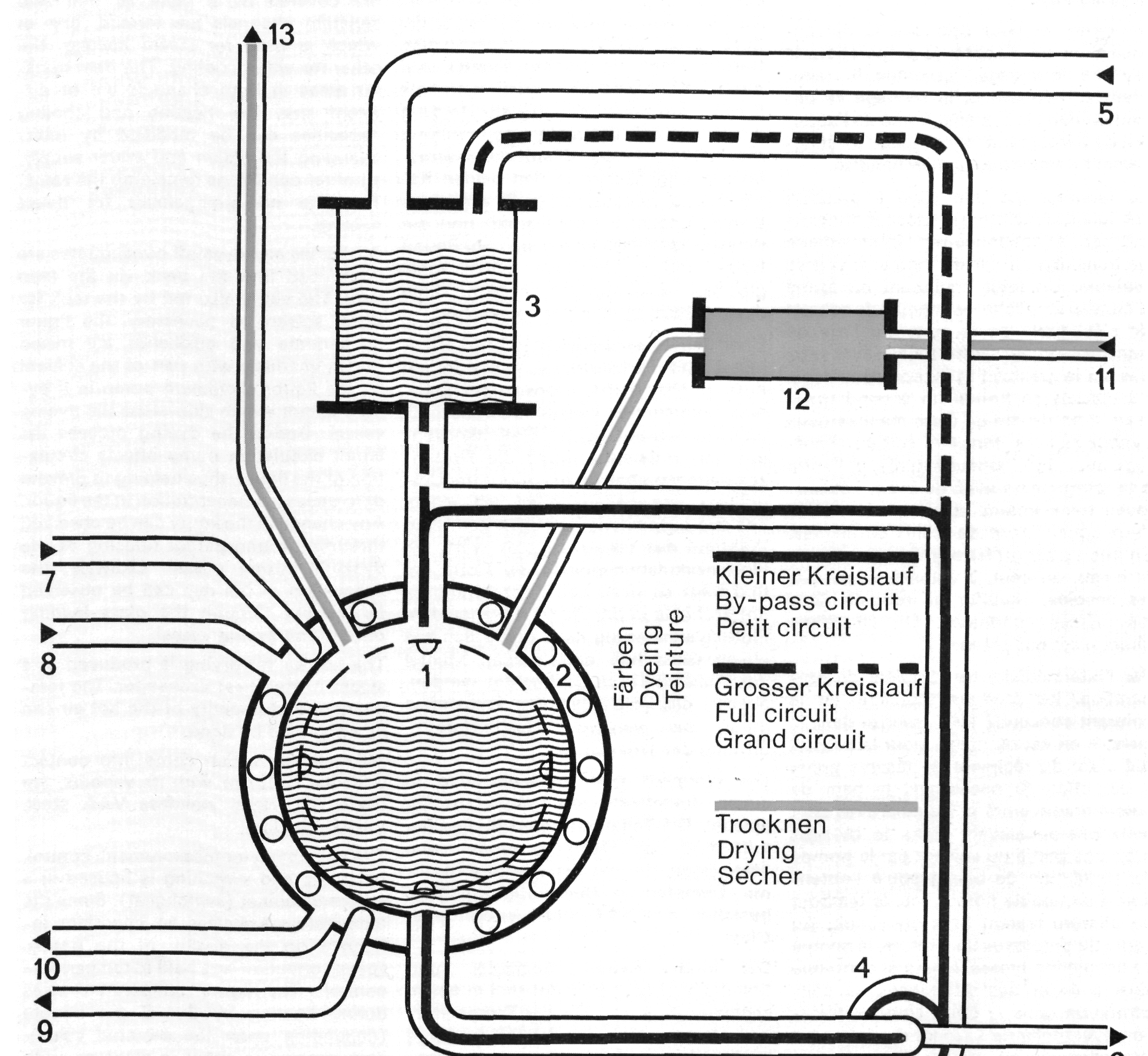
Fig. 7.10. Schematic drawing of the pressure drum dyeing machine (Bayer):
1 - dyeing drum; 2 - dyeing autoclave; 3 - feed tank, 4 - pump, 5 - from clean solvent tank, 6 - to tank for soiled perchloroethylene, 7 - steam conduit, 8 - cooling water conduit, 9 - condensed water discharge, 10 - cooling water discharge, 11 - fresh air for drying, 12 - heat exchanger. 13 - waste air.
Auxiliaries and dyestuff concentrates are introduced into the beck via the feed tank. The vat is also fed by the tank for clean solvent. If necessary, the liquor concentrate and auxiliaries are mixed homogeneously with part of the solvent by the liquor circulation pump in a bypass circuit which side-steps the dyeing vessel. During the dyeing process the liquor circulation pump effects circulation of the liquor, thus helping to prevent differences in concentration in the liquor. Any change in the liquor can be observed through the transparent housing of the dyestuff mixing vessel. Likewise, the exhaustion of the dye can be observed by looking through the glass loading door of the dyeing vessel. The hot air for drying is produced in a steam-heated heat exchanger. The temperature and quantity of the hot air can be controlled by hand. All materials which come into contact with the liquor or with its vapours, are made of special stainless V4A steel, Viton®, or glass.
The equipment for measurement, control, recording and switching is housed in a separate cabinet (switchgear). Since the temperature exercises an important influence on the quality of the goods, special attention was paid to temperature control: The liquor temperature rises during heating by 2-4°C per minute (depending upon the prorated value). This increase is either in steps or, with reflux cooling, linear. Conversely, the liquor and the goods can be cooled in an equally controlled manner. The following values are measured:
- Liquor temperature in the dyeing vessel
- Vapour temperature above the liquor in the beck
- Pressure in the dyeing vessel
- Quantity of circulated liquor the following factors are controlled:
- Liquor temperature in the dyeing vessel
- Pressure in the dyeing vessel (static pressure is regulated by hand)
The following values are recorded:
- Liquor temperature in the dyeing vessel
- Temperature of the vapour above the liquor in the dyeing vessel
- Quantity of circulated liquor
The following values are read from the drum dyeing apparatus:
- Liquor level from the gauge glass
- Pressure in the dyeing vessel
- Temperature of the hot air used for drying the goods
Technical data:
Load capacity: approx. 0.5 kg goods
Dyeing temperature: 1 30°C maximum
Pressure in the dyeing vessel: 4.0 atm. super-pressure (maximum) Liquor ratio: 8:1 to 30:1
Quantity of circulated liquor: 8 L per minute (maximum)
Speed of the drum: 50 to 540 r.p.m. Drum diameter: 300 mm 0
Capacity of dyeing vessel: 24 L
Heating: 6 atm. super-pressure saturated steam
Cooling: cooling water at room temperature
Compressed air: 4.0 atm. super-pressure