


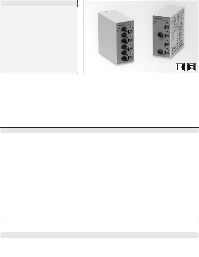
MULTIPLEXED AMPLIFIER SERIES
In an industry where most products resemble each other, we have strived to make sure that Telco only resembles Telco – in terms of quality, reliability, performance and ease-of-use. This is no different for the multiplexed amplifier series, which has withstood the test of time for that exact reason.
MULTIPLEXED AMPLIFIER SERIES |
MPA 21 |
|
|
Description
Operation mode and max sensing range:
Thru beam: 0-45 m Diffuse proximity: 0-3,5 m
230 V ac, 115 V ac, 24 V ac or 24 V dc supply voltage
Manual sensitivity adjustment
Adjustable on/off time delay
2 relays or 2 transistor outputs
Power, output and signal level indicators
Switch selectable light or dark function
Switch selectable long or short range
11-pole DIN socket connection
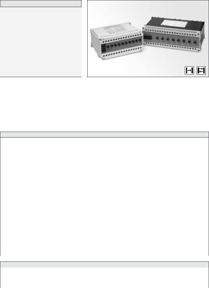
The MPA 21 is a 2-channel, multiplexed photoelectric amplifier, which is to be used in conjunction with 2 sets of remote transmitters LT and receivers LR, from the series 100, 110 and 120.
The 2 channels operate independently of each other with their own set of remote transmitter and receiver. The multiplexing function ensures that optical cross talk between channels is prevented.
The series offers a choice between 2 individual relays or 2 individual NPN/PNP transistor outputs, with or without an adjustable 0-3 sec on/off time delay.
This amplifier series offers manual sensitivity adjustment for each individual channel via integral potentiometers located on the front panel of the amplifier. Light or dark function and long or short range are switch selectable for each individual channel.
Technical Data
Supply voltage |
|
24 V dc, 24 V ac, 115 V ac or 230 V ac |
|
|
|
|
|
Voltage tolerance |
|
+/– 15 % |
|
|
|
|
|
Current consumption |
|
Max. 3 VA |
|
|
|
|
|
Output |
Relay |
1 open / 1 close, 250 V ac / 3 A, 120 V ac / 5 A |
|
Transistor |
|
||
40 mA / 30 V dc |
|||
|
|||
|
|
|
|
Power on indicator |
|
Green LED |
|
|
|
|
|
Output indicator |
|
Red LED |
|
|
|
|
|
Signal level indicator |
|
Green LED |
|
|
|
|
|
LR sensor failure indicator |
|
– |
|
|
|
|
|
LT sensor failure indicator |
|
– |
|
|
|
|
|
Sensor monitor LED drive |
|
– |
|
|
|
|
|
Hysteresis |
|
Approx. 35 % |
|
|
|
|
|
Operation frequency |
Relay |
9 Hz |
|
Transistor |
|
||
11 Hz |
|||
|
|||
|
|
|
|
Response time tON / tOFF |
Relay |
55 ms / 55 ms |
|
|
|
||
Transistor |
45 ms / 45 ms |
||
|
|||
|
|
|
|
Delay tON / tOFF |
MPA 21 A |
0 – 3 sec, adjustable |
|
Housing material |
|
Noryl |
|
|
|
|
Environmental Data
Temperature, operation |
– 10 to +50 ºC |
|
|
Temperature, storage |
– 40 to +80 ºC |
|
|
Sealing class |
IP 40 |
|
|
Approvals |
a b d |
|
|
REMOTE PHOTOELECTRIC SYSTEMS I 35
MPA 21 |
|
|
|
MULTIPLEXED AMPLIFIER SERIES |
|||
|
|
|
|
|
|
|
|
|
|
|
|
|
|
|
|
Available Types |
|
|
|
|
|
|
|
Model |
Connection |
Supply Voltage |
24 V dc |
24 V ac |
115 V ac |
230 V ac |
|
|
|
|
|
|
|||
Output |
|
Order Reference |
|
||||
|
|
|
|
||||
|
|
|
|
|
|
|
|
MPA 21 A |
|
2 individual relays |
MPA 21 A 503 |
MPA 21 A 502 |
MPA 21 A 501 |
MPA 21 A 500 |
|
On/Off delay |
11-pole DIN socket |
2 individual NPN/PNP |
MPA 21 A 603 |
MPA 21 A 602 |
MPA 21 A 601 |
MPA 21 A 600 |
|
|
|
|
|
|
|
||
MPA 21 B |
2 individual relays |
MPA 21 B 503 |
MPA 21 B 502 |
MPA 21 B 501 |
MPA 21 B 500 |
||
|
|||||||
|
|
|
|
|
|
||
|
2 individual NPN/PNP |
MPA 21 B 603 |
MPA 21 B 602 |
MPA 21 B 601 |
MPA 21 B 600 |
||
|
|
||||||
|
|
|
|
|
|
|
|
Note: Remote sensors and 11-pole DIN socket to be ordered separately.
Applicable Remote Sensors and Ranges
Series |
Thru Beam |
Diffuse Proximity |
|
|
|
100 |
10 m |
0,7 m |
|
|
|
110 |
25 m |
1,6 m |
|
|
|
120 |
45 m |
3,5 m |
|
|
|
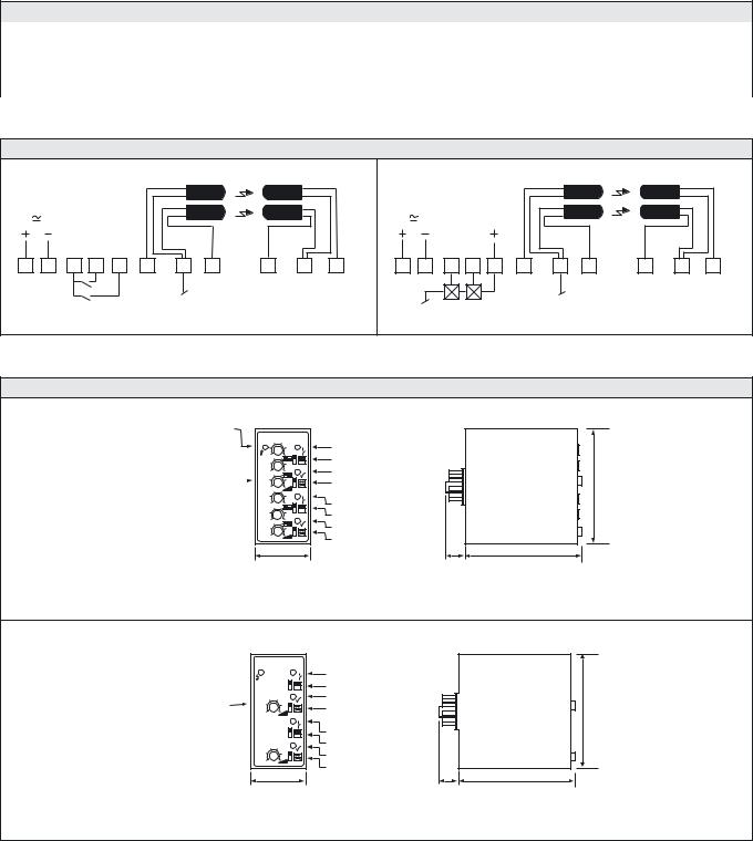
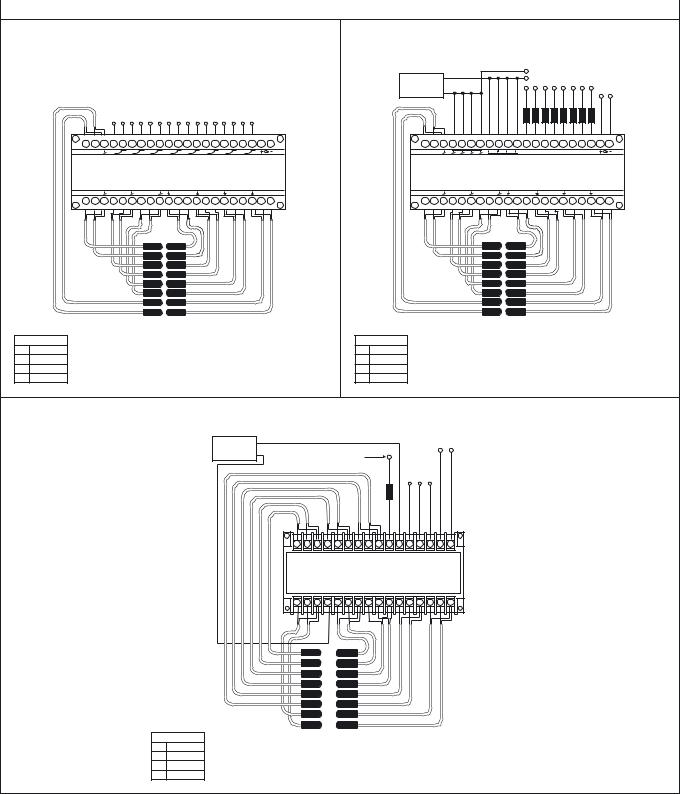
Wiring Diagrams
|
|
|
|
|
|
|
LT1 |
|
LR1 |
|
|
|
|
|
|
|
|
LT1 |
|
LR1 |
|
|
|
|
|
|
|
|
LT2 |
|
LR2 |
|
|
|
|
|
|
|
|
LT2 |
|
LR2 |
|
|
|
|
Relay |
Red |
Black |
Red |
Yellow |
Shield |
Yellow |
|
|
NPN/PNP |
|
Red |
Black |
Red |
Yellow |
Shield |
Yellow |
||
|
|
|
|
|
|
|
|
|
|
|
|
|
|
|
|
|
|
||||
|
|
|
Ch1 |
Ch2 |
|
|
|
|
|
|
|
|
Ch1 |
Ch2 |
|
|
|
|
|
|
|
2 |
10 |
1 |
3 |
4 |
5 |
7 |
11 |
9 |
8 |
6 |
2 |
10 |
3 |
4 |
1 |
5 |
7 |
11 |
9 |
8 |
6 |
|
|
|
|
|
|
Relay output |
|
|
|
|
|
|
|
|
|
Transistor output |
|
|
|
||
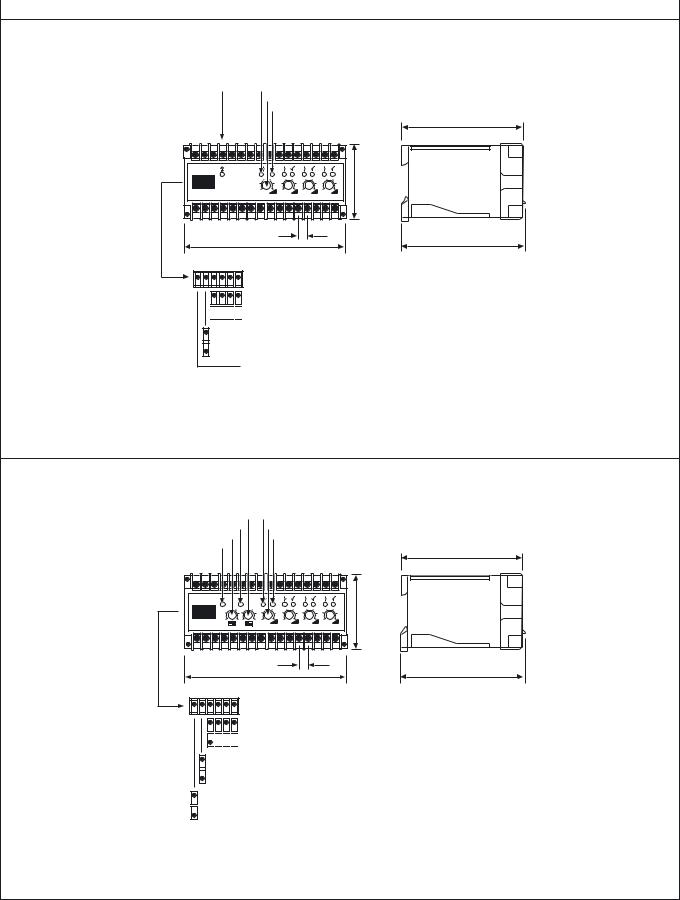
Dimensions and Descriptions
Power on indicator
CHANNEL 1
Off delay adjustment  On delay adjustment
Sensitivity adjustment 
CHANNEL 2
Off delay adjustment  On delay adjustment
  Sensitivity adjustment
35 |
CHANNEL 1
Output indicator
Light/dark switch
Signal status indicator
Long/short switch
CHANNEL 2
Output indicator
Light/dark switch
Signal status indicator
Long/short switch
13 |
78 |
76
MPA 21 A
(Units in mm)
Power on indicator 
CHANNEL 1
Sensitivity adjustment
CHANNEL 2
Sensitivity adjustment 
35 |
CHANNEL 1
Output indicator
Light/dark switch
Signal status indicator
Long/short switch
CHANNEL 2
Output indicator
Light/dark switch
Signal status indicator
Long/short switch
13 |
78 |
76
MPA 21 B
(Units in mm)
Telco reserves the right to change specifications without notice.
36 I REMOTE PHOTOELECTRIC SYSTEMS
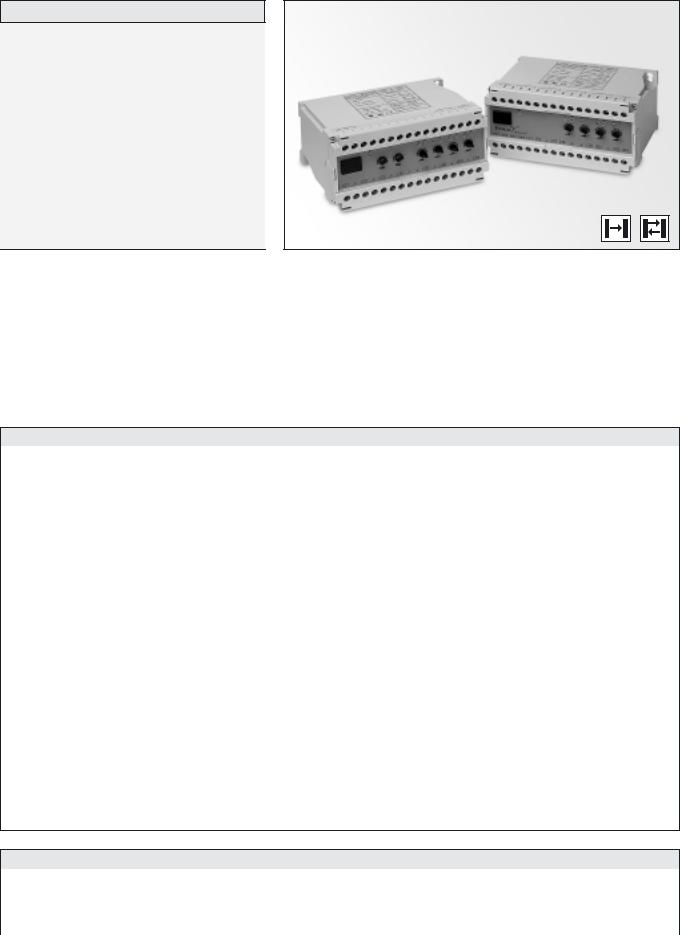
MULTIPLEXED AMPLIFIER SERIES |
MPA 41 |
|
|
Description
Operation mode and max sensing range:
Thru beam: 0-35 m Diffuse proximity: 0-2 m
230 V ac, 115 V ac, 24 V ac or 24 V dc supply voltage
Manual sensitivity adjustment
Adjustable on/off time delay
4 relays and/or 4 transistor individual outputs
1 relay and 1 transistor common output
Switch selectable light or dark function
Switch selectable long or short range
Power, output and signal level indicators
Screw terminals connection
The MPA 41 is a 4-channel, multiplexed photoelectric amplifier, which is to be used in conjunction with 4 sets of remote transmitters LT and receivers LR, from the series 100, 110 and 120.
The 4 channels operate independently of each other with their own set of remote transmitter and receiver. The multiplexing function ensures that optical cross talk between channels is prevented. The series offers a choice between 4 individual relays and/or 4 individual NPN/PNP
transistor outputs, or 1 common relay and 1 common transistor output which features an adjustable 0-10 sec on/off time delay.
This amplifier series offers manual sensitivity adjustment for each individual channel via integral potentiometers located on the front panel of the amplifier. Light or dark function and long or short range are switch selectable for each individual channel.
Technical Data
|
|
|
MPA 41 A |
|
MPA 41 B |
|
MPA 41 C |
|
MPA 41 D |
|
|
|
|
|
|
|
|
|
|
Supply voltage |
|
|
|
|
24 V dc, 24 V ac, 115 V ac or 230 V ac |
|
|
||
|
|
|
|
|
|
|
|
|
|
Voltage tolerance |
|
|
|
|
+/– 15 % |
|
|
|
|
|
|
|
|
|
|
|
|
|
|
Current consumption |
|
|
|
|
Max. 6,5 VA |
|
|
|
|
|
|
|
|
|
|
|
|
||
Output |
Relay |
|
|
1 open / 1 close, 250 V ac / 3 A, 120 V ac / 5 A |
|||||
|
|
|
|
|
|
|
|
|
|
Transistor |
|
|
|
40 mA / 30 V dc |
|
|
|
||
|
|
|
|
|
|
||||
|
|
|
|
|
|
|
|
|
|
Power on indicator |
|
|
|
|
Green LED |
|
|
|
|
|
|
|
|
|
|
|
|
|
|
Output indicator |
|
|
|
|
Red LED |
|
|
|
|
|
|
|
|
|
|
|
|
|
|
Signal level indicator |
|
|
|
|
Green LED |
|
|
|
|
|
|
|
|
|
|
|
|
|
|
LR sensor failure indicator |
|
|
|
|
– |
|
|
|
|
|
|
|
|
|
|
|
|
|
|
LT sensor failure indicator |
|
|
|
|
– |
|
|
|
|
|
|
|
|
|
|
|
|
|
|
Sensor monitor LED drive |
|
|
|
|
– |
|
|
|
|
|
|
|
|
|
|
|
|
|
|
Hysteresis |
|
|
|
|
Approx. 35 % |
|
|
|
|
|
|
|
|
|
|
|
|
|
|
|
Short range |
|
14 Hz |
|
|
25 Hz |
|||
|
Relay |
|
|
|
|
|
|
|
|
|
|
8 Hz |
|
|
17 Hz |
||||
Operation frequency |
Long range |
|
|
|
|||||
|
|
|
|
|
|
|
|
|
|
Short range |
|
|
20 Hz |
|
|
50 Hz |
|||
|
|
|
|
||||||
|
Transistor |
|
|
|
|
|
|
|
|
|
|
10 Hz |
|
|
25 Hz |
||||
|
Long range |
|
|
|
|||||
|
|
|
|
|
|
|
|
|
|
|
Short range |
|
35 ms / 35 ms |
|
|
20 ms / 20 ms |
|||
|
Relay |
|
|
|
|
|
|
|
|
|
|
|
|
|
|
|
|
||
Response time tON / tOFF |
Long range |
|
60 ms / 60 ms |
|
|
30 ms / 30 ms |
|||
|
|
|
|
|
|
|
|
|
|
Short range |
|
|
25 ms / 25 ms |
|
|
10 ms / 10 ms |
|||
|
|
|
|
||||||
|
Transistor |
|
|
|
|
|
|
|
|
|
|
|
|
|
|
|
|
||
|
Long range |
|
50 ms / 50 ms |
|
|
20 ms / 20 ms |
|||
|
|
|
|
|
|
|
|
|
|
Delay tON / tOFF |
|
|
– |
|
0 –10 sec, adjustable |
|
– |
|
0 –10 sec, adjustable |
Housing material |
|
|
|
|
Noryl |
|
|
|
|
|
|
|
|
|
|
|
|
|
|
Environmental Data
Temperature, operation |
– 10 to +50 ºC |
|
|
Temperature, storage |
– 40 to +80 ºC |
|
|
Sealing class |
IP 30 |
|
|
Approvals |
a b d |
|
|
REMOTE PHOTOELECTRIC SYSTEMS I 37
MPA 41 |
|
|
|
MULTIPLEXED AMPLIFIER SERIES |
||
|
|
|
|
|
|
|
|
|
|
|
|
|
|
Available Types |
|
|
|
|
|
|
Model |
Connection |
Supply Voltage |
24 V dc |
24 V ac |
115 V ac |
230 V ac |
|
|
|
|
|
||
Output |
|
Order Reference |
|
|||
|
|
|
|
|||
|
|
|
|
|
|
|
|
|
4 individual NPN/PNP |
MPA 41 A 603 |
MPA 41 A 602 |
MPA 41 A 601 |
MPA 41 A 600 |
MPA 41 A |
|
|
|
|
|
|
|
4 individual relays and |
MPA 41 A 703 |
MPA 41 A 702 |
MPA 41 A 701 |
MPA 41 A 700 |
|
|
|
4 individual NPN/PNP |
||||
|
|
|
|
|
|
|
|
|
|
|
|
|
|
MPA 41 B |
|
1 common relay and |
MPA 41 B 703 |
MPA 41 B 702 |
MPA 41 B 701 |
MPA 41 B 700 |
On/Off delay |
|
1 common NPN/PNP |
||||
Screw terminals |
|
|
|
|
||
|
|
|
|
|
|
|
|
|
4 individual NPN/PNP |
MPA 41 C 603 |
MPA 41 C 602 |
MPA 41 C 601 |
MPA 41 C 600 |
MPA 41 C |
|
|
|
|
|
|
|
4 individual relays and |
MPA 41 C 703 |
MPA 41 C 702 |
MPA 41 C 701 |
MPA 41 C 700 |
|
|
|
4 individual NPN/PNP |
||||
|
|
|
|
|
|
|
|
|
|
|
|
|
|
MPA 41 D |
|
1 common relay and |
MPA 41 D 703 |
MPA 41 D 702 |
MPA 41 D 701 |
MPA 41 D 700 |
On/Off delay |
|
1 common NPN/PNP |
||||
|
|
|
|
|
||
|
|
|
|
|
|
|
Note: Remote sensors to be ordered separately.
Applicable Remote Sensors and Ranges
Series |
|
|
Thru Beam |
|
|
|
|
|
Diffuse Proximity |
||
Short range |
|
|
Long range |
|
|
|
Short range |
Long range |
|||
|
|
|
|
|
|
||||||
MPA 41 A/B |
|
|
|
|
|
|
|
|
|
|
|
100 |
4 m |
|
|
|
|
8 m |
|
|
|
0,4 m |
0,6 m |
110 |
9 m |
|
|
|
|
18 m |
|
|
|
0,7 m |
1,3 m |
120 |
18 m |
|
|
|
|
35 m |
|
|
|
1,3 m |
2 m |
MPA 41 C/D |
|
|
|
|
|
|
|
|
|
|
|
100 |
2 m |
|
|
|
|
4 m |
|
|
|
0,2 m |
0,4 m |
110 |
5 m |
|
|
|
|
9 m |
|
|
|
0,4 m |
0,7 m |
120 |
9 m |
|
|
|
|
18 m |
|
|
|
0,7 m |
1,3 m |
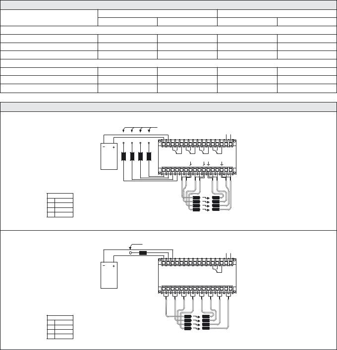
Wiring Diagrams |
|
|
|
|
|
|
|
|
|
|
|
|
|
|
|
|
Connect loads to + for NPN output or |
|
|
Power |
|
||
|
|
|
|
|
Connect loads to - for PNP output |
|
|
|
|
||
|
|
|
|
|
|
|
|
Supply |
|
||
|
|
|
|
|
|
|
|
|
|
|
|
|
|
|
|
|
+ – |
|
|
|
|
|
|
|
|
|
|
|
P/N |
|
|
|
|
|
|
|
Load |
|
|
|
CH1 |
CH2 |
CH3 |
CH4 |
|
|
|
|
Supply |
|
|
|
|
|
|
|
|
|
|
|
Load |
Load |
Load |
Load |
CH1CH2 CH3CH4 |
|
|
|
|
|
|
|
CH4 |
CH3 |
CH2 |
CH1 |
P/N P/N P/N P/N |
|
|
|
|
|
|
|
|
|
|
|
R R BI R R BI |
|
S Y Y |
S Y Y |
|
||
Wire Code |
|
|
|
|
LT1 |
|
|
LR1 |
|
|
|
R |
Red |
|
|
|
|
|
|
|
|
||
|
|
|
|
LT2 |
|
|
LR2 |
|
|
||
Bl |
Black |
|
|
|
|
LT3 |
|
|
LR3 |
|
|
Y |
Yellow |
|
|
|
|
LT4 |
|
|
LR4 |
|
|
S |
Shield |
|
|
|
MPA 41 A/C |
|
|
|
|
|
|
|
|
|
|
|
|
|
|
|
|
|
|
|
|
|
Connect load to + for NPN output or |
|
|
|
|
|
|||
|
|
|
Connect load to - for PNP output |
|
|
|
Power |
|
|||
|
|
|
|
|
|
|
|
|
|
Supply |
|
|
|
|
Load |
|
|
|
|
|
|
|
|
|
|
|
|
|
+ P/N - |
|
|
|
|
|
|
|
Load |
|
|
|
|
|
|
|
|
|
|
|
Supply |
|
|
|
|
|
|
|
|
|
|
|
|
|
|
|
R BI R BI R BI R BI S Y |
S Y |
S Y |
S Y |
|
||
Wire Code |
|
|
|
|
LT1 |
|
LR1 |
|
|
|
|
|
|
|
|
LT2 |
|
LR2 |
|
|
|
||
R |
Red |
|
|
|
|
|
|
|
|
||
|
|
|
|
LT3 |
|
LR3 |
|
|
|
||
Bl |
Black |
|
|
|
|
|
|
|
|
||
|
|
|
|
LT4 |
|
LR4 |
|
|
|
||
|
|
|
|
|
|
|
|
|
|
||
Y |
Yellow |
|
|
|
|
|
|
|
|
|
|
S |
Shield |
|
|
|
MPA 41 B/D |
|
|
|
|
|
|
|
|
|
|
|
|
|
|
|
|
|
|
38 I REMOTE PHOTOELECTRIC SYSTEMS
MULTIPLEXED AMPLIFIER SERIES |
MPA 41 |
|
|
|
|
|
|
|
Dimensions and Descriptions |
|
|
|
|
|
Power on indicator |
Output indicator channel 1 |
|||
|
Sensitivity adjustment channel 1 |
|||
|
Signal status indicator channel 1 |
|||
|
|
|
|
73 |
|
1 |
2 |
3 |
4 |
8,6
150
Dark operated


 Light operated 1 2 3 4 Channel
Long range
Short range
This switch is not in use
MPA 41 A/C
112
114
(Units in mm)
Common off delay |
Output indicator channel 1 |
|||
Common output indicator |
Sensitivity adjustment channel 1 |
|||
Common on delay |
Signal status indicator channel 1 |
|||
Common power on indicator |
|
|
|
112 |
|
|
|
|
73 |
|
1 |
2 |
3 |
4 |
|
|
|
8,6 |
|
|
150 |
|
|
114 |
Dark operated


 Light operated 1 2 3 4 Channel
Long range
Short range
Common output standard
Common output inverted
MPA 41 B/D
(Units in mm)
Telco reserves the right to change specifications without notice.
REMOTE PHOTOELECTRIC SYSTEMS I 39
MULTIPLEXED AMPLIFIER SERIES |
MPA 81 |
|
|
Description
Operation mode and max sensing range:
Thru beam: 0-35 m Diffuse proximity: 0-2 m
230 V ac, 115 V ac, 24 V ac or 24 V dc supply voltage
Manual sensitivity adjustment
Adjustable on/off time delay
8 relays or 8 transistor individual outputs
1 relay and 1 transistor common output
Switch selectable light or dark function
Switch selectable long or short range
Power, output and signal level indicators
Screw terminals connection
The MPA 81 is an 8-channel, multiplexed photoelectric amplifier, which is to be used in conjunction with 8 sets of remote transmitters LT and receivers LR, from the series 100, 110 and 120.
The 8 channels operate independently of each other with their own set of remote transmitter and receiver. The multiplexing function ensures that optical cross talk between channels is prevented. The series offers a choice between 8 individual relays or 8 individual NPN/PNP transistor
outputs, or 1 common relay and 1 common NPN/PNP transistor output which has an adjustable 0-10 sec on-off time delay.
This amplifier series offers manual sensitivity adjustment for each individual channel, via integral potentiometers located on the front panel of the amplifier. Light or dark function and long or short range are switch selectable for each individual channel.
Technical Data
|
|
|
MPA 81 A |
|
MPA 81 B |
|
MPA 81 C |
|
MPA 81 D |
|
|
|
|
|
|
|
|
|
|
Supply voltage |
|
|
|
|
24 V dc, 24 V ac, 115 V ac or 230 V ac |
|
|
||
|
|
|
|
|
|
|
|
|
|
Voltage tolerance |
|
|
|
|
+/– 15 % |
|
|
|
|
|
|
|
|
|
|
|
|
|
|
Current consumption |
|
|
|
|
Max. 6,5 VA |
|
|
|
|
|
|
|
|
|
|
|
|
||
Output |
Relay |
|
|
1 open / 1 close, 250 V ac / 3 A, 120 V ac / 5 A |
|||||
|
|
|
|
|
|
|
|
|
|
Transistor |
|
|
|
40 mA / 30 V dc |
|
|
|
||
|
|
|
|
|
|
||||
|
|
|
|
|
|
|
|
|
|
Power on indicator |
|
|
|
|
Green LED |
|
|
|
|
|
|
|
|
|
|
|
|
|
|
Output indicator |
|
|
|
|
Red LED |
|
|
|
|
|
|
|
|
|
|
|
|
|
|
Signal level indicator |
|
|
|
|
Green LED |
|
|
|
|
|
|
|
|
|
|
|
|
|
|
LR sensor failure indicator |
|
|
|
|
– |
|
|
|
|
|
|
|
|
|
|
|
|
|
|
LT sensor failure indicator |
|
|
|
|
– |
|
|
|
|
|
|
|
|
|
|
|
|
|
|
Sensor monitor LED drive |
|
|
|
|
– |
|
|
|
|
|
|
|
|
|
|
|
|
|
|
Hysteresis |
|
|
|
|
Approx. 35 % |
|
|
|
|
|
|
|
|
|
|
|
|
|
|
|
Short range |
|
|
9 Hz |
|
|
18 Hz |
||
|
Relay |
|
|
|
|
|
|
|
|
|
|
5 Hz |
|
|
11 Hz |
||||
Operation frequency |
Long range |
|
|
|
|||||
|
|
|
|
|
|
|
|
|
|
Short range |
|
|
11 Hz |
|
|
28 Hz |
|||
|
|
|
|
||||||
|
Transistor |
|
|
|
|
|
|
|
|
|
|
6 Hz |
|
|
14 Hz |
||||
|
Long range |
|
|
|
|||||
|
|
|
|
|
|
|
|
|
|
|
Short range |
|
55 ms / 55 ms |
|
|
28 ms / 28 ms |
|||
|
Relay |
|
|
|
|
|
|
|
|
|
|
|
|
|
|
|
|
||
Response time tON / tOFF |
Long range |
|
100 ms / 100 ms |
|
|
46 ms / 46 ms |
|||
|
|
|
|
|
|
|
|
|
|
Short range |
|
|
45 ms / 45 ms |
|
|
18 ms / 18 ms |
|||
|
|
|
|
||||||
|
Transistor |
|
|
|
|
|
|
|
|
|
|
|
|
|
|
|
|
||
|
Long range |
|
90 ms / 90 ms |
|
|
36 ms / 36 ms |
|||
|
|
|
|
|
|
|
|
|
|
Delay tON / tOFF |
|
|
– |
|
0 –10 sec, adjustable |
|
– |
|
0 –10 sec, adjustable |
Housing material |
|
|
|
|
Noryl |
|
|
|
|
|
|
|
|
|
|
|
|
|
|
Environmental Data
Temperature, operation |
– 10 to +50 ºC |
|
|
Temperature, storage |
– 40 to +80 ºC |
|
|
Sealing class |
IP 30 |
|
|
Approvals |
a b d |
|
|
REMOTE PHOTOELECTRIC SYSTEMS I 41

MPA 81 |
|
|
|
MULTIPLEXED AMPLIFIER SERIES |
||
|
|
|
|
|
|
|
|
|
|
|
|
|
|
Available Types |
|
|
|
|
|
|
Model |
Connection |
Supply Voltage |
24 V dc |
24 V ac |
115 V ac |
230 V ac |
|
|
|
|
|
||
Output |
|
Order Reference |
|
|||
|
|
|
|
|||
|
|
|
|
|
|
|
MPA 81 A |
|
8 individual relays |
MPA 81 A 503 |
MPA 81 A 502 |
MPA 81 A 501 |
MPA 81 A 500 |
|
|
|
|
|
|
|
|
8 individual NPN/PNP |
MPA 81 A 603 |
MPA 81 A 602 |
MPA 81 A 601 |
MPA 81 A 600 |
|
|
|
|||||
|
|
|
|
|
|
|
MPA 81 B |
|
1 common relay and |
MPA 81 B 703 |
MPA 81 B 702 |
MPA 81 B 701 |
MPA 81 B 700 |
On/Off delay |
|
1 common NPN/PNP |
||||
Screw terminals |
|
|
|
|
||
|
|
|
|
|
|
|
MPA 81 C |
|
8 individual relays |
MPA 81 C 503 |
MPA 81 C 502 |
MPA 81 C 501 |
MPA 81 C 500 |
|
|
|
|
|
|
|
|
8 individual NPN/PNP |
MPA 81 C 603 |
MPA 81 C 602 |
MPA 81 C 601 |
MPA 81 C 600 |
|
|
|
|||||
|
|
|
|
|
|
|
MPA 81 D |
|
1 common relay and |
MPA 81 D 703 |
MPA 81 D 702 |
MPA 81 D 701 |
MPA 81 D 700 |
On/Off delay |
|
1 common NPN/PNP |
||||
|
|
|
|
|
||
|
|
|
|
|
|
|
Note: Remote sensors to be ordered separately.
Applicable Remote Sensors and Ranges
Series |
|
Thru Beam |
|
Diffuse Proximity |
||
|
|
|
|
|
|
|
Short range |
|
Long range |
Short range |
|
Long range |
|
|
|
|
||||
|
|
|
|
|
|
|
MPA 81 A/B |
|
|
|
|
|
|
|
|
|
|
|
|
|
100 |
4 m |
|
8 m |
0,4 m |
|
0,6 m |
|
|
|
|
|
|
|
110 |
9 m |
|
18 m |
0,7 m |
|
1,3 m |
|
|
|
|
|
|
|
120 |
18 m |
|
35 m |
1,3 m |
|
2 m |
|
|
|
|
|
|
|
MPA 81 C/D |
|
|
|
|
|
|
|
|
|
|
|
|
|
100 |
2 m |
|
4 m |
0,2 m |
|
0,4 m |
|
|
|
|
|
|
|
110 |
5 m |
|
9 m |
0,4 m |
|
0,7 m |
|
|
|
|
|
|
|
120 |
9 m |
|
18 m |
0,7 m |
|
1,3 m |
|
|
|
|
|
|
|
42 I REMOTE PHOTOELECTRIC SYSTEMS
MULTIPLEXED AMPLIFIER SERIES |
MPA 81 |
|
|
|
|
|
|
|
Wiring Diagrams |
|
|
|
|
|
|
|
|
CH1 |
CH2 |
CH3 |
CH4 |
CH5 |
CH6 |
|
CH7 CH8 |
|
|
|
|
|
C NC C NC C NC C NC C NC C NC C NC C NC |
|
|
|||||||
|
R |
R |
BI |
|
|
|
|
|
|
|
|
|
|
LT7 |
LT8 |
1 |
2 |
3 |
4 |
5 |
6 |
7 |
8 |
|
|
|
LT1 |
LT2 |
LT3 LT4 |
LT5 |
LT6 |
LR1 LR2 |
LR3 LR4 |
|
LR5 LR6 |
LR7 LR8 |
|
|
|
R R |
R R |
R R |
BI |
Y Y |
Y Y |
|
Y Y |
Y Y |
|
||
|
|
BI |
BI |
|
S |
|
S |
|
S |
S |
|
|
|
|
|
|
|
LT1 |
LR1 |
|
|
|
|
|
|
|
|
|
|
|
LT2 |
LR2 |
|
|
|
|
|
|
|
|
|
|
|
LT3 |
LR3 |
|
|
|
|
|
|
|
|
|
|
|
LT4 |
LR4 |
|
|
|
|
|
|
|
|
|
|
|
LT5 |
LR5 |
|
|
|
|
|
|
|
|
|
|
|
LT6 |
LR6 |
|
|
|
|
|
|
|
|
|
|
|
LT7 |
LR7 |
|
|
|
|
|
|
|
|
|
|
|
LT8 |
LR8 |
|
|
|
|
|
|
Wire Code |
|
|
|
|
|
|
|
|
|
Wire Code |
||
R |
Red |
|
|
|
|
|
|
|
|
|
R |
Red |
Bl |
Black |
|
MPA 81 A/C 50x (Relay Output) |
Bl |
Black |
|||||||
Y |
Yellow |
|
Y |
Yellow |
||||||||
|
|
|
|
|
|
|
|
|
||||
S |
Shield |
|
|
|
|
|
|
|
|
|
S |
Shield |
|
|
|
|
|
Connect Loads to - for PNP output or |
||
|
+ |
|
|
|
Connect Loads to + for NPN output |
||
|
|
|
|
|
|
|
|
Load supply |
|
|
|
|
|
Power supply |
|
|
- |
|
|
|
|
|
|
|
|
|
|
|
|
|
|
R |
R |
BI |
|
|
|
|
|
LT7 |
LT8 |
|
|
1 |
2 3 4 5 |
6 7 |
8 |
LT1 |
LT2 |
LT3 LT4 |
LT5 LT6 |
LR1 LR2 |
LR3 LR4 |
LR5 LR6 |
LR7 LR8 |
R R |
R R |
R R |
Y Y |
Y Y |
Y Y |
Y Y |
|
|
BI |
BI |
BI |
S |
S |
S |
S |
LT1 LR1
LT2 LR2
LT3 LR3
LT4 LR4
LT5 LR5
LT6 LR6
LT7 LR7
LT8 LR8
MPA 81 A/C 60x (Transistor Output)
+ |
|
|
|
|
|
|
Power supply |
Load supply |
Connect load to + for NPN output or |
|
|||||
- |
Relay |
||||||
|
Connect load to - for PNP output |
|
|||||
|
|
|
|
|
|
|
output |
|
|
|
|
|
|
|
C NO NC |
|
|
|
|
|
|
|
Load |
|
R R |
BI |
R R |
BI |
R |
R |
BI |
|
|
|
|
||||
|
|
|
S |
|
R R BI |
Y Y S |
Y Y |
Y Y S |
Y Y S |
|
LT1 |
LR1 |
|
|
LT2 |
LR2 |
|
|
LT3 |
LR3 |
|
|
LT4 |
LR4 |
|
|
LT5 |
LR5 |
|
|
LT6 |
LR6 |
|
|
LT7 |
LR7 |
|
|
LT8 |
LR8 |
|
Wire Code |
|
||
R |
Red |
|
|
Bl |
Black |
MPA 81 B/D |
|
Y |
Yellow |
||
|
|||
S Shield
REMOTE PHOTOELECTRIC SYSTEMS I 43

MULTIPLEXED AMPLIFIER SERIES |
MPA 81 |
|
|
|
|
|
|
|
Dimensions and Descriptions |
|
|
|
|
|
Output indicator channel 1 |
|
|
|
||||
Sensitivity adjustment channel 1 |
|
|
|||||
Power on indicator |
Signal status indicator channel 1 |
|
|||||
1 |
2 |
3 |
4 |
5 |
6 |
7 |
8 |
|
73 |
|
8,6 |
200 |
118 |
|
|
|
|
|
|
|
Dark operated |
|
|
|
|
|
|
|
Light operated |
1 |
2 |
3 |
4 5 |
6 |
7 |
8 |
Channel |
|
|
|
|
|
|
|
Long range |
|
|
|
|
|
|
|
Short range |
|
|
|
|
|
|
|
This switch is not in use |
MPA 81 A/C
(Units in mm)
Common off delay |
Output indicator channel 1 |
|||||||||||||
Common output indicator |
Sensitivity adjustment channel 1 |
|||||||||||||
Common on delay |
Signal status indicator channel 1 |
|||||||||||||
Common power on indicator |
112 |
|
|
|||||||||||
|
|
|
|
|
|
|
|
|
|
|
|
|
|
|
|
|
|
|
|
|
|
|
|
|
|
|
|
|
|
|
|
|
|
|
|
|
|
|
|
|
|
|
|
|
73 |
|
|
8,6 |
|
|
150 |
114 |
|
CH1 |
|
|
|
CH2 |
|
|
|
CH3 |
|
|
|
CH4 |
Dark operated |
Light operated |
|
CH5 |
|||
|
|
||
CH6 |
|
|
|
CH7 |
|
|
|
CH8 |
Long range |
|
|
COM |
Short range |
||
COM |
Output std. |
Output inverted |
MPA 81 B/D
(Units in mm)
Telco reserves the right to change specifications without notice.
44 I REMOTE PHOTOELECTRIC SYSTEMS