

Газовые турбины GE
.pdfGE
Oil & Gas
Gas Turbines

Contents
3 |
|
|
Introduction |
|||
|
|
|
GE5 |
|
||
4 |
|
|||||
|
|
|
GE10 |
|
||
8 |
|
|||||
|
|
|
MS5001 |
|||
10 |
||||||
|
|
|
MS5002C-D |
|||
11 |
||||||
|
|
|
MS5002E |
|||
12 |
|
|||||
|
|
|
MS6001B/MS7001EA/MS9001E |
|||
13 |
|
|||||
|
|
|
PGT16 |
|||
14 |
|
|||||
|
|
|
PGT25 |
|||
15 |
|
|||||
|
|
|
PGT25+ |
|||
16 |
|
|||||
|
|
|
LM6000 |
|||
17 |
|
|||||
|
|
|
Main Components |
|||
18 |
|
|||||
|
|
|
|
Axial Compressor |
||
|
|
|
18 |
|
||
|
|
|
|
First Stage Nozzles |
||
|
|
|
19 |
|
||
|
|
|
|
Buckets and Wheels |
||
|
|
|
19 |
|
||
|
|
|
Gas Turbine Operability |
|||
20 |
|
|
||||
|
|
|
LNG, Exploration and Production, |
|||
22 |
|
|
||||
|
|
|
Floating Production Units |
|||
|
|
|
Pipeline Transportation |
|||
23 |
|
|
||||
|
|
|
Refinery and Petrochemicals |
|||
24 |
|
|
||||
|
|
|
Test Facilities |
|||
25 |
|
|
||||
|
|
|
Service |
|||
26 |
|
|
||||
|
|
|
Training |
|||
27 |
|
|
||||
|
|
|
Gas Turbine Data Sheet |
|||
28 |
|
|
||||
2 GE Gas Turbines

GE manufactures a complete line of gas turbines for all major Oil & Gas Industry applications. They are installed in natural gas plants, gas compression stations, oil booster stations, petrochemical plants and power generation and cogeneration plants worldwide. GE’s Oil & Gas business has long-standing experience in manufacturing gas turbines dating back to 1961 when a manufacturing agreement was established with GE (U.S.A.) to complement the existing portfolio of products for the petroleum and petrochemical industries (reciprocating and centrifugal compressors, gas engines, pumps, valves, etc.). A proven combination of sound design and quality assurance techniques places these gas turbines among the world’s most reliable. Basic models produced by GE cover the 5,000 to 124,000 kW power range. They can be provided in simple or regenerative cycles for mechanical drive or generator drive applications. Extensive research and development, advanced design procedures, modern manufacturing technology and on-site experience are behind the success achieved by GE gas turbines.
3 GE Gas Turbines

GE5 Gas Turbines
The new GE5 is a compact, state-of-the-art, 6 MW class industrial gas turbine. The unit was developed in two configurations: a cold-end drive single shaft for power generation and a hotend drive twin shaft for mechanical drive applications. Maximum commonality has been maintained between the single and twin shaft models. Both units share a common gas generator, with operating and maintenance benefits in installations where mixed operation is required. The twin shaft engine is obtained by simply removing the second stage turbine from the single shaft unit and adding a two-stage power turbine.
The unit is an evolution of the existing PGT5 which builds on the experience of the successful GE10 model. The merging of proven GE’s Aircraft Engine and Oil & Gas technology coupled with the benefits of GE’s Six Sigma Total Quality Methodology have resulted in a rugged machine with high efficiency and reliability, and low operating and maintenance cost.
The high efficiency of the machine coupled with low emissions make the GE5 a leader in its class for most applications.
While the single shaft version is particularly suitable for power generation and cogeneration due to the high exhaust temperature, the twin shaft version, with wide operating speed range, is designed to be a reliable and efficient mechanical drive for compressors and pumps.
COMPRESSOR
The GE5 compressor benefits from several decades of compressor design evolution focused on achieving higher efficiency. The new compressor is scaled from the similar GE10 unit. It is a high performance, axial flow design derived from GE Aircraft Engine technology. Utilizing GE Aircraft Engine expertise, we have greatly improved overall compressor performance without sacrificing reliability or mechanical integrity.
The 11-stage compressor produces a pressure ratio of 14.8:1. The first three stages of stator blades are adjustable to optimize efficiency by maximizing exhaust gas temperature at part load operation. Compressor blades are assembled onto a solid forged rotor while stator blades are mounted onto ductile cast iron casings.
TURBINE
The HP turbine itself is a compact, high efficiency design with two stages in the single shaft version and three stages in the twin shaft model (2 in the LPT Turbine). The advanced design methodology used resulted in a high performance machine with significantly fewer parts. In addition, state-of-the-art cooling techniques permitted the use of well proven materials.
The GE5 uses an enhanced nozzle and bucket design similar to those used in aircraft engines. Cooling air is provided to the first stage nozzles and buckets to enable higher firing temperatures and enhanced efficiency.
The LP turbine of the twin shaft version has two stages
4 GE Gas Turbines
and has been designed exploiting the experience the company has gained over the past 20 years with the PGT25, PGT10, PGT16 and more recently with the PGT25+ (High Speed Power Turbine). The design speed of the GE5-2 low pressure turbine is 12,500 rpm, with a capability range from 50% to 105%, which is ideal for direct coupling of our centrifugal compressors in the 6 MW power range.
COMBUSTOR
The GE5 uses an annular combustor architecture, to achieve the maximum efficiency while maintaining the highest reliability standards. The unit is configured with a DLE combustion system that reduces the NOx and CO emission levels. It consists of a compact annular combustor in Hastelloy X with 18 fuel nozzles. Each fuel nozzle includes a double counter-rotating swirler to optimize fuel mixing and flame stability for extra clean combustion.
This combustion system is designed for operation on natural gas. One fixed, high-energy spark ignitor is used to achieve simple and reliable ignition.
GE5-1 Gas Turbine
5 GE Gas Turbines

GE5 Gas Turbines
PACKAGE
The gas turbine packages were designed with an emphasis on standardization, and optimization of factory and field assembly operations. The result is a standard package capable of satisfying the needs of a typical user for low installation and maintenance costs. The package is also designed and manufactured as a modular system. Both the single and twin shaft gas turbines are normally supplied as completely enclosed, on-base soundproof packages of very compact dimensions with standard noise attenuation levels of 85 dB(A) at 1 m. The Starting System, Lube Oil System and Fuel System are fully integrated on the base plate.
In the single shaft configuration, the base plate also supports the load gear; the off-base equipment is limited to the lube oil cooler and the generator. The entire GE5-1 package is compact, with a footprint of only 5810 mm (L) x 2500 mm (W) providing the user with the flexibility to locate the system indoors or near preexisting facilities. The inlet filtration module and inlet duct are designed to be perfectly integrated with the enclosure and, in order to optimize the footprint and transportation, are supported by the enclosure itself. For the twin shaft, the design guideline has been the flexibility to satisfy a broad spectrum of customer plant needs. As required by the Oil & Gas Industry, the standard enclosure was designed to be equipped with different filtration systems (conventional/self cleaning), different inlet/exhaust duct arrangements and noise levels and always allowing high accessibility and maintainability.
Both the single and twin shaft packages are provided with wide access doors conveniently located around the enclosure for easy access to the engine assembly and auxiliary components.
6 GE Gas Turbines
MAINTENANCE PHILOSOPHY
A fundamental philosophy of the new GE5 gas turbine is simplicity of design, layout and procedures. This affords the GE5 a position of market leadership in cost and availability through innovative programs for service and sparing, and through package assembly and disassembly flexibility. Drawing on GE’s undisputed leadership in the design and manufacture of both aero-derivative and heavy-duty machines, the GE5 represents a unique marriage of the best of both types of engines.
This provides customers with the benefit of a variety of cost-effective service programs (e.g., condition-based maintenance, site-based or exchange engine programs) and the ability to tailor the service offering to best suite the customer’s specific applications.
SOME KEY POINTS:
Annual borescope inspections are the basis of the condition based maintenance program.
The inspection of the hot parts is carried out approximately every two years. Major overhaul of the gas turbine is required at around 50,000 fired hours, and can be completed on site, or in a shop; effects of downtime can be minimized through the use of an exchange engine.
GE5-2 Gas Turbine
7 GE Gas Turbines

GE10 Gas Turbines
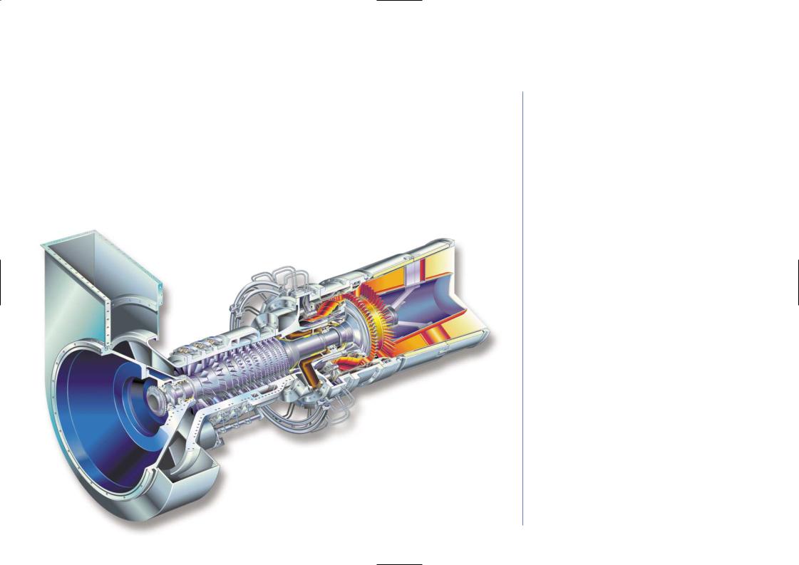
The GE10 is a 12 MW range heavy-duty gas turbine available in both single shaft and two shaft versions. It is the evolution of the field-proven PGT10A and incorporates the latest in aerodynamic design in a compact and versatile package arrangement. The design of the GE10 has been highly refined based on the extensive experience gained operating in all types of environments. There are over one hundred units running under conditions ranging from the cold of Alaska and Siberia to the heat of the desert and the humidity of the tropics.
Its efficiency and operational flexibility make the GE10 a cost-effective choice for all applications. The gas generator consists of an 11 stage, high efficiency, axial-flow compressor and a single combustion chamber capable of burning a great variety of fuels. Maximum commonality has been maintained between the single and twin shaft models. Both units use the same gas generator. The two shaft engine is obtained by simply removing the third stage turbine from the single shaft unit and adding a two-stage low pressure power turbine. This feature is particularly beneficial in reducing operating and maintenance costs in installations where mixed operation is required.
GE10-1 Gas Turbine
COMPRESSOR
The compressor is a high performance eleven stage axial flow design with a 15.5:1 pressure ratio operating under transonic flow conditions, derived from GE’s Aircraft Engine aero-derivative technology. The first three rows of stator blades are variable to optimize cycle efficiency over a wide range of loads. The gas generator is joined to the base plate at the load flange location. This configuration avoids load flange movement during all operating conditions (start-up, warm-up, full speed/full load) and during thermal transients.
TURBINE
The power turbine is available in two configurations: a single shaft version primarily for power generation; and a two shaft version for mechanical drive applications.
Generator Drive — Single Shaft Version.
The GE10-1 is a single shaft heavy duty gas turbine designed primarili for generator drive applications. The turbine section is composed of three reaction stages. The first two stages use the proven design of the previous PGT10 HP turbine model with cooling provided by air bled from the axial compressor.
The second and third stages have interlocked shrouds to limit tip leakage and blade vibration. At partial load, inlet variable guide vanes permit optimization of performance with no appreciable change from simple cycle full load efficiency.
The GE10 is a compact turbogenerator optimized for simple cycle, combined cycle and cogeneration plants (e.g., power shaft on cold side; axial discharge of hot gases) and suitable for utilization even where space is limited.
8 GE Gas Turbines

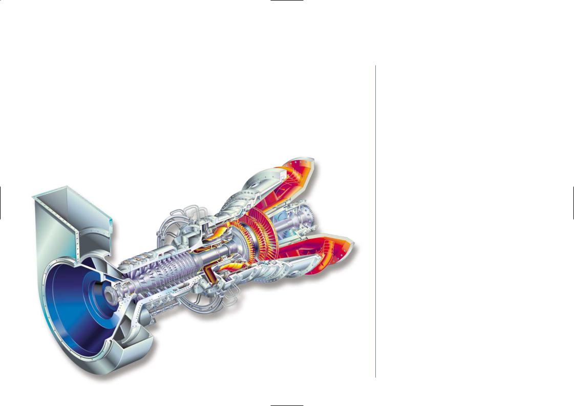
Mechanical Drive — Two Shaft Version.
The GE10-2 is the two shaft version of the GE10 intended for mechanical drive applications. The turbine consists of four reaction stages. The first two stages or High Pressure Turbine which are used to drive the axial compressor are common with the GE10-1 model. The low pressure shaft is a double stage, high-energy turbine with variable first stage nozzles which provide maximum flexibility for mechanical drive applications. These third and forth stages which make up the Low Pressure Turbine are coupled to the power shaft driving the load. They are cooled by air bled from the axial compressor.
COMBUSTOR
The combustion system consists of a single, slot-cooled combustion chamber assembly that permits quick and easy maintenance of the hot gas path. This combustion chamber is able to burn a wide range of fuels including liquid distillates, residuals and all gaseous fuels including low BTU gas with system modifications.
The GE10 combustion system is available in both conventional and DLE (dry low emissions) configurations. The DLE system is a simple, field-proven design that guarantees operation at 25 ppmv NOx (burning Natural Gas). The GE10 can also utilize steam and water injection for NOx reduction and power augmentation. Further reduction of emission levels is a constant objective of our continuing combustion development and test programs.
AUXILIARIES
The integrated lubrication system (including oil tank) that feeds the gas turbine, the speed reduction gear and the electric generator is located on the turbine base plate. The main lube oil pump is mechanically driven by the gearbox. An AC electric motor-driven pump guarantees lubrication during normal operation while a
DC electric motor-driven pump is provided for emergency backup. In the standardized package configuration the oil is cooled by an air cooler. A water cooler can be provided upon customer request.
The thrust and journal bearings are of the tilting pad type. The starting system consists of a V.F.D. motor drive for the single shaft version.
The twin shaft can be equipped with a torque converter plus electric motor or starting expansion turbine.
The GE10 control system has been implemented to assure a high degree of integration and standardization between the engine and the turbine generator package. Programmable modules guarantee easy implementation of any control and protection scheme to tailor the control system to the application and customer needs.
PACKAGE
The package designed for power generation applications is optimized to minimize plant dimensions and to reduce maintenance cost and time. In the standard configuration, the speed reduction gear is mounted on the gas turbine base plate. The auxiliaries are installed on a separate base plate permanently joined to that of the gas turbine base plate to form a single lift on which the sound-insulated enclosure is mounted.
The electric generator is installed on a concrete foundation to limit the shipping dimensions. The overall length of the genset is about 13 m.
The other modules completing the system are the oil/air exchangers, the air intake filter chamber, the suction duct (vertical suction) and the exhaust system (axial exhaust).
The enclosure has a sound pressure level lower than 85 dBA at 1 m. This acoustic design meets ISO NR 50 limits at 100 m.
9 GE Gas Turbines

MS5001 Gas Turbines
The MS5001 single shaft turbine is a compact heavy-duty prime mover designed for long life and ease of operation and maintenance. The three main features of its simple design are:
-17-stage, axial compressor
-Combustion system with 10 chambers capable of burning a wide range of fuels including natural gas, light and heavy distillates, and crude and residual oil. A DLN System is also available.
-Two-stage turbine with high energy stage design. The first-stage nozzles are cooled by the axial compressor discharge air.
The MS5001 Gas Turbine is the ideal solution for power generation where low maintenance, reliability and economy of fuel utilization are required. Low operating and investment costs make the MS5001 package power plant an economically attractive system for load generation. The MS5001 is also ideally suited for cogeneration achieving a very high fuel utilization index and considerable fuel savings. Typical applications are industrial plants for cogeneration of power and process steam or district heating systems.
As a consequence of the extremely favorable operating, maintenance and economic characteristics of the MS5001 it has been very well accepted in the industry and there are more than 2500 units in operation all over the world.
MS5001 Gas Turbine
10 GE Gas Turbines