

Tesla_ModelS_ERG
.PDF2012 - 2013
EMERGENCY RESPONSE
GUIDE
This guide is intended only for use by trained and certified rescuers and first responders. It assumes that readers have a comprehensive understanding of how safety systems work and have completed the appropriate training and certification required to safely handle rescue situations. Therefore, this guide provides only the specific information required to understand and safely handle the fully electric Model S in an emergency situation. It describes how to identify Model S, and provides the locations and descriptions of its high voltage components, airbags, inflation cylinders, seat belt pre-tensioners, and high strength materials used in its body structure. This guide includes the high voltage disabling procedure and any safety considerations specific to Model S. Failure to follow recommended practices or procedures can result in serious injury or death.
The high voltage battery is the main energy source. Model S does not have a traditional gasoline or diesel engine and therefore does not have a fuel tank.

IDENTIFYING MODEL S................................................................................... |
1 |
BADGING..................................................................................................................................... |
1 |
LARGE SCREEN..................................................................................................................... |
2 |
CHARGE PORT....................................................................................................................... |
2 |
HIGH VOLTAGE COMPONENTS .................................................................. |
3 |
OVERVIEW OF HIGH VOLTAGE COMPONENTS................................................... |
3 |
HIGH VOLTAGE BATTERY ................................................................................................ |
4 |
DC-DC CONVERTER ........................................................................................................... |
5 |
HIGH VOLTAGE CABLING................................................................................................. |
6 |
CHARGERS................................................................................................................................ |
7 |
DRIVE UNIT.............................................................................................................................. |
8 |
LOW VOLTAGE SYSTEM ................................................................................ |
9 |
12V BATTERY........................................................................................................................... |
9 |
FIRST RESPONDER CUT LOOP ................................................................ |
10 |
FIRST RESPONDER CUT LOOP.................................................................................... |
10 |
CUTTING THE FIRST RESPONDER LOOP................................................................ |
11 |
STABILIZING MODEL S................................................................................. |
12 |
AIRBAGS AND SUPPLEMENTARY RESTRAINT SYSTEM (SRS) ..... |
13 |
AIRBAGS................................................................................................................................... |
13 |
AIRBAG INFLATION CYLINDERS................................................................................. |
13 |
SEAT BELT PRE-TENSIONERS ...................................................................................... |
14 |
HIGH STENGTH STEEL ................................................................................. |
15 |
NO-CUT ZONES............................................................................................... |
16 |
RESCUE OPERATIONS ................................................................................. |
17 |
FULLY OR PARTIALLY SUBMERGED VEHICLES ................................................. |
17 |
PUSHING ON THE FLOOR PAN.................................................................................... |
17 |
FIREFIGHTING ....................................................................................................................... |
18 |
HIGH VOLTAGE BATTERY - FIRE DAMAGE ........................................................... |
18 |
LIFTING MODEL S .......................................................................................... |
19 |
OPENING MODEL S ...................................................................................... |
20 |
USING THE KEY.................................................................................................................. |
20 |
OPENING DOORS.............................................................................................................. |
20 |
OPENING REAR DOORS WITH NO POWER........................................................ |
20 |
OPENING THE TRUNK....................................................................................................... |
21 |
OPENING THE HOOD (FRONT TRUNK) .................................................................. |
21 |
HIGH VOLTAGE LABELS ............................................................................. |
22 |
INDEX ................................................................................................................. |
23 |
CONTENTS OF TABLE
P/N: SID-12-0048A REV: 1

BADGING
Model S has three main badges to distinguish it.
GUIDE RESPONSE EMERGENCY
S MODEL IDENTIFYING
1

LARGE SCREEN |
|
CHARGE PORT |
|||
Model S has a large 17” touchscreen. |
|
Model S has a charge port that is integrated into the taillight on the rear |
|||
|
|
|
driver’s side fender. |
||
Instrument panel |
Touchscreen |
||||
|
|
|
|
|
|
|
|
|
|
|
|
|
|
|
|
|
|
|
|
|
|
|
|
GUIDE RESPONSE EMERGENCY
S MODEL IDENTIFYING
2

OVERVIEW OF HIGH VOLTAGE COMPONENTS
1.Battery
2.DC-DC converter
3.High voltage cabling (colored orange)
4.10 kW on-board master charger
5.Drive unit
6.Charge port
7.OPTIONAL: 10 kW on-board slave charger
WARNING: Regardless of the disabling procedure you use, ALWAYS ASSUME THAT ALL HIGH VOLTAGE COMPONENTS ARE ENERGIZED! Cutting, crushing or touching high voltage components can result in serious injury or death.
COMPONENTS VOLTAGE HIGH GUIDE RESPONSE EMERGENCY
3

HIGH VOLTAGE BATTERY
Model S is equipped with a floor-mounted 400 volt lithium-ion high voltage battery. Never breach the high voltage battery when lifting from under the vehicle. When using rescue tools, also pay special attention to ensure that you do not breach the floor pan.
High voltage battery is located below the floor
WARNING: Regardless of the disabling procedure you use, ALWAYS ASSUME THAT ALL HIGH VOLTAGE COMPONENTS ARE ENERGIZED! Cutting, crushing or touching high voltage components can result in serious injury or death.
COMPONENTS VOLTAGE HIGH GUIDE RESPONSE EMERGENCY
4

DC-DC CONVERTER
The DC-DC converter is located in the front right wheel well, on the passenger side of the firewall. It transforms the high voltage current from the 400 volt battery to low voltage to charge the Model S 12 volt battery. High voltage is present at the DC-DC converter. Use caution when cutting in this area during a dash lift (dash roll) procedure —use work-around techniques, if necessary.
DC-DC converter is located on the passenger side, towards the front
WARNING: Regardless of the disabling procedure you use, ALWAYS ASSUME THAT ALL HIGH VOLTAGE COMPONENTS ARE ENERGIZED! Cutting, crushing or touching high voltage components can result in serious injury or death.
COMPONENTS VOLTAGE HIGH GUIDE RESPONSE EMERGENCY
5

HIGH VOLTAGE CABLING
High voltage cabling is highlighted in dark orange in the following illustration.
High voltage cabling is routed under the rear seats and inside the rocker panel on the passenger side front
WARNING: Regardless of the disabling procedure you use, ALWAYS ASSUME THAT ALL HIGH VOLTAGE COMPONENTS ARE ENERGIZED! Cutting, crushing or touching high voltage components can result in serious injury or death.
COMPONENTS VOLTAGE HIGH GUIDE RESPONSE EMERGENCY
6

CHARGERS
Model S has one (standard) or two (optional) chargers under the rear seat. These chargers convert the AC current from a charging station to DC for charging the high voltage battery. A High Voltage Junction Box, located between the chargers, routes any surplus energy from regenerative braking back to the battery.
OPTIONAL:
Slave charger (under rear driver side seat)
High Voltage
Junction Box
Master charger (under rear passenger side seat)
Charger(s) are located under the rear seat
WARNING: Regardless of the disabling procedure you use, ALWAYS ASSUME THAT ALL HIGH VOLTAGE COMPONENTS ARE ENERGIZED! Cutting, crushing or touching high voltage components can result in serious injury or death.
COMPONENTS VOLTAGE HIGH GUIDE RESPONSE EMERGENCY
7
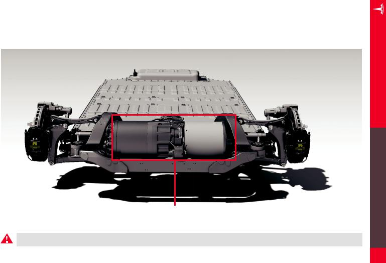
DRIVE UNIT
The drive unit is located between the rear wheels under the floor pan of the Model S. It converts the DC current from the high voltage battery into the
3-phase AC current that the electric motor uses to power the wheels.
Drive unit is located between the rear wheels
WARNING: Regardless of the disabling procedure you use, ALWAYS ASSUME THAT ALL HIGH VOLTAGE COMPONENTS ARE ENERGIZED! Cutting, crushing or touching high voltage components can result in serious injury or death.
COMPONENTS VOLTAGE HIGH GUIDE RESPONSE EMERGENCY
8