

1
Compositional Analysis of Naphtha and Reformate
Rune Prestvik
SINTEF Applied Chemistry
Trondheim, Norway
Kjell Moljord and Knut Grande
STATOIL Research Centre
Trondheim, Norway
Anders Holmen
Norwegian University of Science and Technology
Trondheim, Norway
1INTRODUCTION
Naphtha is transformed into reformate by catalytic reforming. This process involves the reconstruction of low-octane hydrocarbons in the naphtha into more valuable high-octane gasoline components without changing the boiling point range. Naphtha and reformate are complex mixtures of paraffins, naphthenes, and aromatics in the C5 –C12 range. Naphthas from catalytic or thermal cracking also contain olefins. Naphthas of different origin contain small amounts of additional compounds containing elements such as sulfur and nitrogen. These elements affect the performance of the bifunctional noble metal catalyst used in catalytic reforming and must be removed to low levels prior to entering the reformer unit. The composition of hydrocarbons and the concentration of additional elements determine the quality as reforming feedstock or as a gasoline blending component.
This chapter describes the chemistry of naphtha and reformate. It includes the origin from crude oil, the overall composition, and key parameters with
1

2 |
Prestvik et al. |
respect to processing ability and product quality. Finally, analytical methods available for performing a complete compositional analysis and parameter detection are described.
2THE NAPHTHA FRACTION
2.1Origin from Crude Oil Distillation and Processing
Hydrocarbons are the major constituents of crude oil, or petroleum, and account for up to 97% of the total mass.[1] These are paraffinic, naphthenic, or aromatic structures ranging from light gaseous molecules (C1 –C4 alkanes) to heavy waxes or asphaltenic matter. The rest are organic compounds of sulfur, nitrogen, and oxygen, as well as water, salt, and a number of metal containing constituents such as vanadium, nickel, and sodium. Although elemental concentrations of carbon and hydrogen vary only slightly within narrow limits, typically 82–87 wt % C and 10– 14 wt % H, the individual concentrations of the different compounds that determine the physical properties are highly variable and depend on the crude oil origin.
Full-range naphtha is the fraction of the crude oil boiling between 308C and 2008C, and constitutes typically 15–30% by weight of the crude oil. This includes hydrocarbons ranging from C5 to C12, some sulfur, and small amounts of nitrogen. Metal containing compounds are usually not present. The naphtha obtained directly from the atmospheric crude distillation column is termed straight run (SR). However, naphtha is also produced during processing of heavier parts of the crude oil (e.g., catalytic cracker naphtha, visbreaker naphtha, coker naphtha). As opposed to the straight-run streams, these naphthas also contain olefinic hydrocarbons. Light naphtha is the fraction boiling from 308C to 908C, containing the C5 and C6 hydrocarbons. Heavy naphtha is the fraction boiling from 908C to 2008C. The term ‘medium naphtha’ is sometimes used for the fraction of this heavy cut that boils below 1508C and includes mostly C7 –C9 hydrocarbons. Table 1 illustrates how naphtha fractions can range from highly
Table 1 Composition of Medium Naphtha Cuts from Different Crude Oils[2]
|
Paraffins |
Naphthenes |
Aromatics |
Sulfur |
Nitrogen |
Oil field |
(wt %) |
(wt %) |
(wt %) |
(wt ppm) |
(wt ppm) |
|
|
|
|
|
|
Troll |
13.9 |
75.2 |
10.8 |
20 |
,1 |
(Norway) |
|
|
|
|
|
Norne |
27.7 |
34.8 |
37.5 |
10 |
,1 |
(Norway) |
|
|
|
|
|
Heidrun |
35.4 |
51.2 |
13.5 |
10 |
,1 |
(Norway) |
|
|
|
|
|
Lufeng |
69.5 |
27.5 |
2.9 |
,10 |
1 |
(China) |
|
|
|
|
|
|
|
|
|
|
|
Compositional Analysis of Naphtha and Reformate |
3 |
paraffinic to highly naphthenic and from low in sulfur to high in sulfur, depending on the crude oil.
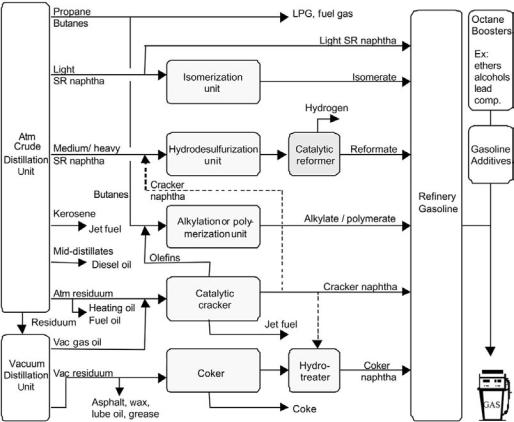
Hydrotreated (desulfurized) medium naphtha is the favored feedstock for catalytic reforming, although full-range stocks are sometimes processed if benzene is a desired product. The light naphtha is preferentially upgraded by isomerization whilst the heaviest part of the naphtha is often included in the light gas oil fraction (jet fuel/diesel). Figure 1 gives an example of a processing scheme for refinery gasoline production with catalytic reforming.
2.2Naphtha Composition
Hydrocarbons
Paraffins or alkanes are saturated aliphatic hydrocarbons with the general formula CnH2nþ2. They are either straight-chain (n-paraffins) or branched structures (i-paraffins). The boiling point increases by about 25–308C for each carbon
Figure 1 Example of a processing scheme for refinery gasoline production with catalytic reforming.
4 |
Prestvik et al. |
atom in the molecule, and the boiling point of an n-paraffin is always higher than that of the i-paraffin with the same carbon number. The density increases with increasing carbon number as well. Olefins or alkenes are unsaturated aliphatic hydrocarbons. Like the paraffins, they are either straight chains or branched structures, but contain one or more double bonds. Monoolefins have the general formula CnH2n. Naphthenes or cycloalkanes are saturated cyclic hydrocarbons that contain at least one ring structure. The general formula for mononaphthenes is CnH2n. The most abundant naphthenes in petroleum have a ring of either five or six carbon atoms. The rings can have paraffinic side chains attached to them. The boiling point and the density is higher than for any paraffin with the same number of carbon atoms. Aromatics have the general formula CnH2n26 and contain one or more polyunsaturated rings (conjugated double bonds). These benzene rings can have paraffinic side chains or be coupled with other naphthenic or aromatic rings. The boiling points and the densities of these polyunsaturated compounds are higher than that of both paraffins and naphthenes with the same carbon number. The reactivity of the unsaturated bonds make the C6, C7, and C8 aromatics or BTX (benzene, toluene, xylenes) important building blocks for the petrochemical industry. Aromatics have high octane numbers.
The composition of a given naphtha depends on the type of crude oil, the boiling range of the naphtha, and whether it is obtained directly from crude oil distillation or produced by catalytic or thermal cracking of heavier oil fractions. A typical straight-run medium naphtha contains 40–70 wt % paraffins, 20– 50 wt % naphthenes, 5–20 wt % aromatics, and only 0–2 wt % olefins. Naphtha produced by fluid catalytic cracking (FCC), coking, or visbreaking may contain 30–50 wt % olefins. Table 2 shows the hydrocarbon composition for different naphtha streams originating from a given crude.
In general, the paraffinicity decreases when the boiling point of the naphtha increases (Fig. 2). At the same time the complexity grows because the number of possible isomers increases exponentially with the carbon number. The number of detectable individual compounds in naphthas ranges typically from 100–300 for straight-run medium naphthas to beyond 500 for full-range stocks containing cracked material (additional olefins). In Table 3 the concentration of individual compounds detected in a medium straight-run naphtha is listed. Components like n-heptane, n-octane, methylcyclohexane, toluene, ethylbenzene, and xylenes are usually present in significant concentrations, whereas a number of C7 –C9þ paraffin and naphthene isomers are usually present in much smaller amounts.
Heteroatomic Organic Compounds, Water, and Metallic
Constituents
Sulfur is an important heteroatomic constituent in petroleum. The concentration is highly dependent on the type of crude oil and may range from virtually zero to

Table 2 Typical Compositions and Characteristics of Refinery Naphtha Streams Originating from the Same Crude Oil
|
Paraffins |
Olefins |
Naphth. |
Aromatics |
Density |
IBP–FBP |
Crude |
|
Stream |
(wt %) |
(wt %) |
(wt %) |
(wt %) |
(g/ml) |
(8C) |
(wt %) |
|
|
|
|
|
|
|
|
|
|
Light SR |
55 |
— |
40 |
5 |
0.664 |
C5 |
–90 |
3.2 |
Medium SR |
31 |
— |
50 |
19 |
0.771 |
90 |
–150 |
8.6 |
Heavy SR |
30 |
— |
44 |
26 |
0.797 |
150 |
–180 |
4.7 |
FCC |
34 |
23 |
11 |
32 |
0.752 |
C5 |
–220 |
20 |
Light VB |
64 |
10 |
25 |
1 |
0.667 |
C5 |
–90 |
— |
Heavy VB |
46 |
30 |
16 |
8 |
0.750 |
90 |
–150 |
— |
|
|
|
|
|
|
|
|
|
SR, straight-run; FCC, fluid catalytic cracker; VB, visbreaker; IBP, initial boiling point; FBP, final boiling point.
Reformate and Naphtha of Analysis Compositional
5
6 |
Prestvik et al. |
Figure 2 Hydrocarbon composition as a function of boiling point upon distillation of a North Sea crude.
more than 5% by weight. The sulfur tends to be more concentrated in the heavy end of the crude oil, which means that only ppm levels of sulfur are found in straight-run naphtha fractions. Still, even small concentrations are of great importance when it comes to processing the feedstock or using it directly as fuel. Sulfur poisons the noble-metal catalyst used in reforming and also promotes formation of undesirable SOx during combustion. Cracker and coker naphthas originating from heavier oil fractions often contain much more sulfur, up to a few thousand ppm. Sulfur is removed from naphtha by hydrotreating, which means conversion to H2S over a hydrotreating catalyst under hydrogen pressure. Hydrotreating is described more extensively in Chapter 4. The types of sulfur compounds found in crude oil are many: mercaptans, sulfides, disulfides, cyclic sulfides, alkylthiophenes, benzothiophenes, sulfates, traces of sulfuric acid, and sulfur oxides. In the naphtha boiling range thiophenes, noncyclic mercaptans and sulfides are the major groups. Identified sulfur compounds in naphtha are shown in Figure 3.
Organic nitrogen is present in even smaller concentrations than sulfur in the crude oil (,1.0 wt %) and mostly in the higher boiling point fractions. The compounds are usually classified as basic or nonbasic. Basic compounds are

Table 3 Hydrocarbon Compositiona in a Straight-Run Naphtha from North Sea Crude, Identified by GC
Compound |
Wt % |
Compound |
Wt % |
Compound |
Wt % |
Compound |
Wt % |
2,4-Dm-Pentane |
0.018 |
3,3-Dm-Pentane |
0.078 |
2-Me-Hexane |
2.287 |
2,3-Dm-Pentane |
1.140 |
1,1-Dm-CyC5 |
0.716 |
3-Me-Hexane |
3.216 |
c-1,3-Dm-CyC5 |
1.742 |
t-1,3-Dm-CyC5 |
1.650 |
t-1,2-Dm-CyC5 |
3.328 |
C7 Olefin 7 |
0.017 |
n-Heptane |
7.885 |
Me-CyC6 |
17.38 |
1,1,3-Tm-CyC5 |
0.866 |
2,2-Dm-Hexane |
0.105 |
Et-CyC5 |
1.056 |
2,2,3-Tm-Pentane |
0.409 |
2,4-Dm-Hexane |
0.595 |
ct-124-Tm-CyC5 |
0.990 |
3,3-Dm-Hexane |
0.137 |
tc-123-Tm-Pentane |
1.051 |
2,3,4-Tm-Pentane |
0.162 |
Toluene |
6.765 |
1,1,2-Tm-CyC5 |
0.308 |
2,3-Dm-Hexane |
0.452 |
2-Me-3-Et-Pentane |
0.180 |
2-Me-Heptane |
2.741 |
c-1,4-Dm-CyC6 |
0.914 |
n-Octane |
5.263 |
iPr-CyC5 |
0.065 |
C8 naphthene 6 |
0.074 |
c-2-Octane |
0.066 |
c-1,2-Et-Me-CyC5 |
0.154 |
2,2-Dm-Heptane |
0.089 |
c-1,2-Dm-CyC6 |
0.279 |
2,2,3-Tm-Hexane |
0.106 |
2,4-Dm-Heptane |
0.276 |
4,4-Dm-Heptane |
0.035 |
Et-CyC6 |
3.052 |
2-Me-4-Et-Hexane |
0.038 |
2,6-Dm-Heptane |
0.719 |
1,1,3-Tm-CyC6 |
0.918 |
1,1,4-Tm-CyC6 |
0.136 |
2,5-Dm-Heptane |
0.394 |
3,5-Dm-Heptane |
0.205 |
C9 naphthene 3 |
0.179 |
C9 naphthene 4 |
0.078 |
Ethylbenzene |
1.265 |
C9 naphthene 5 |
0.226 |
tt-1,2,4-Tm-CyC6 |
0.472 |
C9 naphthene 7 |
0.050 |
C9 naphthene 8 |
0.031 |
m-Xylene |
3.039 |
C9 naphthene 16 |
0.784 |
C9 naphthene 18 |
0.152 |
C9 naphthene 20 |
0.269 |
C9 naphthene 22 |
0.013 |
C9 naphthene 23 |
0.039 |
C9 naphthene 24 |
0.079 |
C9 naphthene 26 |
0.052 |
C9 naphthene 29 |
0.036 |
C9 naphthene 31 |
0.070 |
n-Nonane |
2.226 |
C9 naphthene 32 |
0.062 |
C9 naphthene 33 |
0.046 |
iPr-Benzene |
0.205 |
C9 olefin 13 |
0.342 |
C9 naphthene 35 |
0.206 |
iPr-CyC6 |
0.009 |
2,2-Dm-Octane |
0.067 |
C10 paraffin 1 |
0.109 |
C10 paraffin 2 |
0.015 |
C9 naphthene 36 |
0.053 |
n-Pr-CyC6 |
0.519 |
C10 paraffin 3 |
0.090 |
n-But-CyC5 |
0.096 |
C10 naphthene 2 |
0.074 |
C10 naphthene 3 |
0.020 |
C10 naphthene 4 |
0.041 |
1-Me-2-Et-Benz |
0.225 |
3-Et-Octane |
0.094 |
C10 naphthene 10 |
0.014 |
C10 naphthene 11 |
0.030 |
C10 paraffin 8 |
0.040 |
3-Me-Nonane |
0.073 |
C10 paraffin 9 |
0.021 |
1,2,4-Tm-Benz |
0.281 |
C10 naphthene 14 |
0.067 |
C10 naphthene 15 |
0.081 |
i-But-CyC6 |
0.010 |
C10 naphthene 16 |
0.012 |
C10 naphthene 17 |
0.013 |
C10 naphthene 18 |
0.013 |
i-But-Benzene |
0.037 |
s-But-Benzene |
0.055 |
n-Decane |
0.258 |
C10 naphthene 20 |
0.013 |
1,2,3-Tm-Benz |
0.079 |
1,3-Me-iPr-Benz |
0.087 |
1,4-Me-iPr-Benz |
0.132 |
C10 naphthene 22 |
0.119 |
Indane |
0.070 |
C10 naphthene 24 |
0.016 |
C10 naphthene 25 |
0.030 |
C11 paraffin 2 |
0.040 |
(Table continues)
Reformate and Naphtha of Analysis Compositional
7

8
Table 3 Continued
Compound |
Wt % |
Compound |
Wt % |
Compound |
Wt % |
Compound |
Wt % |
4-Me-Heptane |
0.888 |
p-Xylene |
0.927 |
|
3,4-Dm-Hexane |
0.123 |
2,3-Dm-Heptane |
0.860 |
|
C8 naphthene 1 |
0.064 |
C9 naphthene 9 |
0.048 |
|
C8 naphthene 2 |
0.065 |
3,3-Dm-Heptane |
0.090 |
|
c-1,3-Dm-CyC6 |
2.904 |
4-Et-Heptane |
0.105 |
|
3-Me-Heptane |
1.699 |
4-Me-Octane |
0.433 |
|
3-Et-Hexane |
1.664 |
2-Me-Octane |
0.570 |
|
1,1-Dm-CyC6 |
0.454 |
C9 |
naphthene 11 |
0.124 |
t-13-Et-Me-CyC5 |
0.374 |
3-Et-Heptane |
0.157 |
|
c13-Et-Me-CyC5 |
0.413 |
3-Me-Octane |
0.571 |
|
t-12-Et-Me-CyC5 |
0.733 |
C9 |
naphthene 11 |
0.050 |
1-Me-1-Et-CyC5 |
0.107 |
o-Xylene |
1.260 |
|
t-1,2-Dm-CyC6 |
1.649 |
C9 |
naphthene 12 |
0.061 |
cc-123-Tm-CyC5 |
0.023 |
C9 |
naphthene 14 |
0.023 |
3,3-Dm-Octane |
0.250 |
n-But-CyC6 |
0.036 |
|
C10 paraffin 4 |
0.059 |
C10 naphthene 30 |
0.011 |
|
n-Pr-Benzene |
0.278 |
1,3-De-Benzene |
0.012 |
|
C10 naphthene 5 |
0.065 |
1,3-Me-nPr-Benz |
0.026 |
|
2,6-Dm-Octane |
0.145 |
1,4-Me-nPr-Benz |
0.009 |
|
C10 naphthene 7 |
0.039 |
n-But-Benzene |
0.012 |
|
1-Me-3-Et-Benz |
0.383 |
13-Dm-5Et-Benz |
0.009 |
|
1-Me-4-Et-Benz |
0.150 |
C10 naphthene 31 |
0.014 |
|
C10 |
naphthene 9 |
0.063 |
1,2-Me-nPr-Benz |
0.015 |
1,3,5-Tm-Benz |
0.166 |
14-Dm-2Et-Benz |
0.015 |
|
C10 |
paraffin 5 |
0.076 |
12-Dm-4Et-Benz |
0.013 |
C10 |
paraffin 6 |
0.042 |
n-Undecane |
0.018 |
C10 |
paraffin 7 |
0.030 |
|
|
4-Me-Nonane |
0.025 |
|
|
|
aStructures not fully identified are numbered according to type of compound and carbon number.
.al et Prestvik

Compositional Analysis of Naphtha and Reformate |
9 |
Figure 3 Identified sulfur compounds in naphtha.
pyridine, piperidine, or indoline derivatives whereas the nonbasic are pyrrole derivatives. Straight-run naphtha fractions usually contain sub-ppm concentrations of nitrogen, whereas cracker and coker naphthas may contain typically 10–100 ppm by weight. Nitrogen is poisonous to the reforming catalyst as it adsorbs strongly on its acidic sites. Common N-containing components in the naphtha boiling range are shown in Figure 4.
Oxygen-containing organic compounds are normally present only in the heavy fractions of the crude. These are phenols, furanes, carboxylic acids, or esters. The different acids account for the petroleum’s acidity. High acidity can cause serious corrosion problems in the refinery. Little or no organic oxygen is found in the naphtha fractions.
Water is normally present in crude oil to some extent, partly dissolved in the oil and possibly as a separate water phase. Naphtha fractions will to some extent dissolve moisture during handling and storage. Water has a high heat of
Figure 4 Identified nitrogen compounds in straight-run naphtha.
10 |
Prestvik et al. |
vaporization compared to petroleum and complicates distillation.[3] Water also results in catalyst deactivation by neutralizing the acidic sites of the reforming catalyst.
The heaviest oil fractions rich in resins and asphaltenes contain metallic compounds. These are usually organometallic complexes in the form of porphyrins with Ni2þ or vanadium oxide (1þ) cations. These compounds are not found in the naphtha boiling range. However, other metallic constituents, such as iron (dust or scale or organometallic compounds) from pipeline corrosion or silicon compounds (siloxanes) originating from antifoam chemicals, might cause problems in catalytic reforming. Iron dust can cause pressure drop problems whereas the silicon compounds adsorb onto and deactivate the reforming catalyst.
3EFFECT OF NAPHTHA COMPOSITION ON PROCESS PERFORMANCE AND PRODUCT QUALITY IN CATALYTIC REFORMING
The hydrocarbon composition, the naphtha boiling range, and the concentration of impurities affect the quality of the reformate product. The same feedstock characteristics also influence the reforming process, including the performance and lifetime of the catalyst. In order to understand these relationships it is useful first to define some quality requirements of the product (gasoline specifications, octane ratings) and to describe briefly the reactions involved in the catalytic reforming process.
3.1Gasoline Quality Requirements
The purpose of catalytic reforming is primarily to increase the octane number of the naphtha feedstock to a level that makes the reformate product suitable as a gasoline blend stock. The octane number represents the ability of a gasoline to resist knocking during combustion of the air–gasoline mixture in the engine cylinder. European gasoline today must have research octane number (RON) ratings of 95–98. Such high octane numbers allow compression ratios needed for optimal fuel economy of present gasoline engines.
Gasoline must have a number of other properties in order to function properly and to avoid damage to the environment. Olefins have a tendency to form gums by polymerization and oxidation of olefins, and can foul the engine. In order to avoid emission of volatile light hydrocarbons, the vapor pressure (often measured as Reid vapor pressure, RVP) must be limited. Certain compounds, such as benzene, are classified as carcinogenic and represent a health hazard. Tetraalkyllead has long been used as an octane booster, but will accumulate in

Compositional Analysis of Naphtha and Reformate |
11 |
Table 4 Present Gasoline Specifications for the United States, Europe, and Japan[4 – 6]
Max values |
USA |
EU |
Japan |
|
|
|
|
RVP (kPa) |
— |
60 |
78 |
Sulfur (wppm) |
50 |
150a |
100 |
Oxygen (wppm) |
2.2 |
2.7 |
— |
Benzene (vol %) |
1.0 |
1 |
— |
Aromatics (vol %) |
35 |
45 |
— |
Olefins (vol %) |
15 |
18 |
— |
Lead (g/L) |
— |
0.005 |
— |
a50 wppm from 2005.
nature, and is today strictly regulated and largely eliminated. Combustion of carbon leads to CO2 (global warming problem) and poisonous CO. Combustion of sulfur and nitrogen (from air) leads to production of SOx and NOx that cause acid rain pollution. The volatile organic compounds produced during combustion of heavy aromatics are toxic in nature and are involved also in the photochemical reaction with NOx to form ground-level ozone (smog). Exhaust catalysts have reduced emissions of NOx to some extent, but present catalysts are sensitive to sulfur. Stringent regulations on the sulfur level of gasoline are therefore being developed. The present gasoline specifications (Table 4) set upper limits for the allowable concentrations of sulfur, benzene, olefins, and aromatics. Some countries have tax incentives for 50 or 10 ppm sulfur.
3.2The Octane Number
In practice two octane ratings are measured, the research octane number (RON) and the motor octane number (MON), which differ in test procedure used. RON represents the engine performance at low speed whereas MON is representative for high-speed driving. By definition, the octane number of n-heptane is zero and the octane number of isooctane (2,2,4-trimethylpentane) is 100. The octane number for a gasoline is defined as the volume percent of isooctane in blending with n-heptane that equals the knocking performance of the gasoline being tested. Some gasoline components have octane numbers exceeding 100 and have to be characterized by use of mixtures. A common mixture contains 20% of the actual compound and 80% of an n-heptane/isooctane (40 : 60) mixture. A hypothetical blending octane number is then obtained by extrapolating from 20% to 100% concentration. The blending octane number is specific for the mixture and usually different from the octane number of the pure component, as seen for a range of different hydrocarbons with octane numbers less than 100 in Table 5.

Table 5 Pure and Blendinga Research Octane Numbers of Hydrocarbons[7]
|
RON |
RON |
|
|
RON |
Hydrocarbon |
pure |
blending |
Hydrocarbon |
RON pure |
blending |
|
|
|
|
|
|
Paraffins |
|
|
n-Butane |
94.0 |
113 |
Isobutane |
.100 |
122 |
n-Pentane |
61.8 |
62 |
2-Methylbutane |
92.3 |
100 |
n-Hexane |
24.8 |
19 |
2-MethylPentane |
73.4 |
82 |
2,2-Dimethylbutane |
91.8 |
89 |
n-Heptane |
0.0 |
0 |
3-Methylhexane |
52 |
56 |
2,3-DimethylPentane |
91.1 |
88 |
2,2,3-Trimethylbutane |
.100 |
112 |
n-Octane |
,0 |
218 |
3,3-Dimethylhexane |
75.5 |
72 |
2,2,4-TrimethylPentane |
100.0 |
100 |
n-Nonane |
,0 |
218 |
2,2,3,3-TetramethylPentane |
.100 |
122 |
n-Decane |
,0 |
241 |
Olefins |
|
|
1-Hexene |
76.4 |
96 |
1-Heptene |
54.5 |
65 |
2-Methyl-2-hexene |
90.4 |
129 |
2,3-Dimethyl-1-pentene |
99.3 |
139 |
Naphthenes |
|
|
Cyclopentane |
.100 |
141 |
Cyclohexane |
83.0 |
110 |
Methylcyclopentane |
91.3 |
107 |
Methylcyclohexane |
74.8 |
104 |
t-1,3-Dimethylcyclopentane |
80.6 |
90 |
1,1,3-Trimethylcyclopentane |
87.7 |
94 |
Ethylcyclohexane |
45.6 |
43 |
Isobutylcyclohexane |
33.7 |
38 |
Aromatics |
|
|
Benzene |
— |
98 |
Toluene |
.100 |
124 |
Ethylbenzene |
.100 |
124 |
o-Xylene |
— |
120 |
m-Xylene |
.100 |
145 |
p-Xylene |
.100 |
146 |
n-Propylbenzene |
.100 |
127 |
Isopropylbenzene |
.100 |
132 |
1-Methyl-3-ethylbenzene |
.100 |
162 |
1,3,5-Trimethylbenzene |
.100 |
170 |
n-Butylbenzene |
.100 |
114 |
1-Methyl-3-isopropylbenzene |
— |
154 |
1,2,3,4-Tetramethylbenzene |
.100 |
146 |
aObtained using a 20% hydrocarbon –80% 60 : 40 mixture of isooctane and n-heptane.
12
.al et Prestvik
Compositional Analysis of Naphtha and Reformate |
13 |
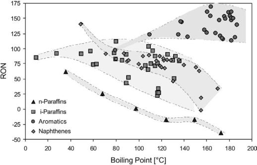
Table 5 shows that aromatics generally have much higher octane numbers than naphthenes, olefins, and paraffins and are therefore desired reformate hydrocarbon components. The octane number of the aromatics (except for benzene) is always above 100. Straight-chain paraffins have very low octane numbers (RON , 0 for n-octane and n-nonane), but the octane number increases markedly with the degree of branching (RON . 100 for 2,2,3-trimethylbutane). Light olefins and naphthenes generally have higher RON than the paraffins, but as for the n-paraffins the octane number declines as the number of carbon atoms increases. This decline is much less pronounced for the isoparaffins. Considering the boiling range of gasoline (C5 –C12 hydrocarbons) and the above comparison, visualized in Figure 5, an increase in the octane number of the reformate can best be obtained by transformation of naphthenes into aromatics and of linear paraffins into branched paraffins or aromatics. These transformations are the key reactions of the catalytic reforming process.
3.3Catalytic Reforming Process
Catalytic reforming is carried out at elevated temperature (450–5208C) and moderate pressure (4–30 bar). By use of a proper catalyst in three or four serial reactors and in the presence of hydrogen (H2/oil equal to 4–6 mol/
Figure 5 Octane numbers vs. boiling point for hydrocarbon families.[7,8]
14 |
Prestvik et al. |
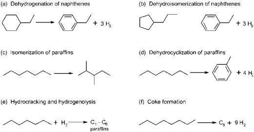
Figure 6 Major reactions in catalytic reforming of naphtha.
mol), naphthenes are transformed into aromatics by dehydrogenation and straight-chain paraffins into branched paraffins by isomerization. Paraffins also undergo dehydrocyclization to form aromatics. Other important reactions are hydrogenolysis and hydrocracking (carbon–carbon bond scissions), which result in low molecular weight paraffins, and coke formation that will eventually deactivate the catalyst. Figure 6 shows the major reforming reactions.
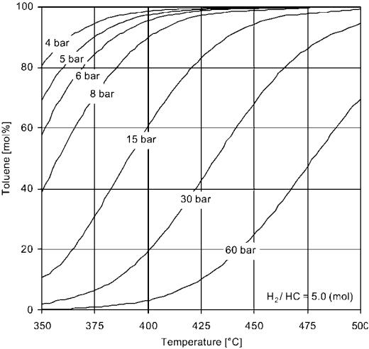
The hydrogen produced in catalytic reforming has become increasingly valuable since it is used in hydroprocessing units for removal of sulfur and nitrogen as well as for hydrocracking. The formation of aromatics from naphthenes is a very rapid endothermic reaction. It is thermodynamically favored by high temperature and low pressure, as illustrated by the equilibrium between toluene and the C7 naphthenes (Fig. 7). Olefins are readily hydrogenated and at equilibrium only small concentrations can exist with the hydrogen partial pressures normally used in reforming. The isomerization of paraffins is also rapid and mostly thermodynamically controlled. The dehydrocyclization of paraffins is a much slower reaction and kinetically controlled. Hydrocracking rates increase with the pressure and lower the reformate yield. Coking, which is the main cause for catalyst deactivation, is very slow but increases rapidly at low hydrogen pressure and high temperature. In order to optimize the hydrogen and aromatics formation, and to avoid severe yield loss due to hydrocracking, the choice is to operate at a high temperature and at the lowest possible hydrogen pressure, although the latter always is a trade-off with catalyst stability.
The catalyst is bifunctional in the sense that it contains both a metallic function (platinum) that catalyzes dehydrogenation reactions and an acidic
Compositional Analysis of Naphtha and Reformate |
15 |
Figure 7 Effect of temperature and pressure on the concentration of toluene in thermodynamic equilibrium with H2 and C7 naphthenes.[9]
function (chlorided alumina) that catalyzes isomerization reactions. Platinum, which is usually used with a second metal, needs to be highly dispersed on the acidic carrier in order to maintain high activity and selectivity throughout a commercial cycle. In units designed for periodic regeneration of the catalyst (semiregenerative reforming), a cycle typically lasts 1–2 years. Most new units are designed with continuous catalyst regeneration implying that each catalyst particle has a cycle time of typically 6–8 days between regenerations. Two catalyst formulations prevail commercially: Pt-Re/Al2O3 and Pt-Sn/Al2O3. The former is the most stable and is preferred in semiregenerative units, whereas the latter has the highest selectivity at low pressure and is the best choice in continuous reforming units. These catalysts are sensitive to sulfur which adsorbs
16 |
Prestvik et al. |
(reversibly) on the platinum crystallites. Sulfur can be removed by hydrotreatment of the naphtha feedstock. The water content must also be kept low to avoid leaching of chloride and thus loss of acid strength. Metallic poisons are relatively rare, but iron from plant corrosion and silicon originating from antifoam chemicals can affect catalyst activity.
Effect of Naphtha Hydrocarbon Composition
The distribution of paraffins (P), olefins (O), naphthenes (N), and aromatics (A) in the naphtha determines the richness of the feedstock. A high concentration of aromatics automatically means that the octane level is quite high. The naphthenes are transformed into aromatics with high selectivity and a high octane is therefore easily achieved. A paraffinic (or paraffinic–olefinic) feedstock will have a low octane number. Severe reaction conditions are required to reach a specified RON level, and the yield loss and coke laydown will be significant. The richness of a naphtha is therefore usually rated by its N þ A or N þ 2A value. Figure 8 illustrates how the reforming reactor temperature decreases and the liquid yield of reformate increases when the feedstock N þ A values increase.
Figure 8 Reactor temperature and reformate yield as a function of naphtha N þ A (naphthenes þ aromatics) value. Reaction conditions: 100 RON, P ¼ 30 bar, WHSV ¼ 2.0 h 1, and H2/HC ¼ 4.5.
Compositional Analysis of Naphtha and Reformate |
17 |
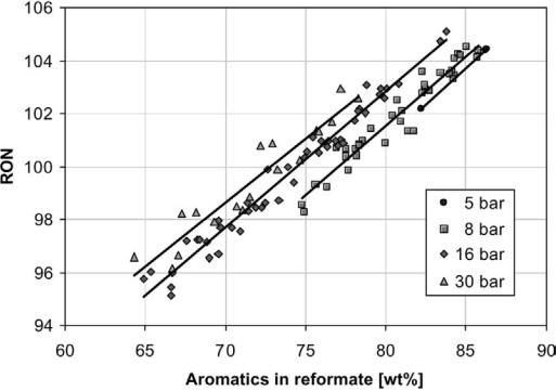
Figure 9 RON as a function of aromatics concentration from a number of pilot experiments using a range of different naphthas and variable reaction conditions.
The hydrocarbon composition in the naphtha does not affect the reformate composition much. The reformate consists mainly of paraffinic and aromatic hydrocarbons since the large part of the naphthenes is consumed in the reaction. There is a near-linear relationship between the RON value and the concentration of aromatics (Fig. 9). Thus, regardless of feedstock composition, when operating with a constant RON level in the product, the aromatic and paraffin concentrations are usually fixed within narrow limits. However, as shown in Figure 9, the RON–aromatics relationship changes somewhat with reaction pressure. At elevated pressures the concentration of high-octane cracked products (C5 and C6 isoparaffins) increases, and subsequently less aromatics are required to reach a specified RON in the product.
Effect of Naphtha Boiling Range
The boiling range of the naphtha feedstock is a key factor in catalytic reforming. The initial and final boiling points (IBPs and FBPs) and the boiling point distribution not only determine the carbon number distribution of the product but
18 |
Prestvik et al. |
greatly affect reaction conditions, and thus reformate yields, as well as the rate of catalyst deactivation.
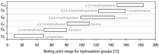
Although the carbon number distribution in the feedstock and in the reformate product are strongly related, the boiling points increase somewhat during reaction due to aromatics formation. As an illustration, the FBP typically increases by 208C at low to intermediate reaction pressures (,20 bar). The increase in FBP from feedstock to product is slightly smaller at higher pressures because the heaviest components undergo additional hydrocracking. Based on boiling points of individual hydrocarbons in naphtha, Figure 10 shows the boiling range for each carbon number group. Although azeotropic phenomena among various compounds exist, it is still possible by distillation to separate the feedstock fairly well according to carbon number. Above 1008C the overlap in boiling range between the groups is significant and separation becomes increasingly difficult.
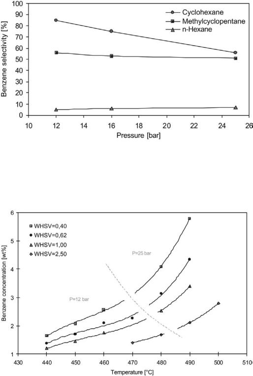
The choice of naphtha boiling range depends on the intended use of the reformate product. When catalytic reforming is used mainly for benzene, toluene, and xylenes (BTX) production, a C6 –C8 cut (IBP–FBP 60–1408C), rich in C6, is usually employed. For high-octane gasoline production, especially when the reformate constitutes a major part of the gasoline pool, a C7 –C9 cut (IBP–FBP 90–1608) is the preferred choice. The C6 hydrocarbons may be removed to avoid the benzene in the naphtha and to avoid further benzene formation from the C6 naphthenes. The benzene yield from cyclohexane and methylcyclohexane (primary production) is significant, as illustrated in Figure 11. These reactions are controlled by thermodynamics and favored by low pressure. Benzene is also formed by dealkylation of heavier aromatics (secondary production). This reaction is kinetically controlled and favored by high temperature and low space velocity (Fig. 12).
The benzene selectivity from substituted aromatics increases with the length of the side chain (n-butylbenzene . n-propylbenzene) and with the degree
Figure 10 Boiling range of naphtha hydrocarbons grouped by carbon number.[8]
Compositional Analysis of Naphtha and Reformate |
19 |
Figure 11 Benzene selectivity (percentage of the components feed concentration found as wt % benzene yield) vs. pressure in semiregenerative reforming with PtRe catalyst. RON ¼ 101.
Figure 12 Benzene in reformate as a function of reaction temperature and space velocity using a feedstock with 0.23 wt % C6 hydrocarbons.

20 |
Prestvik et al. |
of sidechain branching (i-propylbenzene . n-propylbenzene). Toluene has a relatively low selectivity to dealkylation. However, considering the very high concentrations in the reformate, the contribution from toluene and also from methylyclohexane (which forms toluene) to the secondary benzene production is significant.
The heavy end containing C10þ hydrocarbons is the least favorable with regard to processing, particularly in semiregenerative units, due to high deactivation rates. Figure 13 shows how the relative deactivation rate increases with the naphtha FBP. This effect is not related to the reaction temperature but to the amount of coke precursor in the feed.[10] Alkyl-substituted C10þ aromatics (and polycyclics) have been identified as strong coke precursors. For continuous reforming units, heavy stocks can be processed if the coke burning capacity is sufficient. The cutpoint in the light end of the naphtha also affects the deactivation rate. When the IBP is increased the naphtha becomes richer and the same octane number can be achieved at lower reaction temperatures.
The legislative requirements for sulfur removal from gasoline and diesel have increased hydrogen use in the refineries; hence, refiners are looking for ways to maximize their hydrogen yields. The optimal feedstock to a reformer with respect to hydrogen yield is a C6 –C9 cut that contains the highest naphthene concentrations. No hydrogen can be produced from the C5 fraction and little hydrogen is produced from the C10þ hydrocarbons, which are highly susceptible to hydrocracking. The highest yields of hydrogen are obtained at low pressures and high temperatures when the conversion of naphthenes and paraffins into
Figure 13 The deactivation rate (measured as the temperature rise needed to maintain 102.4 RON relative to a base naphtha) as a function of final boiling point (FBP).[10]
Compositional Analysis of Naphtha and Reformate |
21 |
aromatics is high. The temperature must, however, be kept below a point when hydrocracking becomes important, which would lower the yield of both hydrogen and reformate. The octane number during maximized hydrogen production is typically in the order of 102–105 RON, and it follows that the deactivation rate is high.
Effect of Naphtha Sulfur Content
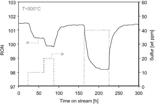
Reforming catalysts are sensitive to sulfur impurities in the naphtha feedstock. The surface platinum atoms of the catalyst convert the sulfur compounds into H2S molecules that readily adsorb onto the surface metal atoms. The poisoned platinum atoms are no longer active and the temperature must be increased to maintain RON (i.e., produce aromatics by dehydrogenation). Reformate yield decreases somewhat due to the temperature rise but not as much as normally observed. This is due to the reduced methane production by the metal-catalyzed hydrogenolysis reaction. However, the rate of deactivation increases according to the temperature increase. The adsorption of sulfur is strong but reversible. A given sulfur concentration in the feedstock results in a specific sulfur coverage. However, if the sulfur is removed from the naphtha, the activity will eventually return to very near the initial level as shown in Figure 14.
Figure 14 Effect of sulfur upset on RON level at T ¼ 5008C, P ¼ 16 bar, WHSV ¼ 2.0 h 1, and H2/HC ¼ 4.3.

22 |
Prestvik et al. |
4ANALYSIS METHODS
The high complexity of naphtha and reformate fractions requires advanced techniques to obtain a complete compositional analysis and to determine the chemical and physical parameters needed for the refiner. Many different approaches exist, and the choice of analytical method depends on the needed resolution, the analysis time, and the cost. For industrial products that must meet defined specifications, refiners are required to follow standardized analysis procedures. The American Society for Testing and Materials (ASTM) is one of several recognized organizations for standardization. This chapter will concentrate on the most common methods for determining hydrocarbon composition, distillation range, octane numbers, and sulfur/nitrogen contents. Examples of both ASTM and nonstandardized methods are included.
4.1Hydrocarbon Composition
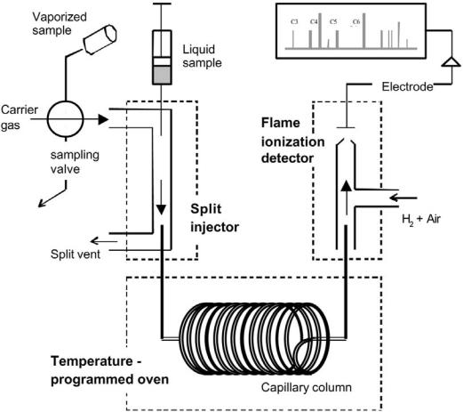
The most powerful and widely used technique for analysis of hydrocarbons in naphthas or reformates is gas chromatography (GC). This is a separation method in which the sample is injected into a carrier gas stream, usually helium, and brought through a dedicated capillary column allowing transport of the different molecules at different rates (Fig. 15). The samples may be gaseous or liquid. Vaporized sampling is usually preferred for on-line product testing in research laboratories. An adjustable split injector can strongly reduce the sample amount and thereby avoid column overloading and subsequent separation problems. Nonpolar, cross-linked methylsiloxane columns
give elution times close to the order of increasing boiling point. The columns have diameters of 0.1–0.5 mm and the length ranges from a few meters up to 100 m. A flame ionization detector creates and detects a signal proportional to the concentration of each hydrocarbon as the components exit the column. It operates by collecting (by an electrode) the ions of the flame produced during combustion of the hydrocarbon. The detector response is approximately proportional to the weight of carbon present,[11] which greatly simplifies quantitative analysis.
The rate of hydrocarbon transport through the column is dependent on the carrier gas velocity, adjusted for the injector pressure and the oven temperature. The lightest hydrocarbons (methane and ethane) are transported very quickly through the column and separation requires low temperature (ambient). On the
Compositional Analysis of Naphtha and Reformate |
23 |
Figure 15 Schematic illustration of gas chromatography (GC) with gas/liquid sampling, split injection, and flame ionization detection (FID).
other hand, the heaviest aromatics need a temperature of 2008C or more in order not to adsorb strongly at the column front. Thus, an advanced temperature program and column pressure selection is required to optimize separation and time consumption of a GC analysis. The column material and length, the detector temperature, the carrier gas type, and the split flow rate also affect the separation.
Gas chromatography is not an identification method. In order to identify the large number of peaks in the chromatogram, the system must be calibrated. This can best be obtained by coupling a mass spectrometer to the column exit of an identical chromatographic setup (gas chromatography–mass spectrometry, GCMS). Most of the resolved peaks are identified from MS spectra libraries. The equipment is costly and such an analysis is time consuming, but a good ‘peak library’ for the GC user is obtained given that the column separation is good. In practice, the ‘heavy region’ of the chromatogram is never fully resolved,

24 |
Prestvik et al. |
Table 6 Analysis of C5 –C12 PONA Hydrocarbons According to ASTM D5134 |
|
|
|
Column |
50 m cross-linked methylsiloxane |
Temp. program |
358C (30 min) ! 2008C, 28C/min (20 min) |
Carrier gas |
Helium, 215 kPa |
Injector |
Split, 200 ml/min; T ¼ 2008C |
Detector |
FID; T ¼ 2508C |
Sample size |
0.1 ml (liquid) |
|
|
especially when additional peaks created by the presence of olefins exist, as is the case for naphthas from catalytic cracking.
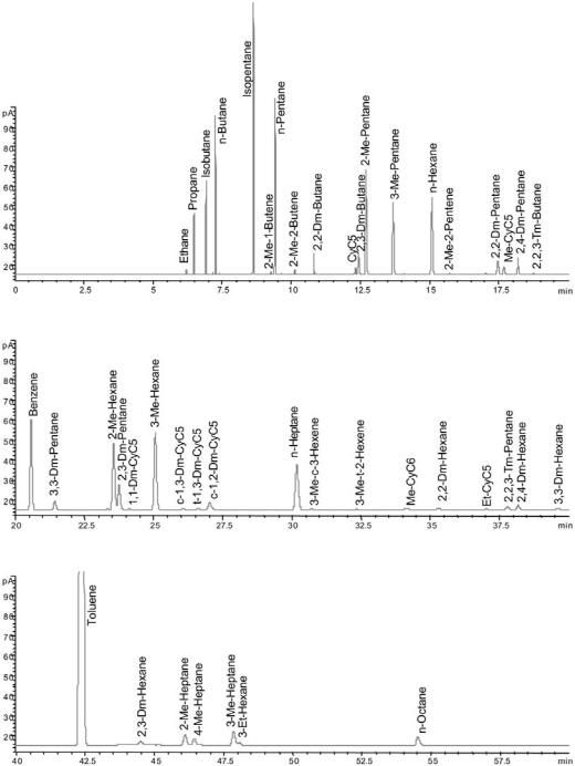
ASTM D5134 is a GC method for PONA analysis in naphthas and reformates (C5 –C12). The method, described in Table 6, is limited to straight-run naphthas, reformates, and alkylates because the olefin content is limited to 2% and all components eluting after n-nonane (BP . 150.88C) are collected as one peak. The analysis time is 122 min. Table 7 describes an even more timeconsuming method that applies a longer column, a lower initial temperature, and a more complex temperature program designed to separate most C1 –C12 hydrocarbons in naphthas and reformates. A chromatogram with identified peaks obtained using this method on a reformate sample is shown in Figure 16. Detection of most individual compounds is important for the understanding of the chemistry involved in catalytic reforming. As an example, a precise feedstock and product hydrocarbon analysis makes it possible by mass balance to calculate the amount of hydrogen produced by the reforming reactions. The data can also, based on simple models, be used to calculate density, vapor pressure, carbon and hydrogen content, and octane numbers. For the process engineer it is often sufficient to know the PONA group concentrations in order to verify the feedstock or product qualities, and the least time-consuming GC methods are chosen. Specialized methods for more precise analysis of single compounds are available.
Table 7 Comprhensive Laboratory Analysis for C1 –C12 PONA Hydrocarbons
Column |
100 m cross-linked methylsiloxane |
Temp. program |
308C (30 min) ! 508C, 18C/min (10 min) ! 1408C, |
|
28C/min (0 min) ! 2508C, 108C/min, (30 min) |
Carrier gas |
Helium, 300 kPa |
Injector |
Split, 800 ml/min; T ¼ 2508C |
Detector |
FID; T ¼ 2808C |
Sample size |
0.2 ml (liquid) |
|
|
Compositional Analysis of Naphtha and Reformate |
25 |
Figure 16 Chromatogram of reformate (liquid sample) using the GC method listed in Table 7. Page 1 of 2.
26 |
Prestvik et al. |
Figure 16 Continued.
Compositional Analysis of Naphtha and Reformate |
27 |
4.2Distillation Range
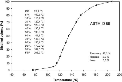
Knowledge about the boiling point distribution of gasolines is most frequently obtained by distillation according to ASTM D86. A batch distillation is conducted at atmospheric pressure and the resulting curve shows the temperature as a function of percent volume distilled. Automated instruments perform the measurement. Figure 17 shows an ASTM D86 distillation curve and tabulated values for a reformate sample.
Another way of analyzing the boiling range characteristics is to simulate the distillation by use of GC. By using an inert column stationary phase, the components elute in order of their boiling points. The ASTM D3710 method is specialized for gasoline fractions and gives the result within 15 min.
4.3Sulfur and Nitrogen Analysis
The fact that only small concentrations of sulfur and nitrogen poison reforming catalysts calls for highly accurate analysis methods, capable of measuring down to sub-ppm levels. Non-hydrotreated naphthas from thermal or catalytic cracking
Figure 17 Results for an ASTM D86 distillation of a reformate sample.

28 |
|
|
Prestvik et al. |
Table 8 Sulfur and Nitrogen Analysis Methods |
|
|
|
|
|
|
|
Target |
Technique |
ASTM |
Range (wppm)a |
|
|
|
|
N |
OC/chemiluminescence |
D4629 |
0.3–100 |
N |
OC/electrochemical detection |
D6366 |
0.05–100 |
S |
OC/microcoulometry |
D3120 |
3–100 |
S |
OC/UV fluorescence |
D5453 |
1–8000 |
S |
Hydrogenolysis |
D4045 |
0.02–10 |
S |
X-ray fluorescence |
D4294 |
.1000 |
S |
GC/selective sulfur detector |
D5623 |
0.1–100b |
aAnalytical range suggested by ASTM method. bConcentration range of each individual sulfur compound. OC, oxidative combustion.
processes may reach percent levels of sulfur and 100 ppm levels of nitrogen. Thus, versatile analysis methods covering sulfur and nitrogen from ppb up to percent levels are needed. A large number of methods and instrument types are available as shown in Table 8. Most analysis techniques are based on initial combustion of sulfur into SO2 or SO3 and of nitrogen into NO or NO2. The amount of these oxides can then be measured by techniques such as microcoulometry (sulfur), UV fluorescence (sulfur), chemiluminescence (nitrogen), and electrochemical detection (nitrogen). Nonoxidative techniques for sulfur analysis include hydrogenolysis, X-ray fluorescence, and, finally, GC with sulfur-selective detection methods such as atomic emission detection (AED), sulfur chemiluminescence detection (SCD), and flame photometric detection (FPD). The GC technique not only measures total sulfur but may also detect and distinguish among different sulfur compounds in the sample.
Sulfur and nitrogen analyzers have improved in recent years when it comes to detection limits. Pyrochemiluminescent nitrogen and pyrofluorescent sulfur technology are such examples and can be combined in one instrument and used on the same sample injection simultaneously. The principal reactions for the measurement of sulfur by pyrofluorescence are shown in Figure 18. Modern instruments give total nitrogen determinations from low ppb to 20 wt % and total sulfur determinations from low ppb up to 40 wt %. The analysis takes only a few minutes.
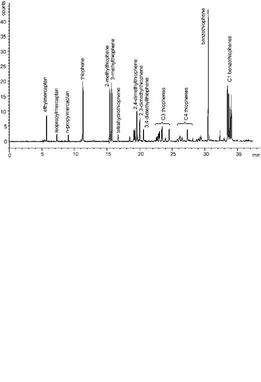
For research laboratories studying the chemistry of sulfur and its reactions, as in hydrotreatment, the available GC methods are most appealing. By extensive precalibration of such a system it is possible to identify the different sulfur structures present in the sample. Figure 19 shows a chromatogram from analysis of a cracker naphtha using AED. Integration of all peaks in the chromatogram
Compositional Analysis of Naphtha and Reformate |
29 |
Figure 18 Schematic illustration of total sulfur analysis by pyrofluorescence method.
yields the total sulfur concentration. Very good comparisons have been measured
between total sulfur analysis by GC/AED and sulfur analysis by pyrofluorescence.[12] The new SCD instruments[13] have extremely high sensitivity and are the choice for low-sulfur samples.[14]
Figure 19 GC/AED chromatogram showing the sulfur distribution in full-range catalytic cracker naphtha.

30 |
Prestvik et al. |
4.4Octane Number Determination
Octane ratings are measured directly using a single-cylinder reference motor (CFR engine).[15] The compression ratio and the fuel/air ratio are adjustable and
the engine is solidly built to withstand knocking without damage. The basic procedure is to increase the compression ratio of the engine until a ‘standard’ knocking intensity is indicated by a pressure detector in the combustion chamber.[15] The critical compression ratio is recorded and compared with two binary heptane–isooctane mixtures of neighboring composition. The fuel/air ratio is adapted in each case to obtain maximum knocking intensity; it is usually between 1.05 and 1.10. The octane number is calculated by linear interpolation, assuming the primary reference mixture has similar behavior as the fuel being tested. The distinctions between the two procedures of RON and MON measurement concern essentially the engine speed, temperature of admission, and spark advance as indicated in Table 9. The RON and MON methods simulate the engine performance when driving at low and high speed, respectively.
An alternative method for determination of the octane number of a gasoline is by means of calculation, using the hydrocarbon composition from GC analysis as input data. It is not a straightforward task to develop such a model because blending of different individual hydrocarbons does not result in an engine knocking performance as expected from the octane numbers of the individual components. Advanced models, both linear and nonlinear and based on a number of naphthas or reformates with variable compositions and cut points, have been put forward.
An approach to calculate the octane number based only on the total aromatics content is possible.[16] However, the RON–aromatics relationship is not accurate and changes significantly with reaction pressure as shown earlier in this chapter (Fig. 9). Walsh and coworkers[17] developed a linear RON calculation model based on GC analysis with capillary columns. A grouping technique is used
Table 9 Test Conditions for RON and MON Determination in CFR Engines[15]
|
RON method |
MON method |
Operating parameters |
ASTM D2699 |
ASTM D2700 |
|
|
|
Engine speed (rpm) |
600 |
90 |
Ignition advance (degrees before top dead center) |
13 |
14 to 26a |
Inlet air temperature (8C) |
48 |
— |
Fuel mixture temperature (8C) |
— |
149 |
Fuel/air ratio |
b |
b |
|
|
aVariable with the compression ratio.
bAdapted in each case to obtain maximum knocking intensity.

Compositional Analysis of Naphtha and Reformate |
31 |
to produce a manageable number of pseudocompounds. Thirty-one groups were defined by the order of elution in the GC chromatogram and given a regression coefficient (br) for calculation of RON after the simple equation RON ¼ (brWr), where Wr is the weight fraction of group r. Durand and coworkers[18] have demonstrated the versatility of this RON model using 60 different gasoline samples that were analyzed by GC and rated by ASTM engine tests. The difference in RON values turns out to be less than 1 RON unit in most cases. The defined model groups with regression coefficients are listed in Table 10.
Table 10 Group Definition and Regression Coefficients of Linear RON Model Developed by Walsh and Coworkers[17]
Group |
|
Regression |
no. |
Group definition by GC elution times |
coefficient |
|
|
|
1 |
Components eluting before n-butane |
103.9 |
2 |
n-Butane |
88.1 |
3 |
Components eluting between n-butane and isopentane |
144.3 |
4 |
Isopentane |
84.0 |
5 |
Components eluting between isopentane and n-pentane |
198.2 |
6 |
n-Pentane |
67.9 |
7 |
Components eluting between n-pentane and 2-methylpentane |
95.2 |
8 |
2- and 3-Methylpentane and components eluting between these |
86.6 |
9 |
Components eluting between 3-methylpentane and n-hexane |
95.9 |
10 |
n-Hexane |
20.9 |
11 |
Components eluting between n-hexane and benzene |
94.9 |
12 |
Benzene |
105.2 |
13 |
Components eluting between benzene and 2-methylhexane |
113.6 |
14 |
2- and 3-Methylhexane and components eluting between these |
80.0 |
15 |
Components eluting between 3-methylhexane and n-heptane |
97.8 |
16 |
n-Heptane |
247.8 |
17 |
Components eluting between n-heptane and toluene |
62.3 |
18 |
Toluene |
113.9 |
19 |
Components eluting between toluene and 2-methylheptane |
115.1 |
20 |
2- and 3-Methylheptane and components eluting between these |
81.7 |
21 |
Components eluting between 3-methylheptane and n-octane |
109.7 |
22 |
n-Octane |
10.5 |
23 |
Components eluting between n-octane and ethylbenzene |
96.1 |
24 |
Ethylbenzene |
122.6 |
25 |
Components eluting between ethylbenzene and p-xylene |
45.4 |
26 |
p-xylene þ m-xylene |
102.0 |
27 |
Components eluting between m-xylene and o-xylene |
73.3 |
28 |
o-Xylene |
123.6 |
29 |
Components eluting after o-xylene up to and including n-nonane |
35.0 |
30 |
Components eluting between n-nonane and n-decane |
112.0 |
31 |
n-Decane and components eluting after n-decane |
85.6 |
|
|
|
32 |
Prestvik et al. |
Complex, nonlinear models in which the deviation from ideality (as expressed by the regression coefficients) of each component or component group is set as a function of the concentrations of the different hydrocarbon families can reduce the error of calculation to less than 0.5 RON unit. Such models will be especially useful for more complex gasolines in which the concentration of nonreformate material (alkylates, isomerates, cracker naphtha, polymerate, alcohols, and ethers) is high.
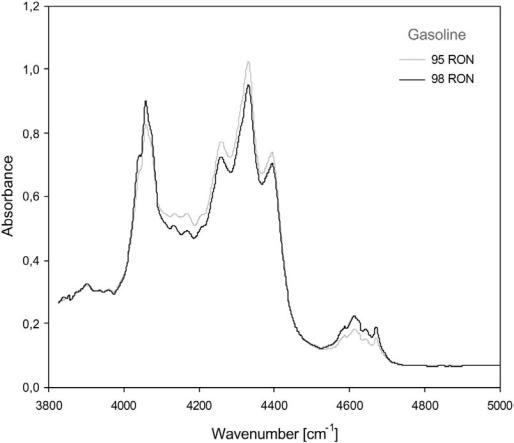
A fast and simple alternative to the previously described methods for octane number determination was proposed by BP[19] and involves the use of infrared (IR) spectroscopy. The near-IR region of the spectrum (wavelength: 800–2500 nm) contains many bands that result from overtones and combinations of carbon–hydrogen stretching vibrations, which are particularly useful for analyzing gasoline (Fig. 20). The variations in IR spectra can be coupled to a range of gasoline properties including RON and MON numbers. Automated and computerized instruments offer fast (1 min) analysis and have the possibility of
Figure 20 Near-IR absorbance spectra of two different gasolines.
Compositional Analysis of Naphtha and Reformate |
33 |
on-site sampling. The error of calculation is not significantly higher than for the composition–octane models derived from GC analysis.
REFERENCES
1.Speight, J.G. The Chemistry and Technology of Petroleum, 3rd Ed.; Chemical Industries Vol. 3; Marcel Dekker: New York, 1999.
2.http://www.statoil.com (Products and Services/Crude Oil and Condensate).
3.Parera, J.M.; Figoli, N.S. In Catalytic Naphtha Reforming, 1st Ed.; Chemical Industries Vol. 61; Marcel Dekker: New York, 1995.
4.Martino, G. Catalysis for oil refining and petrochemistry: recent developments and future trends. In Studies in Surface Science and Catalysis; Corma, A., Melo, F.V., Mendioroz, S., Fierro, J.L.G., Eds.; Proceedings of the 12th ICC, Granada, Spain, July 9–14, 2000; Vol. 130A; Elsevier: Amsterdam, 2000; 83–103.
5.Hartman, E.L.; Hanson, D.W.; Weber, B. Hydrocarbon Proc. 1998, 77.
6.http://www.paj.gr.jp/html/english/index.html (Petroleum Association of Japan, Annual Review 1999).
7.American Institute Research Project 45, 16th annual report, 1954.
8.Weast, Ed. Handbook of Chemistry and Physics, 58th ed.; CRC Press: Boca Raton, 1978.
9.Gjervan, T.; Prestvik, R.; Holmen, A. In Basic Principles of Applied Catalysis; Baerns, M., Ed.; in press.
10.Moljord, K.; Grande, K.; Tanem, I.; Holmen, A. In Deactivation and Testing of Hydrocarbon-Processing Catalysts; O’Connor, P., Takatsuka, T., Woolery, G.L., Eds.; ACS Symposium Series No. 634, 1995; 268–282.
11.Dietz, W.A. J. Gas Chromatogr. 1967, 5, 68.
12.Steiner, P.; Myrstad, R.; Thorvaldsen, B.; Blekkan, E., in preparation.
13.Benner, R.L.; Stedman, D.H. Anal. Chem. 1989, 61, 1268.
14.Adlard, E.R. Ed. Chromotography in the refining industry. J. Chromatogr. Lib., Vol. 56; Amsterdam, 1995.
15.Wauquier, J.-P. Ed. Petroleum Refining 1, Crude Oil, Petroleum Products, Process Flowsheets; IFP Publications, Editions Technip: Paris, 1994.
16.McCoy, R.D. ISA AID 73442, 187, 1973.
17.Anderson, P.C.; Sharkey, J.M.; Walsh, R.P. J. Inst. Petr. 1972, 58 (560), 83.
18.Durand, J.P.; Boscher, Y.; Petroff, N. J. Chromatrogr. 1987, 395, 229.
19.Descales, B.; Lambert, D.; Martens, A. Determination des nombres d’octane RON et MON des essences par la technique proche infrarouge, Revue de l’Association Francaise des Techniciens du Petrole, No 349, 1989.