

- •1.1 TODO LIST
- •2. PROGRAMMABLE LOGIC CONTROLLERS
- •2.1 INTRODUCTION
- •2.1.1 Ladder Logic
- •2.1.2 Programming
- •2.1.3 PLC Connections
- •2.1.4 Ladder Logic Inputs
- •2.1.5 Ladder Logic Outputs
- •2.2 A CASE STUDY
- •2.3 SUMMARY
- •2.4 PRACTICE PROBLEMS
- •2.5 PRACTICE PROBLEM SOLUTIONS
- •2.6 ASSIGNMENT PROBLEMS
- •3. PLC HARDWARE
- •3.1 INTRODUCTION
- •3.2 INPUTS AND OUTPUTS
- •3.2.1 Inputs
- •3.2.2 Output Modules
- •3.3 RELAYS
- •3.4 A CASE STUDY
- •3.5 ELECTRICAL WIRING DIAGRAMS
- •3.5.1 JIC Wiring Symbols
- •3.6 SUMMARY
- •3.7 PRACTICE PROBLEMS
- •3.8 PRACTICE PROBLEM SOLUTIONS
- •3.9 ASSIGNMENT PROBLEMS
- •4. LOGICAL SENSORS
- •4.1 INTRODUCTION
- •4.2 SENSOR WIRING
- •4.2.1 Switches
- •4.2.2 Transistor Transistor Logic (TTL)
- •4.2.3 Sinking/Sourcing
- •4.2.4 Solid State Relays
- •4.3 PRESENCE DETECTION
- •4.3.1 Contact Switches
- •4.3.2 Reed Switches
- •4.3.3 Optical (Photoelectric) Sensors
- •4.3.4 Capacitive Sensors
- •4.3.5 Inductive Sensors
- •4.3.6 Ultrasonic
- •4.3.7 Hall Effect
- •4.3.8 Fluid Flow
- •4.4 SUMMARY
- •4.5 PRACTICE PROBLEMS
- •4.6 PRACTICE PROBLEM SOLUTIONS
- •4.7 ASSIGNMENT PROBLEMS
- •5. LOGICAL ACTUATORS
- •5.1 INTRODUCTION
- •5.2 SOLENOIDS
- •5.3 VALVES
- •5.4 CYLINDERS
- •5.5 HYDRAULICS
- •5.6 PNEUMATICS
- •5.7 MOTORS
- •5.8 COMPUTERS
- •5.9 OTHERS
- •5.10 SUMMARY
- •5.11 PRACTICE PROBLEMS
- •5.12 PRACTICE PROBLEM SOLUTIONS
- •5.13 ASSIGNMENT PROBLEMS
- •6. BOOLEAN LOGIC DESIGN
- •6.1 INTRODUCTION
- •6.2 BOOLEAN ALGEBRA
- •6.3 LOGIC DESIGN
- •6.3.1 Boolean Algebra Techniques
- •6.4 COMMON LOGIC FORMS
- •6.4.1 Complex Gate Forms
- •6.4.2 Multiplexers
- •6.5 SIMPLE DESIGN CASES
- •6.5.1 Basic Logic Functions
- •6.5.2 Car Safety System
- •6.5.3 Motor Forward/Reverse
- •6.5.4 A Burglar Alarm
- •6.6 SUMMARY
- •6.7 PRACTICE PROBLEMS
- •6.8 PRACTICE PROBLEM SOLUTIONS
- •6.9 ASSIGNMENT PROBLEMS
- •7. KARNAUGH MAPS
- •7.1 INTRODUCTION
- •7.2 SUMMARY
- •7.3 PRACTICE PROBLEMS
- •7.4 PRACTICE PROBLEM SOLUTIONS
- •7.5 ASSIGNMENT PROBLEMS
- •8. PLC OPERATION
- •8.1 INTRODUCTION
- •8.2 OPERATION SEQUENCE
- •8.2.1 The Input and Output Scans
- •8.2.2 The Logic Scan
- •8.3 PLC STATUS
- •8.4 MEMORY TYPES
- •8.5 SOFTWARE BASED PLCS
- •8.6 SUMMARY
- •8.7 PRACTICE PROBLEMS
- •8.8 PRACTICE PROBLEM SOLUTIONS
- •8.9 ASSIGNMENT PROBLEMS
- •9. LATCHES, TIMERS, COUNTERS AND MORE
- •9.1 INTRODUCTION
- •9.2 LATCHES
- •9.3 TIMERS
- •9.4 COUNTERS
- •9.5 MASTER CONTROL RELAYS (MCRs)
- •9.6 INTERNAL RELAYS
- •9.7 DESIGN CASES
- •9.7.1 Basic Counters And Timers
- •9.7.2 More Timers And Counters
- •9.7.3 Deadman Switch
- •9.7.4 Conveyor
- •9.7.5 Accept/Reject Sorting
- •9.7.6 Shear Press
- •9.8 SUMMARY
- •9.9 PRACTICE PROBLEMS
- •9.10 PRACTICE PROBLEM SOLUTIONS
- •9.11 ASSIGNMENT PROBLEMS
- •10. STRUCTURED LOGIC DESIGN
- •10.1 INTRODUCTION
- •10.2 PROCESS SEQUENCE BITS
- •10.3 TIMING DIAGRAMS
- •10.4 DESIGN CASES
- •10.5 SUMMARY
- •10.6 PRACTICE PROBLEMS
- •10.7 PRACTICE PROBLEM SOLUTIONS
- •10.8 ASSIGNMENT PROBLEMS
- •11. FLOWCHART BASED DESIGN
- •11.1 INTRODUCTION
- •11.2 BLOCK LOGIC
- •11.3 SEQUENCE BITS
- •11.4 SUMMARY
- •11.5 PRACTICE PROBLEMS
- •11.6 PRACTICE PROBLEM SOLUTIONS
- •11.7 ASSIGNMENT PROBLEMS
- •12. STATE BASED DESIGN
- •12.1 INTRODUCTION
- •12.1.1 State Diagram Example
- •12.1.2 Conversion to Ladder Logic
- •12.1.2.1 - Block Logic Conversion
- •12.1.2.2 - State Equations
- •12.1.2.3 - State-Transition Equations
- •12.2 SUMMARY
- •12.3 PRACTICE PROBLEMS
- •12.4 PRACTICE PROBLEM SOLUTIONS
- •12.5 ASSIGNMENT PROBLEMS
- •13. NUMBERS AND DATA
- •13.1 INTRODUCTION
- •13.2 NUMERICAL VALUES
- •13.2.1 Binary
- •13.2.1.1 - Boolean Operations
- •13.2.1.2 - Binary Mathematics
- •13.2.2 Other Base Number Systems
- •13.2.3 BCD (Binary Coded Decimal)
- •13.3 DATA CHARACTERIZATION
- •13.3.1 ASCII (American Standard Code for Information Interchange)
- •13.3.2 Parity
- •13.3.3 Checksums
- •13.3.4 Gray Code
- •13.4 SUMMARY
- •13.5 PRACTICE PROBLEMS
- •13.6 PRACTICE PROBLEM SOLUTIONS
- •13.7 ASSIGNMENT PROBLEMS
- •14. PLC MEMORY
- •14.1 INTRODUCTION
- •14.2 MEMORY ADDRESSES
- •14.3 PROGRAM FILES
- •14.4 DATA FILES
- •14.4.1 User Bit Memory
- •14.4.2 Timer Counter Memory
- •14.4.3 PLC Status Bits (for PLC-5s and Micrologix)
- •14.4.4 User Function Control Memory
- •14.4.5 Integer Memory
- •14.4.6 Floating Point Memory
- •14.5 SUMMARY
- •14.6 PRACTICE PROBLEMS
- •14.7 PRACTICE PROBLEM SOLUTIONS
- •14.8 ASSIGNMENT PROBLEMS
- •15. LADDER LOGIC FUNCTIONS
- •15.1 INTRODUCTION
- •15.2 DATA HANDLING
- •15.2.1 Move Functions
- •15.2.2 Mathematical Functions
- •15.2.3 Conversions
- •15.2.4 Array Data Functions
- •15.2.4.1 - Statistics
- •15.2.4.2 - Block Operations
- •15.3 LOGICAL FUNCTIONS
- •15.3.1 Comparison of Values
- •15.3.2 Boolean Functions
- •15.4 DESIGN CASES
- •15.4.1 Simple Calculation
- •15.4.2 For-Next
- •15.4.3 Series Calculation
- •15.4.4 Flashing Lights
- •15.5 SUMMARY
- •15.6 PRACTICE PROBLEMS
- •15.7 PRACTICE PROBLEM SOLUTIONS
- •15.8 ASSIGNMENT PROBLEMS
- •16. ADVANCED LADDER LOGIC FUNCTIONS
- •16.1 INTRODUCTION
- •16.2 LIST FUNCTIONS
- •16.2.1 Shift Registers
- •16.2.2 Stacks
- •16.2.3 Sequencers
- •16.3 PROGRAM CONTROL
- •16.3.1 Branching and Looping
- •16.3.2 Fault Detection and Interrupts
- •16.4 INPUT AND OUTPUT FUNCTIONS
- •16.4.1 Immediate I/O Instructions
- •16.4.2 Block Transfer Functions
- •16.5 DESIGN TECHNIQUES
- •16.5.1 State Diagrams
- •16.6 DESIGN CASES
- •16.6.1 If-Then
- •16.6.2 Traffic Light
- •16.7 SUMMARY
- •16.8 PRACTICE PROBLEMS
- •16.9 PRACTICE PROBLEM SOLUTIONS
- •16.10 ASSIGNMENT PROBLEMS
- •17. OPEN CONTROLLERS
- •17.1 INTRODUCTION
- •17.3 OPEN ARCHITECTURE CONTROLLERS
- •17.4 SUMMARY
- •17.5 PRACTICE PROBLEMS
- •17.6 PRACTICE PROBLEM SOLUTIONS
- •17.7 ASSIGNMENT PROBLEMS
- •18. INSTRUCTION LIST PROGRAMMING
- •18.1 INTRODUCTION
- •18.2 THE IEC 61131 VERSION
- •18.3 THE ALLEN-BRADLEY VERSION
- •18.4 SUMMARY
- •18.5 PRACTICE PROBLEMS
- •18.6 PRACTICE PROBLEM SOLUTIONS
- •18.7 ASSIGNMENT PROBLEMS
- •19. STRUCTURED TEXT PROGRAMMING
- •19.1 INTRODUCTION
- •19.2 THE LANGUAGE
- •19.3 SUMMARY
- •19.4 PRACTICE PROBLEMS
- •19.5 PRACTICE PROBLEM SOLUTIONS
- •19.6 ASSIGNMENT PROBLEMS
- •20. SEQUENTIAL FUNCTION CHARTS
- •20.1 INTRODUCTION
- •20.2 A COMPARISON OF METHODS
- •20.3 SUMMARY
- •20.4 PRACTICE PROBLEMS
- •20.5 PRACTICE PROBLEM SOLUTIONS
- •20.6 ASSIGNMENT PROBLEMS
- •21. FUNCTION BLOCK PROGRAMMING
- •21.1 INTRODUCTION
- •21.2 CREATING FUNCTION BLOCKS
- •21.3 DESIGN CASE
- •21.4 SUMMARY
- •21.5 PRACTICE PROBLEMS
- •21.6 PRACTICE PROBLEM SOLUTIONS
- •21.7 ASSIGNMENT PROBLEMS
- •22. ANALOG INPUTS AND OUTPUTS
- •22.1 INTRODUCTION
- •22.2 ANALOG INPUTS
- •22.2.1 Analog Inputs With a PLC
- •22.3 ANALOG OUTPUTS
- •22.3.1 Analog Outputs With A PLC
- •22.3.2 Pulse Width Modulation (PWM) Outputs
- •22.3.3 Shielding
- •22.4 DESIGN CASES
- •22.4.1 Process Monitor
- •22.5 SUMMARY
- •22.6 PRACTICE PROBLEMS
- •22.7 PRACTICE PROBLEM SOLUTIONS
- •22.8 ASSIGNMENT PROBLEMS
- •23. CONTINUOUS SENSORS
- •23.1 INTRODUCTION
- •23.2 INDUSTRIAL SENSORS
- •23.2.1 Angular Displacement
- •23.2.1.1 - Potentiometers
- •23.2.2 Encoders
- •23.2.2.1 - Tachometers
- •23.2.3 Linear Position
- •23.2.3.1 - Potentiometers
- •23.2.3.2 - Linear Variable Differential Transformers (LVDT)
- •23.2.3.3 - Moire Fringes
- •23.2.3.4 - Accelerometers
- •23.2.4 Forces and Moments
- •23.2.4.1 - Strain Gages
- •23.2.4.2 - Piezoelectric
- •23.2.5 Liquids and Gases
- •23.2.5.1 - Pressure
- •23.2.5.2 - Venturi Valves
- •23.2.5.3 - Coriolis Flow Meter
- •23.2.5.4 - Magnetic Flow Meter
- •23.2.5.5 - Ultrasonic Flow Meter
- •23.2.5.6 - Vortex Flow Meter
- •23.2.5.7 - Positive Displacement Meters
- •23.2.5.8 - Pitot Tubes
- •23.2.6 Temperature
- •23.2.6.1 - Resistive Temperature Detectors (RTDs)
- •23.2.6.2 - Thermocouples
- •23.2.6.3 - Thermistors
- •23.2.6.4 - Other Sensors
- •23.2.7 Light
- •23.2.7.1 - Light Dependant Resistors (LDR)
- •23.2.8 Chemical
- •23.2.8.2 - Conductivity
- •23.2.9 Others
- •23.3 INPUT ISSUES
- •23.4 SENSOR GLOSSARY
- •23.5 SUMMARY
- •23.6 REFERENCES
- •23.7 PRACTICE PROBLEMS
- •23.8 PRACTICE PROBLEM SOLUTIONS
- •23.9 ASSIGNMENT PROBLEMS
- •24. CONTINUOUS ACTUATORS
- •24.1 INTRODUCTION
- •24.2 ELECTRIC MOTORS
- •24.2.1 Basic Brushed DC Motors
- •24.2.2 AC Motors
- •24.2.3 Brushless DC Motors
- •24.2.4 Stepper Motors
- •24.2.5 Wound Field Motors
- •24.3 HYDRAULICS
- •24.4 OTHER SYSTEMS
- •24.5 SUMMARY
- •24.6 PRACTICE PROBLEMS
- •24.7 PRACTICE PROBLEM SOLUTIONS
- •24.8 ASSIGNMENT PROBLEMS
- •25. CONTINUOUS CONTROL
- •25.1 INTRODUCTION
- •25.2 CONTROL OF LOGICAL ACTUATOR SYSTEMS
- •25.3 CONTROL OF CONTINUOUS ACTUATOR SYSTEMS
- •25.3.1 Block Diagrams
- •25.3.2 Feedback Control Systems
- •25.3.3 Proportional Controllers
- •25.3.4 PID Control Systems
- •25.4 DESIGN CASES
- •25.4.1 Oven Temperature Control
- •25.4.2 Water Tank Level Control
- •25.5 SUMMARY
- •25.6 PRACTICE PROBLEMS
- •25.7 PRACTICE PROBLEM SOLUTIONS
- •25.8 ASSIGNMENT PROBLEMS
- •26. FUZZY LOGIC
- •26.1 INTRODUCTION
- •26.2 COMMERCIAL CONTROLLERS
- •26.3 REFERENCES
- •26.4 SUMMARY
- •26.5 PRACTICE PROBLEMS
- •26.6 PRACTICE PROBLEM SOLUTIONS
- •26.7 ASSIGNMENT PROBLEMS
- •27. SERIAL COMMUNICATION
- •27.1 INTRODUCTION
- •27.2 SERIAL COMMUNICATIONS
- •27.2.1.1 - ASCII Functions
- •27.3 PARALLEL COMMUNICATIONS
- •27.4 DESIGN CASES
- •27.4.1 PLC Interface To a Robot
- •27.5 SUMMARY
- •27.6 PRACTICE PROBLEMS
- •27.7 PRACTICE PROBLEM SOLUTIONS
- •27.8 ASSIGNMENT PROBLEMS
- •28. NETWORKING
- •28.1 INTRODUCTION
- •28.1.1 Topology
- •28.1.2 OSI Network Model
- •28.1.3 Networking Hardware
- •28.1.4 Control Network Issues
- •28.2 NETWORK STANDARDS
- •28.2.1 Devicenet
- •28.2.2 CANbus
- •28.2.3 Controlnet
- •28.2.4 Ethernet
- •28.2.5 Profibus
- •28.2.6 Sercos
- •28.3 PROPRIETARY NETWORKS
- •28.3.1 Data Highway
- •28.4 NETWORK COMPARISONS
- •28.5 DESIGN CASES
- •28.5.1 Devicenet
- •28.6 SUMMARY
- •28.7 PRACTICE PROBLEMS
- •28.8 PRACTICE PROBLEM SOLUTIONS
- •28.9 ASSIGNMENT PROBLEMS
- •29. INTERNET
- •29.1 INTRODUCTION
- •29.1.1 Computer Addresses
- •29.1.2 Phone Lines
- •29.1.3 Mail Transfer Protocols
- •29.1.4 FTP - File Transfer Protocol
- •29.1.5 HTTP - Hypertext Transfer Protocol
- •29.1.6 Novell
- •29.1.7 Security
- •29.1.7.1 - Firewall
- •29.1.7.2 - IP Masquerading
- •29.1.8 HTML - Hyper Text Markup Language
- •29.1.9 URLs
- •29.1.10 Encryption
- •29.1.11 Compression
- •29.1.12 Clients and Servers
- •29.1.13 Java
- •29.1.14 Javascript
- •29.1.16 ActiveX
- •29.1.17 Graphics
- •29.2 DESIGN CASES
- •29.2.1 Remote Monitoring System
- •29.3 SUMMARY
- •29.4 PRACTICE PROBLEMS
- •29.5 PRACTICE PROBLEM SOLUTIONS
- •29.6 ASSIGNMENT PROBLEMS
- •30. HUMAN MACHINE INTERFACES (HMI)
- •30.1 INTRODUCTION
- •30.2 HMI/MMI DESIGN
- •30.3 DESIGN CASES
- •30.4 SUMMARY
- •30.5 PRACTICE PROBLEMS
- •30.6 PRACTICE PROBLEM SOLUTIONS
- •30.7 ASSIGNMENT PROBLEMS
- •31. ELECTRICAL DESIGN AND CONSTRUCTION
- •31.1 INTRODUCTION
- •31.2 ELECTRICAL WIRING DIAGRAMS
- •31.2.1 Selecting Voltages
- •31.2.2 Grounding
- •31.2.3 Wiring
- •31.2.4 Suppressors
- •31.2.5 PLC Enclosures
- •31.2.6 Wire and Cable Grouping
- •31.3 FAIL-SAFE DESIGN
- •31.4 SAFETY RULES SUMMARY
- •31.5 REFERENCES
- •31.6 SUMMARY
- •31.7 PRACTICE PROBLEMS
- •31.8 PRACTICE PROBLEM SOLUTIONS
- •31.9 ASSIGNMENT PROBLEMS
- •32. SOFTWARE ENGINEERING
- •32.1 INTRODUCTION
- •32.1.1 Fail Safe Design
- •32.2 DEBUGGING
- •32.2.1 Troubleshooting
- •32.2.2 Forcing
- •32.3 PROCESS MODELLING
- •32.4 PROGRAMMING FOR LARGE SYSTEMS
- •32.4.1 Developing a Program Structure
- •32.4.2 Program Verification and Simulation
- •32.5 DOCUMENTATION
- •32.6 COMMISIONING
- •32.7 REFERENCES
- •32.8 SUMMARY
- •32.9 PRACTICE PROBLEMS
- •32.10 PRACTICE PROBLEM SOLUTIONS
- •32.11 ASSIGNMENT PROBLEMS
- •33. SELECTING A PLC
- •33.1 INTRODUCTION
- •33.2 SPECIAL I/O MODULES
- •33.3 SUMMARY
- •33.4 PRACTICE PROBLEMS
- •33.5 PRACTICE PROBLEM SOLUTIONS
- •33.6 ASSIGNMENT PROBLEMS
- •34. FUNCTION REFERENCE
- •34.1 FUNCTION DESCRIPTIONS
- •34.1.1 General Functions
- •34.1.2 Program Control
- •34.1.3 Timers and Counters
- •34.1.4 Compare
- •34.1.5 Calculation and Conversion
- •34.1.6 Logical
- •34.1.7 Move
- •34.1.8 File
- •34.1.10 Program Control
- •34.1.11 Advanced Input/Output
- •34.1.12 String
- •34.2 DATA TYPES
- •35. COMBINED GLOSSARY OF TERMS
- •36. PLC REFERENCES
- •36.1 SUPPLIERS
- •36.2 PROFESSIONAL INTEREST GROUPS
- •36.3 PLC/DISCRETE CONTROL REFERENCES
- •37. GNU Free Documentation License
- •37.1 PREAMBLE
- •37.2 APPLICABILITY AND DEFINITIONS
- •37.3 VERBATIM COPYING
- •37.4 COPYING IN QUANTITY
- •37.5 MODIFICATIONS
- •37.6 COMBINING DOCUMENTS
- •37.7 COLLECTIONS OF DOCUMENTS
- •37.8 AGGREGATION WITH INDEPENDENT WORKS
- •37.9 TRANSLATION
- •37.10 TERMINATION
- •37.11 FUTURE REVISIONS OF THIS LICENSE
- •37.12 How to use this License for your documents
plc electrical - 31.12
When designing and building electrical control systems, the following points should prove useful.
•Avoid ground loops
-Connect the enclosure to the ground bus.
-Each PLC component should be grounded back to the main PLC chassis. The PLC chassis should be grounded to the backplate.
-The ground wire should be separated from power wiring inside enclosures.
-Connect the machine ground to the enclosure ground.
•Ensure good electrical connection
-Use star washers to ensure good electrical connection.
-Mount ground wires on bare metal, remove paint if needed.
-Use 12AWG stranded copper for PLC equipment grounds and 8AWG stranded copper for enclosure backplate grounds.
-The ground connection should have little resistance (<0.1 ohms is good).
31.2.3Wiring
As the amount of current carried by a wire increases, it is important to use a wire with a larger cross section. A larger cross section results in a lower resistance, and less heating of the wire. The standard wire gages are listed in Figure 31.10.
AWG # |
Dia. (mil) |
Res. 25C |
Rated Current |
|
|
(ohm/1000 ft) |
(A) |
|
|
|
|
4 |
204 |
0.25 |
|
6 |
162 |
0.40 |
|
8 |
128 |
0.64 |
|
10 |
102 |
1.0 |
|
12 |
81 |
1.6 |
|
14 |
64 |
2.6 |
|
16 |
51 |
4.1 |
|
18 |
40 |
6.5 |
|
20 |
32 |
10 |
|
22 |
25 |
17 |
|
24 |
20 |
26 |
|
|
|
|
|
Figure 31.10 American Wire Gage (AWG) Copper Wire Sizes
plc electrical - 31.13
31.2.4 Suppressors
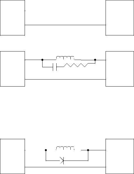
Most of us have seen a Vandegraaf generator, or some other inductive device that can generate large sparks using inductive coils. On the factory floor there are some massive inductive loads that make this a significant design problem. This includes devices such as large motors and inductive furnaces. The root of the problem is that coils of wire act as inductors and when current is applied they build up magnetic fields, requiring energy. When the applied voltage is removed and the fields collapse the energy is dumped back out into the electrical system. As a result, when an inductive load is turned on it draws an excess amount of current (and lights dim), and when it is turn it off there is a power surge. In practical terms this means that large inductive loads will create voltage spikes that will damage our equipment.
Surge suppressors can be used to protect equipment from voltage spikes caused by inductive loads. Figure 31.11 shows the schematic equivalent of an uncompensated inductive load. For this to work reliably we would need to over design the system above the rated loads. The second schematic shows a technique for compensating for an AC inductive load using a resistor capacitor pair. It effectively acts as a high pass filter that allows a high frequency voltage spike to be short circuited. The final surge suppressor is common for DC loads. The diode allows current to flow from the negative to the positive. If a negative voltage spike is encountered it will short circuit through the diode.
plc electrical - 31.14
inductive load
output 
 VDC+/VAC
Uncompensated
VDC-/COM.
common
Control Relay (PLC) |
Power supply |
|
inductive load |
|
output |
L |
VAC |
|
||
|
|
+ |
C |
R |
Vs |
|
|
- |
common |
|
COM. |
|
|
|
Relay or Triac |
|
Power supply |
R = Vs*(.5 to 1) ohms
C = (.5 to 1)/Adc (microfarads)
Vcapacitor = 2(Vswitching) + (200 to 300) V
Compensating for AC loads
|
where, |
Adc is the rated amperage of the load |
|
|
|
|
|
|
|
Vs is the voltage of the load/power supply |
|
|
|
Vswitching may be up to 10*Vs |
|
|
|
inductive load |
|
output |
|
+ |
Compensating |
|
|
|
for DC loads |
common |
|
- |
|
|
|
|
|
Relay or Transistor |
|
Power supply |
|
Figure 31.11 Surge Suppressors
31.2.5 PLC Enclosures
PLCs are well built and rugged, but they are still relatively easy to damage on the factory floor. As a result, enclosures are often used to protect them from the local environment. Some of the most important factors are listed below with short explanations.
plc electrical - 31.15
Dirt - Dust and grime can enter the PLC through air ventilation ducts. As dirt clogs internal circuitry, and external circuitry, it can effect operation. A storage cabinet such as Nema 4 or 12 can help protect the PLC.
Humidity - Humidity is not a problem with many modern materials. But, if the humidity condenses, the water can cause corrosion, conduct current, etc. Condensation should be avoided at all costs.
Temperature - The semiconductor chips in the PLC have operating ranges where they are operational. As the temperature is moved out of this range, they will not operate properly, and the PLC will shut down. Ambient heat generated in the PLC will help keep the PLC operational at lower temperatures (generally to 0°C). The upper range for the devices is about 60°C, which is generally sufficient for sealed cabinets, but warm temperatures, or other heat sources (e.g. direct irradiation from the sun) can raise the temperature above acceptable limits. In extreme conditions heating, or cooling units may be required. (This includes “cold-starts” for PLCs before their semiconductors heat up).
Shock and Vibration - The nature of most industrial equipment is to apply energy to change workpieces. As this energy is applied, shocks and vibrations are often produced. Both will travel through solid materials with ease. While PLCs are designed to withstand a great deal of shock and vibration, special elastomer/ spring or other mounting equipment may be required. Also note that careful consideration of vibration is also required when wiring.
Interference - Electromagnetic fields from other sources can induce currents. Power - Power will fluctuate in the factory as large equipment is turned on and off.
To avoid this, various options are available. Use an isolation transformer. A UPS (Uninterruptable Power Supply) is also becoming an inexpensive option, and are widely available for personal computers.
A standard set of enclosures was developed by NEMA (National Electric Manufacturers Association). These enclosures are intended for voltage ratings below 1000Vac. Figure 31.12 shows some of the rated cabinets. Type 12 enclosures are a common choice for factory floor applications.