

Chapter 1
Introduction
This chapter introduces the ARM PrimeCell Color LCD Controller (PL110) and contains the following section:
•About the ARM PrimeCell Color LCD Controller (PL110) on page 1-2.
ARM DDI 0161D |
Copyright © ARM Limited 1999, 2000. All rights reserved. |
1-1 |

Introduction
1.1About the ARM PrimeCell Color LCD Controller (PL110)
The ARM PrimeCell Color Liquid Crystal Display Controller (CLCDC) is an Advanced Microcontroller Bus Architecture (AMBA) master-slave module that connects to the Advanced High-performance Bus (AHB). The PrimeCell CLCDC is an AMBA-compliant System-on-a-Chip (SoC) peripheral that is developed, tested and licensed by ARM.
The PrimeCell CLCDC is a reusable soft-IP block that has been developed with the prime aim of reducing time-to-market for ASIC development.
The PrimeCell CLCDC provides all the necessary control signals to interface directly to a variety of color and monochrome LCD panels.
1.1.1Features of the PrimeCell Color LCD Controller
The principal features of the PrimeCell CLCDC are:
•compliance to the AMBA Specification (Rev 2.0) onwards for easy integration into SoC implementation
•dual 16-deep programmable 32-bit wide FIFOs for buffering incoming display data
•supports single and dual panel mono Super Twisted Nematic (STN) displays with 4 or 8-bit interfaces
•supports single and dual-panel color and monochrome STN displays
•supports Thin Film Transistor (TFT) color displays
•resolution programmable up to 1024 x 768
•15 gray-level mono, 3375 color STN, and 32K color TFT support
•1, 2 or 4 bits-per-pixel (bpp) palettized displays for mono STN
•1, 2, 4 or 8 bpp palettized color displays for color STN and TFT
•16 bpp true-color non-palettized, for color STN and TFT
•24 bpp true-color non-palettized, for color TFT
•programmable timing for different display panels
•256 entry, 16-bit palette RAM, arranged as a 128 x 32-bit RAM physically
•frame, line and pixel clock signals
•AC bias signal for STN, data enable signal for TFT panels
•patented gray-scale algorithm
•supports little and big-endian, as well as WinCE data formats.
1-2 |
Copyright © ARM Limited 1999, 2000. All rights reserved. |
ARM DDI 0161D |

Introduction
1.1.2Programmable parameters
The following key parameters can be programmed:
•horizontal front and back porch
•horizontal synchronization pulse width
•number of pixels per line
•vertical front and back porch
•vertical synchronization pulse width
•number of lines per panel
•number of panel clocks per line
•signal polarity, active HIGH or LOW
•AC panel bias
•panel clock frequency
•bits-per-pixel
•display type, STN mono/color or TFT
•STN 4 or 8-bit interface mode
•STN dual or single panel mode
•little-endian, big-endian or WinCE mode
•interrupt generation event.
1.1.3Target markets
The markets to which the PrimeCell CLCDC is addressed are primarily in the portable segment. Typical applications for the PrimeCell CLCDC include:
•Personal Digital Assistant (PDA)
•ultra-sub notebook computer
•smart-phone
•hand-held, portable color games terminal.
1.1.4LCD panel resolution
The PrimeCell CLCDC can be programmed to support a wide range of panel resolutions such as:
•320 x 200, 320 x 240
•640 x 200, 640 x 240, 640 x 480
•800 x 600
•1024 x 768.
ARM DDI 0161D |
Copyright © ARM Limited 1999, 2000. All rights reserved. |
1-3 |

Introduction
1.1.5Types of LCD panel supported
The PrimeCell CLCDC supports the following types of LCD panel:
•active matrix TFT panels with up to 24-bit bus interface
•single-panel monochrome STN panels (4-bit and 8-bit bus interface)
•dual-panel monochrome STN panels (4-bit and 8-bit bus interface per panel)
•single-panel color STN panels, 8-bit bus interface
•dual-panel color STN panels, 8-bit bus interface per panel.
1.1.6Number of colors supported
The number of colors supported by the different types of panels are described in:
•TFT panels
•Color STN panels
•Mono STN panels on page 1-5.
TFT panels
TFT panels support one or more of the following color modes:
•1 bpp, palettized, 2 colors selected from available colors.
•2 bpp, palettized, 4 colors selected from available colors.
•4 bpp, palettized, 16 colors selected from available colors.
•8 bpp, palettized, 256 colors selected from available colors.
•16 bpp, direct 5:5:5 RGB, with one bpp not normally being used. This pixel is still output, and can be used as a bright bit to connect to the Least Significant Bit (LSB) of R, G and B components of a 6:6:6 TFT panel.
•24 bpp, direct 8:8:8 RGB, providing over 16 million colors.
Each 16-bit palette entry is composed of five bpp (RGB) plus a common intensity bit. This gives better memory utilization and performance compared with a full six bpp structure. The total amount of colors supported can be doubled from 32K to 64K if the intensity bit is used and applied to all three color components simultaneously. Refer to Appendix A ARM PrimeCell Color LCD Controller (PL110) Signal Descriptions for more information.
Color STN panels
Color STN panels support one or more of the following color modes:
•1 bpp, palettized, 2 colors selected from 3375
•2 bpp, palettized, 4 colors selected from 3375
•4 bpp, palettized, 16 colors selected from 3375
1-4 |
Copyright © ARM Limited 1999, 2000. All rights reserved. |
ARM DDI 0161D |

Introduction
•8 bpp, palettized, 256 colors selected from 3375
•16 bpp, direct 4:4:4 RGB, with 4 bpp not being used.
Mono STN panels
Mono STN panels support one or more of the following modes:
•1 bpp, palettized, 2 gray scales selected from 15
•2 bpp, palettized, 4 gray scales selected from 15
•4 bpp, palettized, 16 gray scales selected from 15.
Greater than four bpp for mono panels can be programmed, but using these modes does not make sense, since the maximum number of gray scales supported on the display is 15.
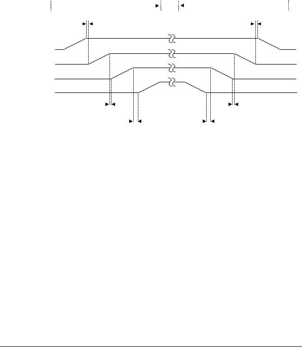
1.1.7LCD powering up and powering down sequence support
The PrimeCell CLCDC (PL110) allows the following power up sequence to be performed:
1.Vdd is simultaneously applied to the SoC (that contains the PrimeCell CLCDC PL110 peripheral) and panel display driver logic. The signals CLLP, CLCP, CLFP, CLAC, CLD[23:0] and CLLE are held LOW (inactive).
2.When Vdd is stabilized, a 1 is written to the LcdEn bit within the LCDControl Register. This enables the signals CLLP, CLCP, CLFP, CLAC and CLLE into their active states, but the CLD[23:0] signals remain in a LOW (inactive) state.
3.When the signals in (2) have stabilized, where appropriate, the contrast voltage VEE (this is not controlled or supplied by the PrimeCell CLCDC) is then applied.
4.If required, a software timer routine, can be used to provide the minimum display specific delay time between application of the control signals and power to the panel display. On completion of the software timer routine, power is applied to the panel by writing a 1 to the LcdPwr bit within the LcdControl register, which in turn, sets the CLPOWER signal HIGH and enables the CLD[23:0] signals into their active state. The CLPOWER signal is expected to be used to gate the power to the LCD panel.
The power down sequence is the reverse of the above four stages and must be strictly followed, this time, writing the respective register bits with 0.
The power up and power down sequences are shown in Figure 1-1 on page 1-6.
ARM DDI 0161D |
Copyright © ARM Limited 1999, 2000. All rights reserved. |
1-5 |
Introduction
|
|
LCD on sequence |
|
LCD off sequence |
||||||
|
|
|
|
|
|
|||||
Min. 0ms |
|
|
|
|
Min. 0ms |
|||||
|
|
|
|
|
|
|
|
|
|
|
SoC, PL110
Vdd
CLLP, CLCP, CLFP,
CLAC, CLLE
Vee
CLPOWER,
CLD[23:0]
Min. 0ms |
|
|
|
|
|
|
|
Min. 0ms |
||||||
|
|
|
|
|
|
|
|
|
|
|
|
|
|
|
Min. (display specific) ms |
|
|
|
|
|
|
|
Min. (display specific) ms |
||||||
(provided through software) |
|
|
|
|
(provided through software) |
|||||||||
|
|
|
|
|
|
|
Figure 1-1 Power up and power down sequences |
|||||||
1-6 |
Copyright © ARM Limited 1999, 2000. All rights reserved. |
ARM DDI 0161D |