


Permissible Cable Lengths and Nodes Per Segment
Transceiver Description |
Cable |
Connectors |
Cable Length |
Max Nodes |
Notes |
|
|
|
|
Min |
Max |
Bus Segment |
|
coaxial star |
RG-62/u |
BNC |
0 |
2000ft/610m |
N/A |
5.5 dB/1000ft max |
coaxial star |
RG-59/u |
BNC |
0 |
1500ft/457m |
N/A |
7.0 dB/1000ft max |
coaxial bus |
RG-62/u |
BNC |
6ft/2m1 |
1000ft/305m |
8 |
5.5 dB/1000ft max |
duplex fiber optic (850 nm) |
50/125 |
SMA or ST |
0 |
3000ft/915m |
N/A |
4.3 dB/km max |
duplex fiber optic (850 nm) |
62.5/125 |
SMA or ST |
0 |
6000ft/1825m |
N/A |
4.3 dB/km max |
duplex fiber optic (850 nm) |
100/140 |
SMA or ST |
02 |
9000ft/2740m |
N/A |
4.0 dB/km max |
duplex fiber optic (1300 nm) |
single mode |
ST |
0 |
46000ft/14000m |
N/A |
0.5 dB/km max |
duplex fiber optic (1300 nm) |
50/125 |
ST |
02 |
32800ft/10000m |
N/A |
1.5 dB/km max |
duplex fiber optic (1300 nm) |
62.5/125 |
ST |
02 |
35000ft/10670m |
N/A |
1.5 dB/km max |
twisted-pair star |
IBM type 3 |
RJ-11 |
0 |
330ft/100m |
N/A |
uses internal BALUNs |
twisted-pair bus |
IBM type 3 |
RJ-11, screw |
6ft/2m1 |
400ft/122m |
8 |
|
DC coupled EIA-485 |
IBM type 3 |
RJ-11, screw |
0 |
900ft/274m |
17 |
DC coupled |
AC coupled EIA-485 |
IBM type 3 |
RJ-11, screw |
0 |
700ft/213m |
13 |
transformer isolated |
1 This represents the minimum distance between any two nodes or between a node and a hub.
2 May require a jumper change to achieve this distance.
Data Link Layer Local Area Network: Token Bus (2.5 Mbps) and copies are available from the ATA office. ARCNET is properly classified as a token bus technology since a token is the primary means of mediating access to the cable. It operates under the source/destination model since the destination of the message must be identified during a transmission. The term bus implies that each ARCNET node is capable of monitoring all the traffic on the network regardless of destination. This is important when the network is being reconfigured or the detection of a lost token is to be determined. Even when hubs are being used, it is important that all nodes on the network are capable of monitoring all the traffic on the network in order for ARCNET’s data link layer to function properly.
Conventional ARCNET operates at 2.5 Mbps and much of the timing information presented assumes that speed. At this speed, a signal element on the medium must occur within 400 ns. For a logic 1 the symbol is a dipulse. For a logic 0 there is the absence of a dipulse. Putting symbols together creates basic symbol units.
Basic Symbol Units
Basic symbol units are the elements used to construct basic frames and reconfiguration bursts.
<SD>— Starting Delimiter
1 1 1 1 1 1 (6 symbols)
All ARCNET frames begin with six logic 1s.
This is referred to as the Alert Burst.
<RSU>—Reconfiguration Symbol Unit
1 1 1 1 1 1 1 1 0 (9 symbols)
18
www.ccontrols.com

<ISU>—Information Symbol Unit
1 1 0 d0 d1 d2 d3 d4 d5 d6 d7 |
(11 symbols) |
Each information unit contains 8 bits of data and a 3-bit preamble 1 1 0. The definition and value of the data are as follows:
<SOH>—Start of Header 0x01
Used to identify a packet
<ENQ>—Enquiry 0x85
Used to identify a request for a free buffer
<ACK>—Acknowledgement 0x86
Used to identify acceptance
<NAK>—Negative Acknowledgement 0x15
Used to identify non-acceptance
<EOT>—End of Transmission 0x04
Used to identify a token pass to the logical neighbor.
<NID>—Next Node Identification 0x01 to 0xFF
Used to identify the next node in the token loop. The NID is the logical neighbor of the node with the token.
<SID>—Source Node Identification 0x01 to 0xFF
Used to identify the source node of a packet transmission.
<DID>—Destination Node Identification 0x00 to 0xFF
Used to identify the destination node of a transmission request or a packet transmission.
<CP>—Continuation Pointer 0x03 to 0xFF
Used to identify the length of packet. In short packet mode (0 to 252 bytes), the CP requires only one ISU. In long packet mode (256 to 507 bytes), the CP requires two ISUs.
<SC>—System Code 0x00 to 0XFF
Used to identify a high level protocol. System codes generally require one ISU but two ISU system codes exist. System codes have been assigned by Datapoint Corporation. The ARCNET Trade Association has a list of system code assignments.
<…DATA…>—Data
Contains the user data. The number of ISUs can range from 0 to 252 in short packet mode and 256 to 507 in long packet mode. Packets which contain 253, 254 or 255 ISUs cannot be sent. Packets of this size are called exception packets and must be padded with null data and sent as a long packet.
<FCS>—Frame Check Sequence 0x00 to 0xFFFF
Contains the appended cyclic redundancy check (CRC-16) for the packet sent. Two ISUs are required.
19
www.ccontrols.com
Invitation to Transmit (ITT)
SD |
6 bits = |
2.4 |
|
µs |
|
EOT |
11 bits = |
4.4 |
|
|
|
NID |
11 bits = |
4.4 |
|
|
|
NID |
11 bits = |
4.4 |
|
|
|
|
|
15.6 |
|
µs |
|
|
|
|
|
|
|
Free Buffer Enquiry (FBE) |
|
|
|
|
|
SD |
6 bits = |
2.4 |
|
µs |
|
ENQ |
11 bits = 4.4 |
|
|
|
|
DID |
11 bits = |
4.4 |
|
|
|
DID |
11 bits = |
4.4 |
|
|
|
|
|
15.6 |
|
µs |
|
|
|
|
|
|
|
Acknowledgment (ACK) |
|
|
|
|
|
SD |
6 bits = |
2.4 |
|
µs |
|
ACK |
11 bits = |
4.4 |
|
|
|
|
|
6.8 |
|
µs |
|
|
|
|
|
|
|
Negative Acknowledgment (NAK) |
|
|
|
|
|
SD |
6 bits = |
2.4 |
|
µs |
|
NAK |
11 bits = |
4.4 |
|
|
|
|
|
6.8 |
|
µs |
|
|
|
|
|
|
|
Short Packet (PAC) |
|
|
|
|
|
SD |
6 bits = |
2.4 |
|
µs |
|
SOH |
11 bits = |
4.4 |
|
|
|
SID |
11 bits = |
4.4 |
|
|
|
DID |
11 bits = |
4.4 |
|
|
|
DID |
11 bits = |
4.4 |
|
|
|
CP |
11 bits = |
4.4 |
|
|
|
SC |
11 bits = |
4.4 |
|
|
|
*n Characters |
nx11 bits = |
4.4 n |
|
|
|
FCS |
22 bits = |
8.8 |
|
|
|
|
|
37.6 |
|
|
|
|
+ 4.4 n |
µs |
|
||
*1 less than the number of bytes following CP |
|
|
|
|
|
|
|
|
|
|
|
Long Packet (PAC) |
|
|
|
|
|
SD |
6 bits = |
2.4 |
|
µs |
|
SOH |
11 bits = |
4.4 |
|
|
|
SID |
11 bits = |
4.4 |
|
|
|
DID |
11 bits = |
4.4 |
|
|
|
DID |
11 bits = |
4.4 |
|
|
|
CP |
22 bits = |
8.8 |
|
|
|
SC |
11 bits = |
4.4 |
|
|
|
*n Characters |
nx11 bits = |
4.4 |
n |
|
|
FCS |
22 bits = |
8.8 |
|
|
|
|
|
42.0 |
|
|
|
|
+ 4.4 n |
µs |
|
||
*1 less than the number of bytes following CP
Frame Format
There are two frame formats with ARCNET. The basic frame format provides control and information between the nodes while the reconfiguration burst is unique to the reconfiguration process. Frames are constructed by putting together basic symbol units.
Basic Frames
There are only five basic frames in the ARCNET data link layer protocol. The five basic frames are as follows:
IIT—Invitation to Transmit (token) <SD><EOT><NID><NID>
FBE—Free Buffer Enquiry
<SD><ENQ><DID><DID>
ACK—Acknowledgement
<SD><ACK>
NAK—Negative Acknowledgement
<SD><NAK>
PAC—Packet
<SD><SOH><SID><DID><DID><CP><SC><…DATA…><FCS>
There are a few things to notice with these five frames. When passing the token, the NID is sent twice. Likewise, the DID is sent twice when requesting a transmission or sending a packet. The source of an ACK or NAK is not identified. It is implied to come from the destination node. The only time the source node is identified is during a packet transmission. It is not sent during an FBE. It is implied that an FBE comes from the source node.
System Codes
The byte immediately following the continuation pointer in every ARCNET packet must be a system code that acts as a protocol identifier. This allows a number of protocols using independent message formats to coexist on a single physical network. Every packet must have a system code even if no nodes support multiple protocols to allow more than one node type on the network.
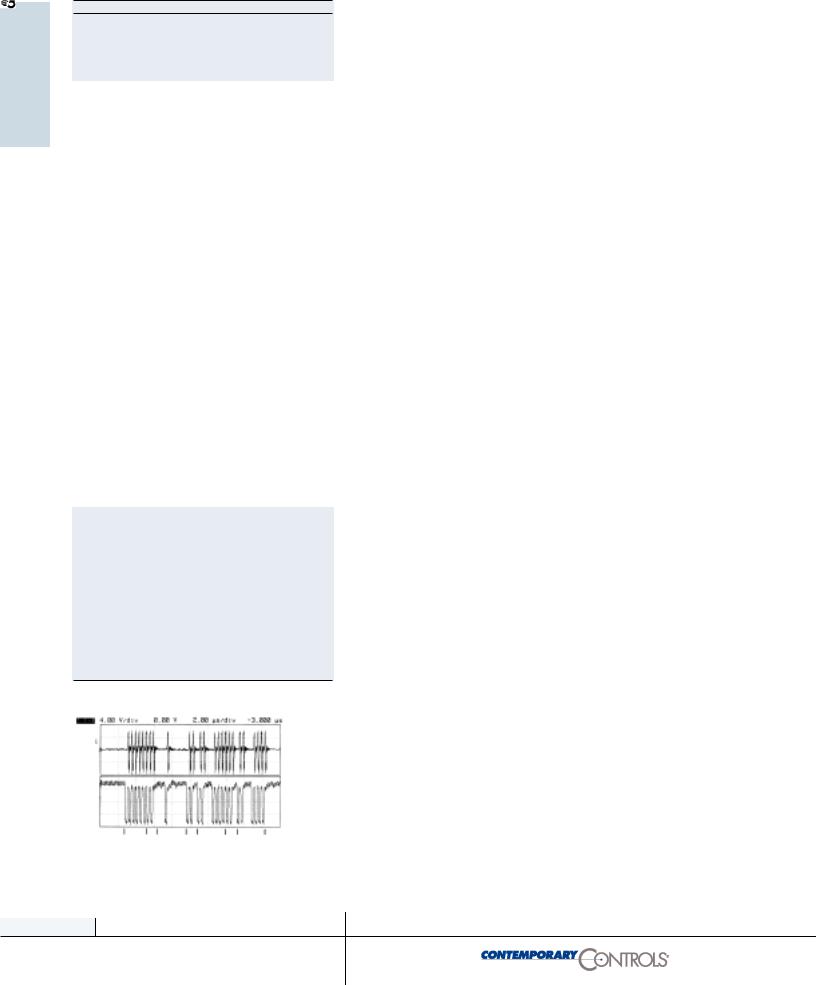
4.00 V/div |
|
0.00 V |
|
2.00 µs/div |
|
-3.000 µs |
1:
Dipulse on
Cable
2:
Tx
System code 0x80 is reserved for general-purpose diagnostic use. Any node can send a packet with system code 80 at any time. Any node receiving a packet with system code 80 ignores the packet.
System codes for different operating systems and manufacturers have been assigned by Datapoint Corporation.
20
www.ccontrols.com
Deterministic Transmission
Times
Reconfiguration Burst
The reconfiguration burst is a special frame only used in the reconfiguration process. It is a jam signal of sufficient length to destroy any activity occurring on the network ensuring that all nodes are aware that a reconfiguration of the network will take place.
RECON—Reconfiguration Burst
<RSU><RSU>…<RSU> 765 RSUs
Delay Constants
Token pass
ITT |
15.6 |
µs |
|
|
Tta |
12.6 |
|
+ |
Tpt |
|
28.2 |
µs |
+ |
Tpt |
Token pass and short packet of n data bytes (successfully delivered)
ITT |
15.6 |
µs |
|
Tta |
12.6 |
+ |
Tpt |
FBE |
15.6 |
|
|
Tta |
12.6 |
+ |
Tpm |
ACK |
6.8 |
|
|
Tta |
12.6 |
+ |
Tpm |
PAC |
37.6 |
+ |
4.4n |
Tta |
12.6 |
+ |
Tpm |
ACK |
6.8 |
|
|
Tta |
12.6 |
+ |
Tpm |
|
145.4 |
µs |
|
|
|
|
|
|
|
|
|
|
|
|
|
|
|
|
|
|
|
|
|
Since ARCNET uses a token passing means to arbitrate station access to the medium, the time it takes to transmit messages is predictable. In order to make these calculations, it is necessary to understand certain delays inherent in the ARCNET controller and the cable used to interconnect the various stations. The delays due to the ARCNET controller are scalable to the data rate used. The delays at 5 Mbps are half as much as the delays at 2.5 Mbps. The delays due to cabling are not scalable. What follows are the delays for conventional ARCNET operating at 2.5 Mbps.
Tta—Turnaround Time
The ARCNET controller chip has a response time of about 12.6µs. This is the time between the end of a received transmission and the start of a response to that transmission.
Tpt—Medium Propagation, Token Pass to Logical Neighbor
The medium propagation time is the time it takes for the transmission of a symbol from one point to the receipt of the same symbol at another point. The medium propagation constant varies with the type of media used. In the case of coaxial cable use 4 ns/m; for fiber optics use 5 ns/m; and for twisted-pair use 5.5 ns/m. Therefore the length of the medium between transmitter and receiver must be known or approximated for calculation purposes. Sometimes an average length is used to simplify calculations. The parameter Tpt refers to the time it takes for a symbol to travel from the node with the token to its logical neighbor. For standard timeouts Tpt should not exceed 31µs. Remember that this is the one way propagation time.
Tpm—Medium Propagation, Source Node to Destination Node
Since transmissions can occur between any two nodes, the time it takes for a symbol to travel from the source of the transmission to the destination must be known. Use the same propagation constants as above but determine the distance between the source
21
www.ccontrols.com

Token pass and short packet of n data bytes (broadcast)
ITT |
15.6 |
µs |
|
Tta |
12.6 |
+ |
Tpt |
PAC |
37.6 |
+ |
4.4n |
Tbd |
15.6 |
|
|
|
81.4 |
µs |
|
|
|
+ |
4.4n |
|
|
+ |
Tpt |
Token pass and short packet of n data bytes (lost ACK)
ITT |
15.6 |
µs |
|
Tta |
12.6 |
+ |
Tpt |
FBE |
15.6 |
|
|
Tta |
12.6 |
+ |
Tpm |
ACK |
6.8 |
|
|
Tta |
12.6 |
+ |
Tpm |
PAC |
37.6 |
+ |
4.4n |
Trp |
75.6 |
|
|
Trc |
2.0 |
|
|
|
191.0 |
µs |
|
|
|
+ |
4.4n |
|
|
+ |
Tpt |
|
|
|
2Tpm |
Token pass and packet (inactive destination)
ITT |
15.6 |
µs |
|
Tta |
12.6 |
+ |
Tpt |
FBE |
15.6 |
|
|
Trp |
75.6 |
|
|
Trc |
2.0 |
|
|
|
121.4 |
µs |
|
|
|
+ |
Tpt |
Token pass and packet (no response)
ITT |
15.6 |
µs |
Trp |
75.6 |
|
Trc |
2.0 |
|
|
93.2 |
µs |
node and the destination node. For standard timeouts, Tpm should not exceed 31µs.
Tpd—Broadcast Delay Time
Broadcast delay time is the time that elapses from the end of a transmitted broadcast packet until the start of a token pass. At standard timeouts this time is about 15.6µs.
Trp—Response Timeout
Response timeout is the maximum time a transmitting node will wait for a response. It is approximately equal to two times the maximum medium propagation delay of 31µs plus the turnaround delay of the ARCNET controller chip. If the response time is exceeded, the transmitting node will assume the destination node is not on the network. The response timeout is about 75.6µs and it scales with extended timeouts.
Trc—Recovery Time
This is the time that elapses from the end of a response timeout until the start of a token pass. Trc is about 2µs.
Tac—Timer Activity Timeout
The timer activity timeout represents the maximum amount of time that the network can experience no activity. If this time is exceeded, a reconfiguration sequence is initiated. The Tac is approximately 82.4µs.
Calculating Transaction Times
With a knowledge of delay constants and the times required to send different ARCNET frames, calculating transaction times for various transmissions is possible. Precise calculations require a knowledge of the propagation delay constant of the cable as well as the distance between any two nodes that are communicating. This could be complex. A more simplified approach would be to approximate the network by modeling it as a star topology with one central hub. All cable segments would be set equal with the network diameter matching that of the network being modeled. This would mean that the two propagation times (Tpt, Tpm) would be equal and would not change as a function of which two nodes were communicating. Using this model the token loop time can be easily calculated.
Calculating Token
Loop Time
With the above information, the time it takes to make a complete loop of the network can be calculated. Assume there were eight
22
www.ccontrols.com

Extending ARCNET’s
Distance
|
ET2 |
ET1 |
Response |
Idle Time |
Reconfig |
|
|
|
|
Time (µs) |
(µs) |
Time (ms) |
|
|
0 |
0 |
1209.6 |
1318.4 |
1680 |
|
|
0 |
1 |
604.8 |
659.2 |
1680 |
|
|
1 |
0 |
302.4 |
329.6 |
1680 |
|
|
1 |
1 |
75.6 |
82.4 |
840 |
|
active nodes each connected to a central hub port with 85 meters of coaxial cable. The cable distance between any two nodes would be 170 meters. Therefore, the two propagation delays would be equal. Assume that the hub delay is 320 ns.
Tpt = Tpm = 170(4) + 320 = 1.0µs
Each token pass would take 29.2µs. The total token pass time for all eight nodes would be 233.6µs
Now assume that one node successfully transmits a 100 byte message while all other nodes simply pass the token. The time required to pass the token and complete a short packet (100 byte) transmission would be as follows:
Token pass and short packet = 145.4 + 4.4(100) + Tpt + 4Tpm = 145.4 + 440 + 1 + 4 = 590.4µs
Couple this time with seven other token passes (204.4µs) yields a token loop time of 794.8µs.
Other combinations of events can be similarly calculated.
Extended Timeouts
Originally ARCNET was specified to have a four mile (6.7 km) maximum distance limitation which could be achieved with eleven segments of RG-62/u coaxial cable and ten active hubs. The resulting 22,000 feet (6.7km—slightly more than four miles) represented the worst-case distance between two extreme nodes. Actually, the distance constraint has more to do with time delay. With standard timeouts, the round trip propagation delay between any two nodes plus the turnaround time (the time for a particular ARCNET node to start sending a message in response to a received message which is 12.6 µs) shall not exceed the response timeout of 75.6 µs. This means that the one-way propagation delay shall not exceed 31 µs which is approximately what 22,000 feet (6.7km) of coaxial cable and ten hubs represent. For the vast majority of systems, this is not an issue; however, when considering a fiber optic system a delay budget calculation should be performed to determine if extended timeouts are required.
There are four possible timeouts that can be selected using register bits ET1 and ET2 in the ARCNET controller chip. It must be
23
www.ccontrols.com