

The Microcontroller Idea Book (Jan Axelson, 1994)
.pdfDisplays
Figure 8-4. Four output port pins can control a 7-segment LED.
resistor to ground on your power supply. Clip the resistor’s other end to one of the LED’s pins. Use a test lead to touch the power supply’s +5V output to each of the other pins in turn.
If only one or two connections cause a segment to light, you have a common-anode display, and the common anode is the pin or pins that connect to +5V when the segment lights. (There
The Microcontroller Idea Book |
131 |

Chapter 8
Listing 8-2. Causes a 7-segment LED to display each digit in sequence.
10 |
REM configure all ports as outputs |
20 |
XBY(0FC03H)=80H |
30 |
REM write each value to the display in sequence |
40 |
FOR I=0 TO 9 |
50 |
XBY (0FC00H)=I |
60 |
REM delay after each write |
70 |
FOR J=1 TO 500:NEXT J |
80 |
NEXT I |
90 |
END |
may be two common-anode pins.) To find the pin that controls each segment, leave the +5V lead on a common-anode pin, and connect the resistor to each pin in turn, noting the results.
For a common-cathode display, to find the common-cathode pin or pins, connect a pin to +5V, and touch the others to ground through the 330-ohm resistor. The pin or pins that cause the segment to light are the common-cathode connections. To find the pin that controls each segment, move the +5V lead to each pin in turn, and note the results.
Interfacing
For 7-segment decoder/drivers, you can choose from single-digit and multi-digit chips.
Single-digit driver. Figure 8-4 shows a 7-segment display controlled by a 4511B latch/decoder/driver. The display shows the value of the 4-bit number at the 4511’s data inputs A-D. The 4511 will drive common-cathode displays directly. Common-anode displays require inverters at the segment outputs. You can use any output port bits to control the display. An 8-bit port will control a 2-digit display.
Listing 8-2 tests Figure 8-4’s circuits by displaying each digit in sequence. The program assumes that a display connects to bits 0-3 of Port A on an 8255 addressed at FC00h. If your system has different addressing, change the program to match.
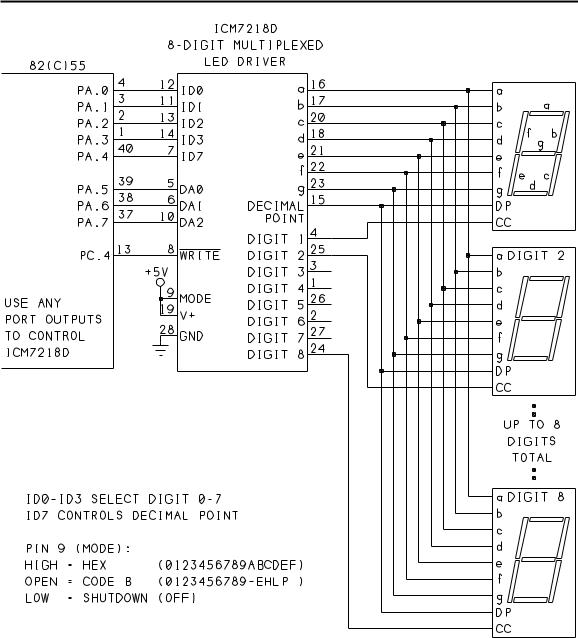
Multi-digit driver. If you want to display more than a couple of digits, there are specialized chips that will drive and control multiple-digit displays. One example from Intersil (now part of Harris Semiconductor) is the ICM7218D multiplexed display driver, which can control up to 8 common-cathode digits. Figure 8-5 illustrates. For common-anode displays, use the ICM7218C.
The segments of all eight displays connect to the 7218D’s segment-driver outputs (a-g, dp). Each display’s common cathode connects to one of eight DIGIT outputs. An internal oscillator
132 |
The Microcontroller Idea Book |
Displays
Figure 8-5. The ICM7218D can control up to eight 7-segment LEDs.
turns on each of the digits in sequence. This means that each of the displays is on just 1/8 of the time.
The 7218D drives each segment at 20 milliamperes peak current, for an average current of just 2.5 milliamperes. The chip takes advantage of the fact that LEDs can withstand relatively high pulsed currents, and that a pulsed LED actually appears brighter than a constantlydriven LED with the same average current. Twenty milliamperes is well within the allowed
The Microcontroller Idea Book |
133 |

Chapter 8
Listing 8-3. Controls eight 7-segment LEDs with ICM7218 driver.
10 |
REM address of 8255 Port A |
20 |
A=0FC00H |
30 |
REM address of 8255 control word |
40 |
X=A+3 |
50 |
REM set 8255 for all outputs |
60 |
XBY(X)=80H |
70 |
REM set WR |
80 |
XBY(X)=9 |
90 |
REM write to each digit |
100 |
FOR M=0 TO 7 |
110 |
REM step through all numbers at each digit |
120 |
FOR I=0 TO 8 |
130 |
REM add 10h to turn off decimal point |
140 |
D=I+10H+M*20H |
150 |
GOSUB 500 |
160 |
REM delay to display each digit |
170 |
K=500 |
180 |
FOR J=1 TO K : NEXT J |
190 |
NEXT I |
200 |
NEXT M |
210 |
END |
490 |
REM write data to port A and toggle W (PC.4) |
500 |
XBY(A)=D |
510 |
XBY(X)=8H |
520 |
XBY(X)=9 |
530 |
RETURN |
range for peak current for most LEDs, and the 2.5-milliampere average current causes the displays to appear brighter than you might expect. With all digits displaying 8’s, this circuit draws 140 milliamperes, so be sure your power supply can handle it.
To write a value to the display, you select the digit with data-address inputs DA0-DA2, write the data to inputs ID0-ID7, and strobe WRITE low. The WRITE pulse must be at least 400 nanoseconds wide, and ID0-ID7 must remain valid for at least 125 nanoseconds after WRITE goes high. BASIC-52 is slow enough to meet these requirements, using XBY statements to write to the port that controls the 7218C.
Pin 9 allows you to select one of three modes, which determine what digits the displays show. In Code B mode, you can display the message HELP.
134 |
The Microcontroller Idea Book |

Displays
In Figure 8-5’s circuit, an 82(C)55 controls the 7218C. For complete control, the circuit requires 10 outputs. Bits 0-4 of Port A determine the data to be written, including a decimal point controlled by ID7. If you don’t need the decimal point, tie pin 7 of the 7218C low. Bits 5-7 of Port A select the digit to write to. If you have four or fewer displays, you can tie one or more of these lines low and free up another port bit.
Port C, bit 4 controls WRITE. The display-mode input is tied high to select hexadecimal mode. If you instead tie pin 9 to a port bit, you can turn off the display by bringing the bit low. To allow selecting different modes, connect an additional output bit to the 7218D’s MODE input.
Listing 8-3 uses the 7218D to display data, using Figure 8-5’s circuit.
7-segment LCDs
An alternative to LEDs is liquid-crystal displays (LCDs). Unlike LEDs, which consume several milliamperes per segment, LCDs are voltage-controlled and require very little operating current.
Compared to LEDs, LCDs are easy to read in bright light. However, because LCDs don’t emit light as LEDs do, but merely absorb or transmit it, you need additional lighting to see them in the dark. LCDs also tend to have narrower viewing angles than LEDs. So, whether to use LEDs or LCDs may depend on where and how you will use the display.
Most 7-segment LCD modules contain two or more digits. Like the LEDs, a 7-segment LCD creates a numeral by turning on selected segments.
Each LCD segment contains a thin layer of liquid crystal between two layers of glass. Liquid crystals are organic compounds that act as electrically controlled light polarizers. In a positive-image display (the most common type), applying a voltage across a segment causes the segment to appear dark, or opaque, while removing the voltage causes the segment to appear light-colored, or transparent. Negative-image displays are opaque when not powered, and transparent when powered. By applying and removing voltages across individual segments, you can display numeric, alphabetic, and other characters.
Applying a constant voltage to an LCD segment will eventually destroy it. Instead, you must drive the segment with an alternating voltage, typically a square wave that alternately applies +5 and -5V across the segment.
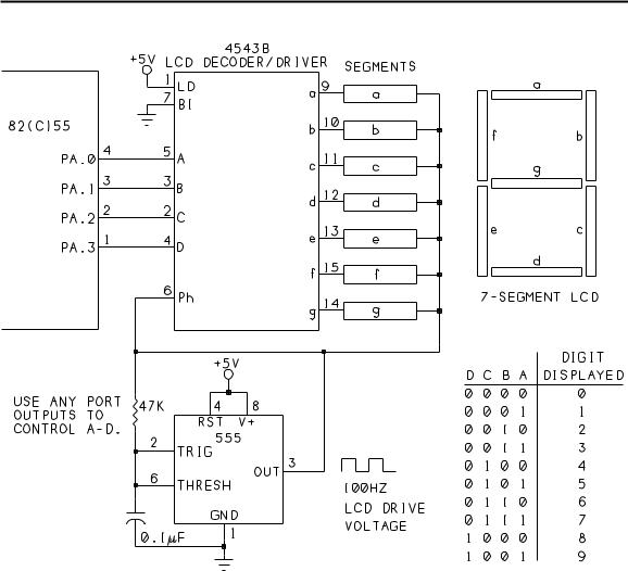
Single-digit driver. Figure 8-6 shows an LCD module driven by a 4543B LCD latch/decoder/driver. The 4543 is a lot like the 4511 LED driver, with the addition of a phase input that accepts a square wave for driving the segments. A typical drive frequency is around 100 Hertz. A 555 timer provides the phase input, or you can use any oscillator output.
The Microcontroller Idea Book |
135 |
Chapter 8
Figure 8-6. A 4543B driver can control a 7-segment LCD. A 555 timer controls the drive voltage.
As in Figure 8-4, you control the display by writing to inputs A-D. If the display contains other types of segments, such as ± or a leading 1, you can control these as well. For example, for a leading 1, connect digit 1’s two segments to pins 10 and 11 on the 4543. When you write 1 to the data inputs, the appropriate segments will light.
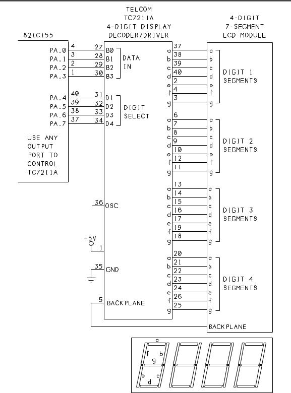
Multi-digit driver. As with the LEDs, there are driver chips for multi-digit LCD modules. Figure 8-7 shows Telcom Semiconductor’s (formerly Teldyne) TC7211A, which will drive four 7-segment LCDs, and includes an on-chip oscillator and backplane driver.
To display a number using Figure 8-7’s circuit, follow these steps:
136 |
The Microcontroller Idea Book |
Displays
Figure 8-7. With the TC7211A decoder/driver, you can control a 4-digit display with 8 port bits.
The Microcontroller Idea Book |
137 |

Chapter 8
(1)Write the number you want to display to data inputs B0-B3, and bring a digit-select input (D1-D4) high to select the digit to write to. You can use the same XBY statement to do both. For example, to write 7 to digit 2, use this statement: XBY(port address)=27H.
(2)With the data still on B0-B3, bring the digit-select input low. The data must remain on B0-B3 for at least 200 nanoseconds after the digit-select input goes low. For step 1’s example, you would write XBY(port address)=07H.
Follow the same procedure for each digit, and the TC7211 will continue to drive the appropriate segments on all four digits. To change the value of a digit, repeat steps 1 and 2.
Displaying Messages
Sometimes a device has to display more complex messages than simple LEDs and 7-segment displays can handle. For example, you might want to display messages like these:
Please enter your access code.
Select function:
Read
Program
Verify
Exit
Wind is from the west at 12 mph
Total cost = $5.82
With BASIC-52, you can use the host computer’s display, but this is no help if you want to create a stand-alone project that doesn’t require a personal computer. In these situations, a character-based dot-matrix LCD module is a solution.
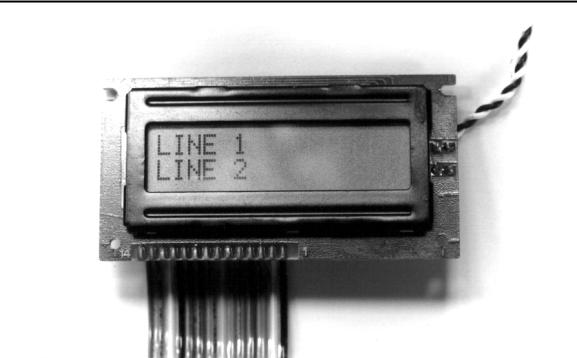
These modules can display messages made up of numbers, characters of the alphabet, and other symbols (for math functions, for example, or even symbols you design yourself). Figure 8-8 illustrates. Devices that use this type of display include laser printers and test equipment.
The Controller Chip
A special controller chip makes it easier to use LCD modules than you might think. Hitachi’s HD44780 LCD controller is an 80-lead surface-mount chip that takes care of the details of controlling the individual dots, or segments, on the display. For as low as $10, you can find complete modules that contain an LCD panel and small circuit board containing the
138 |
The Microcontroller Idea Book |
Displays
Figure 8-8. With a character-based dot-matrix LCD module, you can display messages as well as numbers.
controller chip. Applying power, reading, and writing to the module require just 14 connections, or fewer, depending on your configuration. The HD44780 can control displays of up to 80 characters.
Learning to program the HD44780 does take some time and experimenting, but the result is a useful and flexible display. Once you’ve had some practice, future projects using the displays are simpler, and you can reuse or adapt portions of your programs in other projects.
Many LCD modules use the HD44780 or a compatible controller (the OKI M6222 is an example). If a module uses the same 14-line interface discussed below, chances are it’s compatible with the HD44780.
About the Modules
The character-based LCD modules are available from many companies, including Philips, Optrex, and Densitron. The surplus market often has good deals. Complete technical information on the controller and displays is available from Hitachi and the display manufacturers, and from some distributors and catalogs.
The display of one of these modules contains one or more rows of character positions. Each character position consists of a matrix that is typically five segments, or dots, wide and eight
The Microcontroller Idea Book |
139 |

Chapter 8
segments tall. (The HD44780 can also control matrices that are 11 segments tall, for better display of characters with descenders, like g, p, and q.)
The module forms characters by turning on the appropriate segments in a character position. For example, to display an L, the module turns on one vertical column and one horizontal row of segments. For most characters, the bottom row is reserved for displaying a cursor, which leaves 35 segments to form the character.
Displays are available in several sizes. Popular sizes are 1 x 16 (1 line of 16 characters), 2 x 16, and 2 x 20. Displays larger than 80 characters require supplemental driver chips along with the HD44780, but the displays can use the same interface.
Table 8-1 summarizes the signals in the 14-line interface.
Power Supplies and Backlights
The power supply (pin 2) is a simple +5V DC. The modules contain their own oscillators to drive the LCD segments. Typical power consumption for an entire module is just a couple of milliamperes. A contrast input (pin 3) allows you to adjust for best viewing under varying light conditions, viewing angles, and temperatures.
Some LCD modules use backlighting to allow viewing in dim light. A module may be reflective (which does not use backlighting), transmissive (which must use backlighting), or transflective (which may use backlighting or not). With a transflective display, you can add a switch to enable users to turn the backlighting on or off as desired.
One popular type of backlight is an electroluminescence (EL) panel behind the LCD segments. An EL panel emits a diffuse light that provides a bright background for the LCDs. Electroluminescent backlighting requires first of all, a module that contains an EL panel, and second, an inverter module to provide the high-voltage alternating signal required to power the panel. The inverters typically convert +5 volts to around 100 volts RMS at 400 Hertz. Inverters are usually offered along with the modules that use them, so you shouldn’t have to construct your own. The backlighting requires several milliamperes.
Incandescent and LED backlights are other options for illuminating LCDs.
Inside the Display Controller
The HD44780 LCD controller is actually a small, specialized microcontroller in itself. It contains its own RAM and ROM, and executes the 11 instructions shown in Table 8-2. The instructions perform tasks like clearing the display, writing a character to the display, selecting a position on the display, and reading information from the display. To use the controller, you need to be familiar with what it contains and the instructions that control it.
140 |
The Microcontroller Idea Book |