

The Microcontroller Idea Book (Jan Axelson, 1994)
.pdfSwitches and Keypads
•A single capacitor adds debouncing. A capacitor connected at KBM (keybounce mask) sets the debounce period. With a 1-microfarad capacitor, the 74C922 ignores keypresses shorter than 10 milliseconds. Only when a keypress lasts longer than this does the chip latch the data and bring DA high. In a similar way, after the key opens, the debouncing must time out before a new key press is detected. The debounce period varies directly with capacitor size, with larger values increasing the time. By experimenting with different values, you can adjust the timing until all key bounces are ignored, yet no noticeable delay is required between key presses.
Adding a Keypad
Figure 7-9 shows the 74C922 connected to the 8052-BASIC system. The 74C922 interfaces the keypad to a 72LS244 buffer, as described in Chapter 6. The 74C922 is shown addressed at E000h, but you can use any available chip-select. Pin 13 of the 74C922 is tied low to permanently enable the data outputs. Keypresses are read by reading the buffer at E000h.
The keypad’s X and Y lines connect to their corresponding pins on the 74C922. Data outputs A-D connect to D0-D3 on the 8052’s data bus. DA, which signals when a key has been pressed, connects to INT1 on the 8052-BASIC. If you want to use polling to detect keypresses, you can use any input port pin instead of INT1.
Figure 7-9. Circuits for adding a matrix-encoded keypad to an
8052-BASIC system.
The Microcontroller Idea Book |
121 |

Chapter 7
A 1-microfarad capacitor at KBM and 0.1-microfarad capacitor at OSC give a keyboard debounce of 10 milliseconds and a scan rate of around 600 hertz. Larger values will increase the debounce time and decrease the scan rate. The 74C922’s data sheet recommends choosing KBM’s capacitor to be ten times the values of OSC’s capacitor, so be sure to change both if you change either.
Testing the Keypad
Listing 7-3 tests Figure 4’s circuit. The program waits for a key press and when one occurs, displays the value of the key on the host computer.
The following paragraphs explain the program in greater detail.
Lines 10-25 are a lookup table that translates the 74C922’s A-D outputs into an ASCII code corresponding to the key pressed. The table is stored at locations 1FF0h-1FFFh in external RAM. The lookup table is arranged with the values of the 74C922’s data outputs (0-Fh) in ascending order. Notice that the key legends (0-F) do not follow in order in the table, because the legends on the keypad correspond to the data outputs only at keys 4-6 and F.
Lines 30-50 are the main program loop. This does nothing except wait for an interrupt. When you press a key, the 74C922’s DA output goes high. The falling edge at INT1 then causes the program to jump to line 100.
Lines 100-110 read the value of the keypress at AD0-AD3 and, use the lookup table to translate the key press into an ASCII code. For example, if the key labeled “7" is pressed, Y3 goes low when X1 is scanned, and the 74C922’sAD outputs identify the keypress as 1000 in binary, or 8 decimal, which the 8052 reads at E000h. Line 100 ANDs AD0-AD7 with 0Fh to clear bits 4-7, leaving 8, the value of the keypress. In line 110, 8 + 1FF0h = 1FF8h, and the value stored at 1FF8h in external memory is 55, which is the ASCII code for the numeral 7.
Line 120 causes the character matching the keypress to display on-screen. The program then returns to the main loop to wait for another key press.
If you have a keypad with different encoding, change the lookup table to match its layout.
Customizing the Interface
Listing 7-3 does little more than test the interface, but you can use the general idea in a specific project. You can also assign special functions to individual keys. In an EPROM programmer, these might be Select device, Program, Verify, and so on. If the functions aren’t labeled on the keys, you can describe them in an on-screen menu: Press 1 to select device; press 2 to program; and so on. Then, when a keypress is detected, instead of just displaying the value of the key, your program would branch to a subroutine that corresponds to the
122 |
The Microcontroller Idea Book |

Switches and Keypads
Listing 7-3. Test program for Figure 7-9’s circuits.
10XBY(1F00H)=49 : REM 1
11XBY(1F01H)=50 : REM 2
12XBY(1F02H)=51 : REM 3
13XBY(1F03H)=67 : REM C
14XBY(1F04H)=52 : REM 4
15XBY(1F05H)=53 : REM 5
16XBY(1F06H)=54 : REM 6
17XBY(1F07H)=68 : REM D
18XBY(1F08H)=55 : REM 7
19XBY(1F09H)=56 : REM 8
20XBY(1F0AH)=57 : REM 9
21XBY(1F0BH)=69 : REM E
22XBY(1F0CH)=65 : REM A
23XBY(1F0DH)=48 : REM 0
24XBY(1F0EH)=66 : REM B
25XBY(1F0FH)=70 : REM F
30 |
DO |
40 |
ONEX1 100 |
50 |
WHILE 1=1 |
60 |
END |
100 |
KEY=XBY(0E000H).AND.0FH |
110 |
DAT=XBY(1F00H+KEY) |
120 |
PRINT CHR(DAT) |
130 |
RETI |
|
|
requested function. Chapter 8 describes how to add a small display to a system, so you don’t have to use the host computer’s display for the menu.
For some projects, you may want to use the numeric values of the keys directly, rather than interpreting them as ASCII codes. In this case, you’ll need to revise the lookup table, or create a second table that matches the numeric values of the key legends with their data outputs. For example, a data output of 0 would correspond to 1, instead of 49 (the ASCII code for 1). Again, you usually can’t use the keypad encoder’s data outputs directly because they don’t correspond to the values printed on the keys.
If an application requires that users enter multi-digit numbers on the keypad, your program will have to translate the individual digits into a single value. Listing 7-4 is a program that waits for the user to enter a 4-digit hex address, then displays the data stored at that address in external RAM.
The Microcontroller Idea Book |
123 |

Chapter 7
Listing 7-4. Reads the data stored a a 4-digit address entered by the user on a keypad.
1 REM lookup table stores the numeric value of each key
10XBY(1F00H)=1 : REM 1
11XBY(1F01H)=2 : REM 2
12XBY(1F02H)=3 : REM 3
13XBY(1F03H)=0CH :REM C
14XBY(1F04H)=4 : REM 4
15XBY(1F05H)=5 : REM 5
16XBY(1F06H)=6 : REM 6
17XBY(1F07H)=0DH :REM D
18XBY(1F08H)=7 : REM 7
19XBY(1F09H)=8 : REM 8
20XBY(1F0AH)=9 : REM 9
21XBY(1F0BH)=0EH :REM E
22XBY(1F0CH)=0AH :REM A
23XBY(1F0DH)=0 : REM 0
24XBY(1F0EH)=0BH :REM B
25XBY(1F0FH)=0FH :REM F
30 |
A=0 |
40 |
COUNT=3 |
50 |
PRINT “Please enter a 4-digit hex address to read: ” |
60 |
DO |
70 |
ONEX1 100 |
80 |
WHILE 1=1 |
90 |
END |
100 |
KEY=XBY(0E000H).AND.0FH: REM read the key |
110 |
DAT=XBY(1F00H+KEY): REM find its value |
120 |
A=A+(DAT*(16**COUNT)): REM add to the total |
130 |
COUNT=COUNT-1: REM keep track of # of digits read |
140 |
PH0. DAT, |
150 |
IF COUNT=-1 THEN GOSUB 200: wait for 4 digits |
160 |
RETI |
200 |
PRINT : PH0. XBY(A)," is stored at address “,A |
210 |
PRINT “Please enter another 4-digit address to read: ” |
220 |
COUNT=3 |
230 |
A=0 |
240 |
RETI |
124 |
The Microcontroller Idea Book |

Displays
8
Displays
In addition to switches and keypads for user input, most projects also include a display to let users know what’s going on inside. The type of display depends on the kinds of information you want to show. For simple status indicators, discrete LEDs will do the job. For numbers, you can use 7-segment displays. And if you need to display text or other symbols in addition to numbers, character-based LCD modules are a good solution. This chapter will show how to use each of these in an 8052-BASIC system.
Using LEDs
Discrete, or individual LEDs (light-emitting diodes) are an easy way to indicate status, such as On, Ready, Mode selected, and so on. They are colorful, eye-catching, and easy to interface to 5-volt logic. Available colors now include blue as well as red, green, and yellow. Some individual LED packages can emit red, green, or amber light, depending on the voltages applied.
Like other diodes, current passes through an LED in one direction only. When a positive voltage is applied to the anode, current flows and electrons migrate across an energy gap in the LED, causing it to emit light. The size of the energy gap determines the voltage drop across the LED, as well as the color of light emitted. A tinted case can also vary the color.
The Microcontroller Idea Book |
125 |

Chapter 8
Table 8-1. The forward voltage drop across an LED varies with the color.
LED color |
typical forward voltage (volts) |
Red |
1.6 |
Green |
2.0 |
Yellow |
2.0 |
Blue |
3.2 |
Table 8-1 shows typical forward voltages for different colors of LEDs. Typical LED operating currents are between 10 and 20 milliamperes. For a bright display with low power consumption, look for types labeled high efficiency.
One disadvantage to LEDs is that the light from most is hard to detect in bright light, especially outdoors. A tinted, transparent sheet of plastic mounted over the display can make it more visible in bright light. For red LEDs, transparent red or purple works well.
For best visibility over a wide area, look for LEDs with a wide viewing angle. This means that the LED emits light in a wide cone, so you don’t need to view it straight-on.
LED Interfaces
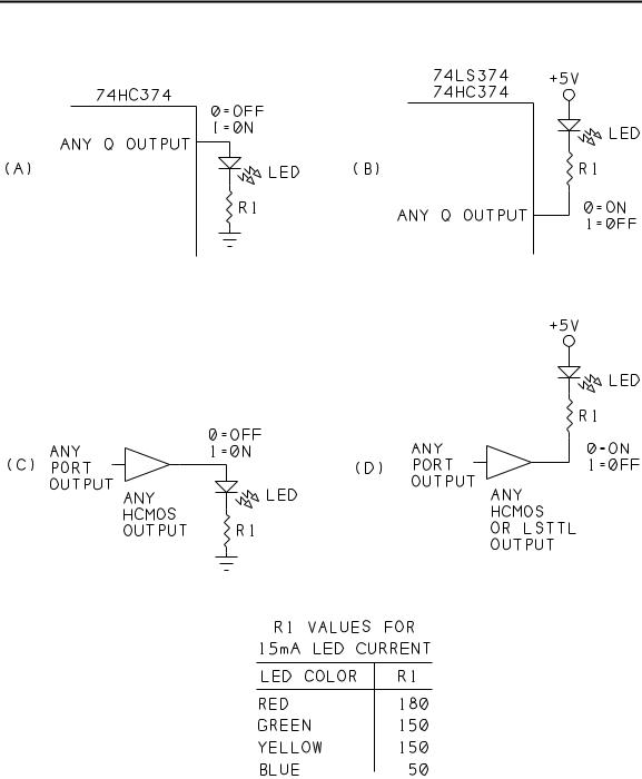
Figure 8-1 shows examples of LED interfaces to output ports in an 8052-BASIC system. The outputs of the 80(C)52 and 82(C)55 can’t provide enough current to drive an LED directly. But you can drive an LED with a 74LS374 or 74HC374 latch (A, B), or with a buffer or inverter driven by any output port (C, D).
With LSTTL drivers, you should design your circuit so that a low output turns on the LED, since LSTTL outputs can sink more current than they can source. With HCMOS or HCTMOS outputs, either a high or low output can turn on the LED.
Use a series resistor to limit the current through the LED. For a brighter display, decrease the value of the resistor. Most LEDs can handle 20 milliamperes of continuous current. You can measure the current directly by connecting an ammeter in series with the LED and resistor. Or, you can calculate the current by measuring the the voltage across the series resistor and dividing it by the resistor’s value. For example, 2.25V/150 ohms = 0.015 amperes, or 15 milliamperes.
Both LSTTL and HCMOS devices are capable of 20-milliampere output currents. At these higher currents, the output voltage isn’t specified, but should be enough to light an LED.
To turn on an LED at a port, write a 1 or 0, as appropriate, to the bit that controls it, as described in Chapter 6. Listing 8-1 assumes that you have eight LEDs connected to the
126 |
The Microcontroller Idea Book |
Displays
Figure 8-1. LED interfaces to output ports. Use an HCMOS output if you want a high output to turn on the LED. Use either HCMOS or LSTTL if you want a low output to turn on the LED.
The Microcontroller Idea Book |
127 |

Chapter 8
Listing |
8-1. Controls eight LEDs at an output port. |
10 |
A=0E000H: REM address of LEDs |
20 |
L=0FFH: REM initial control value for LEDs |
20 |
XBY(A)=L: REM turn off all LEDs |
30 |
DO |
40 |
INPUT “Select an LED (0-7): ”,B |
50 |
INPUT “Turn on or off (0=off, 1=on)? ”,C |
60 |
IF C=0 THEN L=L.AND.(0FFH-2**B) |
70 |
IF C=1 THEN L=L.OR.2**B |
90 |
XBY(A)=L |
80 |
WHILE 1=1 |
90 |
END |
|
|
outputs of a 74LS374 addressed at E000h. The LEDs are connected as in Figure 8-1B , with logic-low outputs turning on the LEDs. Listing 8-1 tests the circuit by allowing you to turn individual LEDs on and off.
Bi-color LEDs
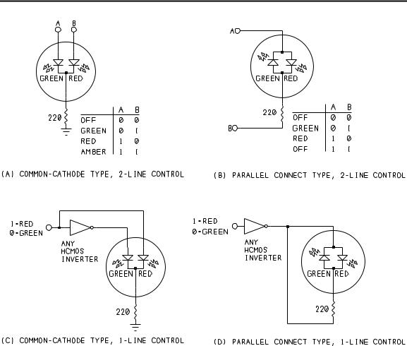
Bi-color LEDs have both a red and a green LED inside a single package. By turning on one, both, or neither, you can use a single indicator to show as many as four states. Some bicolor LEDs have two leads, while others have three. Figure 8-2 illustrates.
In the 3-lead, or common-cathode type, the cathodes of both LEDs connect internally (A). To turn on an LED, you ground the cathodes through a current-limiting resistor and apply power to the anode of the desired LED. When both LEDs are powered, you get an amber light. Removing power from both turns the LED off, giving a total of four states that the device can display. Instead of the one current-limiting resistor shown, you can connect a resistor to each anode, to set the current through each LED individually.
In a 2-lead, or parallel-connected, bicolor LED, the anode of each LED connects internally to the other’s cathode (B). To turn on the red LED, you apply +5V to terminal A and ground terminal B. To turn on the green LED, you do the reverse: terminal A is ground, and terminal B is +5V. With this type, you can’t turn on both LEDs at once.
With either type, by adding an inverter, you can use a single output to control both LEDs (C, D).
128 |
The Microcontroller Idea Book |
Displays
Figure 8-2. Ways to connect bicolor LEDs .
7-segment Displays
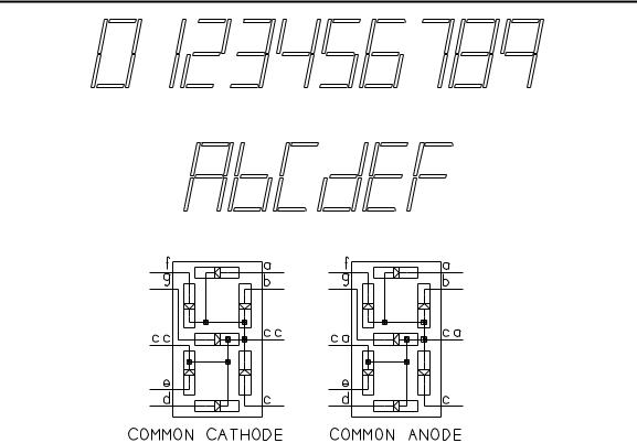
If you want to display numbers, 7-segment displays will do the job. Each digit on the display contains seven segments. Numerals are displayed by turning on different combinations of segments, as Figure 8-3 shows. Decoder chips make it easy to operate one or more displays with a minimum of programming and added components. Seven-segment displays are available as LEDs, where each segment is a light-emitting diode, and as LCDs, where each segment is a liquid-crystal display. We’ll look at the LED type first.
7-segment LEDs
A 7-segment LED contains seven individual LEDs arranged in the pattern shown in Figure 8-3. Sometimes there is also a decimal point (or two, one on each side). There are also special leading-digit modules that display only a 1 and a plus-or-minus symbol.
The Microcontroller Idea Book |
129 |
Chapter 8
Figure 8-3. A 7-segment display can show numbers from 0 to 9, plus hex digits A-F. In a common-cathode LED display, all of the cathodes connect together, while in a common-anode display, all of the anodes connect.
The displays come in two types: common-anode or common-cathode. In a common-anode display, the anodes of each segment connect internally. To use the display, you connect the anodes to a voltage source and turn on individual segments by grounding them through a current-limiting resistor. A common-cathode display is the opposite: the cathodes connect internally, so you ground the cathodes and apply voltages through current-limiting resistors at the segments you want to light.
Deciphering pinouts
Unfortunately, there isn’t much standardization for pinouts of 7-segment displays. If you don’t know the pinout for a display, you can find it by experimenting. You’ll need a 330-ohm resistor and a 5-volt supply.
Sometimes you’ll find CC or CA stamped on the package to indicate common cathode or common anode. If even this information is lacking, begin by connecting one lead of the
130 |
The Microcontroller Idea Book |