

Chapter 6 - Wiring Techniques
generally doesn't matter which power wire is connected to the power terminals as long as both are connected and insulated from each other. In the case of the LED, though, the (+) and (-) connections must be made to the proper LED wires and insulated from each other if the LED is to light. The same is true for the DC powered PLC. The difference with the
PLC is that if it is connected wrong, the damage can be very expensive.
6-4. Input Wiring
The inputs of modern PLCs are generally opto-isolators. An opto-isolator is a device consisting of a light producing element such as an LED and a light sensing element such as a phototransistor. When a voltage is applied to the LED, light is produced which strikes the photo-detector. The photo-detector then provides an output; in the case of a phototransistor, it saturates. The separation of the sensing and output devices in the optoisolator provide the input to the PLC with a high voltage isolation since the only connection between the input terminal and the input to the PLC is a light beam. The light producing element and any current limiting device and protection components determine the input voltage for the opto-isolator. For instance, an LED with a series current limiting resistor could be sized to accept 5 VDC, 24 VDC or 120 VDC. To accept an AC signal, two back- to-back LED's with a series current limiting resistor are used. The resistor could be sized to allow the LED to light with 5 VAC, 24 VAC, 120 VAC or 240 VAC or any voltage we desire. PLC manufacturers offer different models having various input voltage specifications. The PLC with the input voltage specification is chosen at the time of purchase.
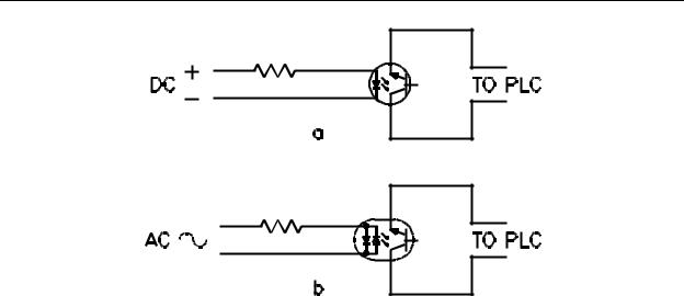
Figure 6-4 shows two types of opto-isolators which are utilized. The DC unit is shown in (a) and the AC unit in (b). The wires from the switch or sensor are connected to the left side of the drawing. The right side of the device is connected internally to the actual PLC input. Notice that each opto-isolator has a series resistor to limit the device current. Also notice that the AC unit has back-to-back LED's inside the device so light is produced on both half cycles of the input voltage.
6-5
Chapter 6 - Wiring Techniques
Figure 6-4 - Typical PLC Input Circuit
Since the input to the PLC is an LED, we can visualize the wiring of the input by thinking of it as some type of device controlling a lightbulb and requiring that the input device lights the lightbulb. The input device may be a switch or some type of on/off sensor such as a photosensor or proximity sensor, but the problem is always the same; wire the device so the LED will light when we want the input to be detected as ON. For the DC unit, you can see that the polarity must be observed for the LED to light. In the case of the AC unit, since there is a forward biased LED no matter which way current flows, polarity does not matter. In fact, some manufacturers produce PLC's with AC/DC inputs which are really the AC unit. When using this type of PLC, the polarity of the input, if it is DC, does not matter because one of the LED's will light no matter which polarity voltage is applied.
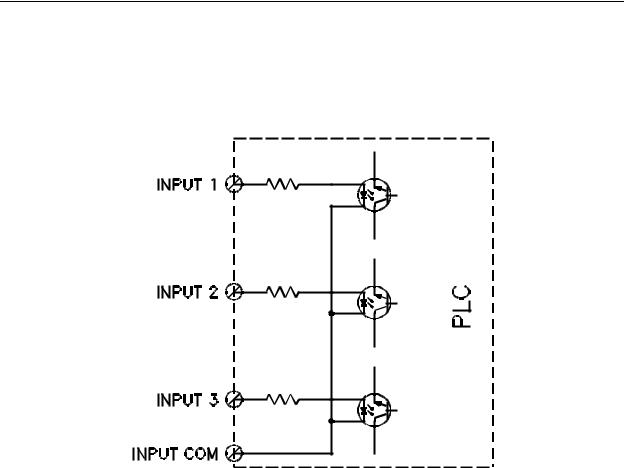
PLC inputs are configured in one of two ways. In some units all inputs are isolated from each other, that is, there is no common connection between any two inputs. Other units have one side of each input connected to one common terminal. The PLC utilized depends on whether the power for all input devices is common or not. The power supply for the inputs may be either external or internal to the PLC. In low voltage units (24 VDC), a power supply capable of supplying enough current to turn on all inputs will be internal to the PLC. If all inputs will be from switches, no other power supply will be required for the inputs. This internal power supply may not be large enough to also supply any active sensors (photodetectors or proximity detectors) which may be connected. If not, an external supply will have to be obtained. The PLC specification will indicate the capacity of this internal power supply. The internal schematic for the inputs of a PLC having 3 inputs with common connection is shown in Figure 6-5. One can see that all three opto-isolators have one wire connected to the same terminal, the INPUT COM. Also, the wire that is connected to the INPUT COM terminal for each opto-isolator is the negative connection for
6-6
Chapter 6 - Wiring Techniques
lighting the LED in the opto-isolator. This means that any device connected to the terminals INPUT 1, INPUT 2 and INPUT 3 must have the opposite end of the device connected to a positive voltage in order to light the LED in the opto-isolator. If more than one power supply is used to power the devices, all of them have to have the negative power lead connected to INPUT COM because that is the only terminal available to connect to the negative input of the opto-isolator.
Figure 6-5 - PLC With Common Inputs
A PLC with isolated inputs is shown in Figure 6-6. Since each input has no connection with any other input, each one may be connected as desired with no concern for power supply interaction. The only requirement is that for the LED in the opto-isolator to light, a positive voltage must be applied to the (+) terminal of the PLC input with respect to the (-) terminal.
6-7

Chapter 6 - Wiring Techniques
Figure 6-6 - PLC With Isolated Inputs
6-5. Inputs Having a Single Common
Let us now look at the wiring connections required to implement a system in which all inputs have a common power supply. For this type of system a PLC with inputs having a single common connection may be used as shown in Figure 6-5. A system of this type is shown in Figure 6-7.
6-8
Chapter 6 - Wiring Techniques
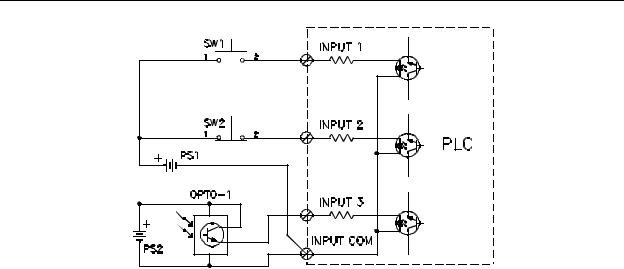
Figure 6-7 - Non-Isolated Input Wiring
This drawing shows three devices connected to the PLC, a normally open pushbutton (SW1), a normally closed pushbutton (SW2) and a photodetector (OPTO-1). The system also has two power supplies providing power for the input devices PS1 and PS2. Notice that the two power supplies have the negative side connected to the INPUT
COM terminal. Let us first look at the connection for normally open pushbutton SW1.
Remember to think of the input in terms of lighting the LED in the opto-isolator. Since the LED must be forward biased to light, the positive voltage must be applied to the anode of the LED and the negative voltage to the cathode. All three opto-isolators have the cathode lead of the LED connected to the INPUT COM terminal. That means that any power supply used to light the LED's must have the negative lead connected to the INPUT COM terminal.
For that reason, both PS1 and PS2 have the negative lead of the supply connected to the INPUT COM terminal. With the negative lead of PS1 connected to the cathode of the INPUT 1 LED, the positive lead of PS1 must be connected to the anode of the INPUT 1
LED. If this were done, the INPUT 1 LED would light and the PLC would accept INPUT 1 as being turned ON. The problem is that INPUT 1 would always be ON. To control this INPUT, SW1 is placed in series with the positive power supply lead going to INPUT 1. If SW1 is not being pressed, the switch would be open (remember it is a normally open switch) and no voltage would be applied across the INPUT 1 LED. The LED would not light and the PLC would accept INPUT 1 as being OFF. If SW1 is pressed, the SW1 contacts will close and the positive lead of PS1 will be connected to the anode of the INPUT 1 LED causing the LED to light. This will cause the PLC to accept INPUT 1 as being ON.
INPUT 2 is connected similar to INPUT 1 except that switch SW2 is a normally closed pushbutton. Since it is normally closed if the switch is not being pressed, the positive lead of PS1 will be connected to the INPUT 2 LED, causing it to light. This will
6-9

Chapter 6 - Wiring Techniques
cause the PLC to accept INPUT 2 as being ON. When pushbutton switch SW2 is pressed, the normally closed contacts of the switch will open removing power from the INPUT 2 LED. With the LED not lit, the PLC will accept INPUT 2 as being OFF.
INPUT 3 is connected to photodetector OPTO-1. OPTO-1 is a photodetector with an NPN transistor output. In operation, OPTO-1 requires DC power and for that reason
PS2 is connected to the device. Notice that the collector of OPTO-1 is connected to the positive terminal of PS2 and that the emitter is connected to INPUT 3. When light strikes the phototransistor in OPTO-1, the transistor saturates and the resistance from collector to emitter becomes very low. When the transistor saturates, INPUT 3 is pulled to the positive terminal of PS2. This will cause the LED for INPUT 3 to light since it will have positive voltage on the anode and negative on the cathode. When the LED lights, the PLC will accept INPUT 3 as being ON. When no light strikes the phototransistor in OPTO-1, the transistor will shut off presenting a high resistance from collector to emitter. This high resistance will prevent current from flowing in the INPUT 3 LED and the LED will not light. With the LED not lit, the PLC will accept INPUT 3 as being OFF.
A potential problem exists at INPUT 2. SW2 is a normally closed pushbutton and power is always applied to INPUT 2. If something should happen to power supply PS1, the PLC would have to assume that SW2 had been pressed since the LED for INPUT 2 would not be lit. For this reason, it is good practice to use normally open switches and other devices to prevent a false decision by the PLC on the condition of the input device.
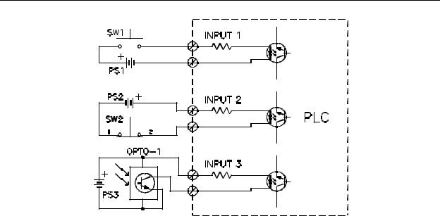
Figure 6-8 illustrates a system utilizing a PLC with isolated inputs. This system has three power supplies, one for each input device. INPUT 1 is supplied by power supply PS1 with normally open pushbutton switch SW1. The negative terminal of power supply PS1 is connected to the cathode terminal of the opto-isolator for INPUT 1. The positive terminal of PS1 is connected to the anode of the LED for INPUT 1 through SW1. When SW1 is pressed, positive potential is applied to the LED and it lights. The PLC accepts this as INPUT 1 ON. With the switch SW1 released, the normally open contacts are open and no power is applied to the LED and the PLC accepts INPUT 1 as being OFF.
6-10
Chapter 6 - Wiring Techniques
Figure 6-8 - Isolated Input Wiring
INPUT 2 is connected to normally closed pushbutton switch SW2 and power supply PS2. In this case however, the positive terminal of PS2 is permanently connected to the anode terminal of the LED for INPUT 2. The cathode lead of the LED is connected to the negative terminal of PS2 through the action of SW2. Since SW2 is normally closed, power will normally be applied to the LED for INPUT 2 and the LED will be lit. This will cause the PLC to accept INPUT 2 as being ON. When normally closed pushbutton switch SW2 is pressed, power is removed from the LED and it does not light. This causes the PLC to accept INPUT 2 as being OFF. The potential problem noted in the previous paragraph associated with the use of a normally closed switch also exists here.
INPUT 3 is connected as before to a photodetector OPTO-1. However, this time the positive terminal of power supply PS3 is connected directly to the anode of the LED for
INPUT 3. The collector of the phototransistor is connected to the cathode terminal of the LED and the emitter of the phototransistor is connected to the negative terminal of power supply PS3. With this configuration, when the phototransistor saturates, the cathode of the
LED for INPUT 3 is pulled to the negative terminal of power supply PS3 causing current to flow in the LED. With the LED lit, the PLC will accept INPUT 3 as being ON. When the phototransistor turns off, current through the LED stops flowing and the LED does not light. This causes the PLC to accept INPUT 3 as being OFF.
Notice that with isolated inputs, wiring can be arranged in different ways to suit different requirements. Generally, inputs have a common terminal and when they are low voltage inputs, the power supply is part of the PLC and external power is not required
6-11