

Creating a Solid Model
Lens Element
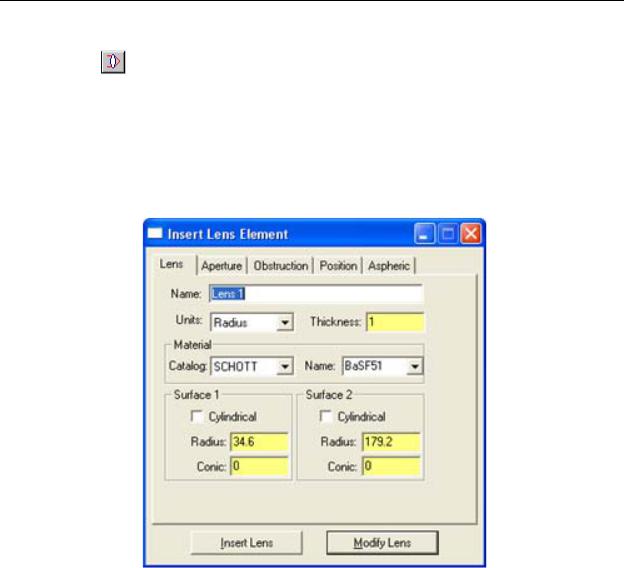
The Insert|Lens Element menu or Insert Lens toolbar button opens a tabbed dialog box that allows you to specify completely a lens element including curvatures (or radii); thickness; material; aperture and obstruction shape and dimensions; and position and orientation of the element. You can make a mirror using Insert|Lens Element by creating the mirror with the desired shape, then applying a reflective coating to it.
Note: An obstruction is a common term from lens design. An obstruction in TracePro creates a hole in the lens.
FIGURE 2.8 - Insert Lens Element dialog box: Lens tab
After you have entered all the data to specify the element press Insert Lens at the bottom of the dialog box to create the element. You can create as many elements as you wish. Simply edit the data for the new element and press Insert Lens again. To close the dialog box, click on the close button on the top bar of the dialog box, or press the Esc Key on your keyboard.
The Insert|Lens Element dialog box is a modeless dialog box, so you can leave it open while you do other things like inserting other solid objects, moving objects, changing the view, or applying properties.
Note the Modify Lens button in Figure 2.8. You can select an existing Lens object and then use the Insert|Lens Element dialog box to access and change the data by pressing the Modify Lens button. Note that the Modify button will be disabled if you don’t have an appropriate Lens selected in the model window.
An example of inserting a lens developed in the OSLO lens design software is shown in “Anisotropic Surface Property” on page 9.45
2.8 |
TracePro 5.0 User’s Manual |
Defining TracePro Solids
Lens tab
Using the lens tab you can enter
1.Curvature or Radius of each surface
2.Conic constant of each surface
3.Center thickness, the vertex to vertex between the two surfaces.
4.Material Catalog
5.Material Name
If you check one of the Cylindrical boxes, the dialog will change the conic constant to rotation. The rotation entry specifies the angle about the z-axis to rotate the cylinder in degrees.
The default glass is SCHOTT BK7.
Once you have completely specified the lens, press Insert Lens, and the lens will be created. The surfaces are created according to the sag equation
c |
ν |
ρ2 |
|
+ ∑Aι ρι, |
|
z= |
|
|
(2.1) |
||
|
2 |
2 |
|||
1 + 1 – (1 + K)c v ρ |
|
ι = 1 |
|
||
where ρ2=X2+Y2, cν is the curvature of the surface, K is the conic constant and Ai
is an aspheric coefficient. The X, Y, Z coordinates above are local coordinates relative to the vertex of the surface. See “Aspheric tab” on page 2.12 for details on entering Aspheric lens terms.
TABLE 2.1. Conic Constant Values
K (Conic Constant) |
Conic Type |
|
|
less than -1 |
hyperboloid |
|
|
-1 |
paraboloid |
|
|
between -1 and 0 |
ellipsoid |
|
|
0 |
spheroid |
|
|
greater than 0 |
oblate spheroid |
|
|
To edit a lens element, as a general rule select the Modify button in the Insert|Lens Element dialog box (version 1.4 files or later). The Modify button lets you make a series of sequential edits.
Here are the steps to alter a lens element:
1.Select the lens object in the model window or on the system tree.
2.Select Insert|Lens Element.
3.Edit the data and click Modify Lens in the dialog box.
TracePro applies your changes.
If you use another tool to edit a lens element—selecting one of the Boolean operations, for example—TracePro no longer recognizes that the lens element is still a “lens element.” For example, if you subtract a cylinder from a lens by the means of a Boolean operation, TracePro sees the result as a generic object rather than a lens object. Of course you can use the “obstruction” tabbed dialog to
TracePro 5.0 User’s Manual |
2.9 |
Creating a Solid Model
accomplish the same step as long as the cylinder is aligned along the axis of the lens, but in this case the lens object status is retained.
In general, altering a lens element is best done by selecting Modify Lens from the Insert|Lens Element dialog box. Editing the lens element in this way lets you go back as often as you want to make further changes.
Aperture tab
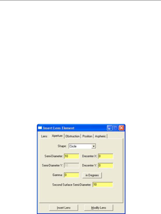
Using the Aperture tab (see Figure 2.9) you set:
1.Aperture shape: defines the cross-sectional shape of the lens orthogonal to the axis. It can be Circle, Rectangle, or Ellipse;
2.Aperture semi-diameter:s the radii of the lens aperture in the X and Y directions in the model units. Note that the Y dimension is not allowed for a circle shape;
3.Aperture Decenters: the decenter of the lens in the X and Y directions in the model units;
4.Aperture gamma: the orientation of the lens with respect to the optical axis, with X denoting the local horizontal axis and Y the local vertical axis. The value, either in Degrees or in Radians denotes the rotation of the lens around the local Z (i.e., optical) axis; and
5.Aperture second surface semi-diameter: allows for the second surface of a single lens to have a different semi-diameter than that of the first surface. Prescriptions from lens design codes (e.g., OSLO) often have this situation; therefore, the inclusion of this additional parameter ensures there is no spurious loss of aperture data when clicking on the Modify Lens button
FIGURE 2.9 - Insert Lens Element dialog box: Aperture tab
2.10 |
TracePro 5.0 User’s Manual |

Defining TracePro Solids
Obstruction tab
The obstruction used by TracePro refers to an opening or hole in the lens. To truly obscure a portion of the lens, insert a thin block or cylinder with an opaque Surface Property. Using the Obstruction tab (see Figure 2.10)you set:
1.Obstruction shape: options are None, Circle, Rectangle, and Ellipse;
2.Obstruction semi-diameters: the radii of the obstruction in the local X and Y directions in the model units;
3.Obstruction decenters: the decenters from the local optical axis of the obstruction in the local X an Y directions in the model units; and
4.Obstruction gamma: the orientation of the obstruction with respect to the optical axis, with X denoting the local horizontal axis and Y the local vertical axis. The value, either in Degrees or in Radians denotes the rotation of the obstruction around the local Z (i.e., optical) axis
The obstruction shape options are none, circle, rectangle, or ellipse.
FIGURE 2.10 - Insert Lens Element dialog box: Obstruction tab
Position tab
Using the Position tab (see Figure 2.11) you set:
1.The X, Y, Z coordinates of the vertex of the first surface of the element, in global coordinates;
2.The X, Y, Z rotation angles (tilt) of the first surface or entire element;
3.The X, Y, Z decenters of the second surface with respect to the first suface (i.e., these are local offsets with respect to item (1) above); and
TracePro 5.0 User’s Manual |
2.11 |