


Lab 5.5.2: Examining a Route
Topology Diagram
Addressing Table
Device |
Interface |
IP Address |
Subnet Mask |
Default Gateway |
|
|
|
|
|
|
|
R1-ISP |
S0/0/0 |
10.10.10.6 |
255.255.255.252 |
N/A |
|
|
|
|
|
||
Fa0/0 |
192.168.254.253 |
255.255.255.0 |
N/A |
||
|
|||||
|
|
|
|
|
|
R2-Central |
S0/0/0 |
10.10.10.5 |
255.255.255.252 |
10.10.10.6 |
|
|
|
|
|
||
Fa0/0 |
172.16.255.254 |
255.255.0.0 |
N/A |
||
|
|||||
|
|
|
|
|
|
|
N/A |
192.168.254.254 |
255.255.255.0 |
192.168.254.253 |
|
Eagle Server |
|
||||
|
|
|
|
||
N/A |
172.31.24.254 |
255.255.255.0 |
N/A |
||
|
|
||||
|
|
|
|
|
|
hostPod#A |
N/A |
172.16.Pod#.1 |
255.255.0.0 |
172.16.255.254 |
|
|
|||||
|
|
|
|
|
|
hostPod#B |
N/A |
172.16.Pod#.2 |
255.255.0.0 |
172.16.255.254 |
|
|
|||||
|
|
|
|
|
|
S1-Central |
N/A |
172.16.254.1 |
255.255.0.0 |
172.16.255.254 |
|
|
|||||
|
|
|
|
|
All contents are Copyright © 1992–2007 Cisco Systems, Inc. All rights reserved. This document is Cisco Public Information. |
Page 1 of 7 |
CCNA Exploration |
|
Network Fundamentals: OSI Network Layer |
Lab 5.5.1: Examining a Route |
Learning Objectives
Upon completion of this lab, you will be able to:
•Use the route command to modify a Windows computer routing table.
•Use a Windows Telnet client command telnet to connect to a Cisco router.
•Examine router routes using basic Cisco IOS commands.
Background
For packets to travel across a network, a device must know the route to the destination network. This lab will compare how routes are used in Windows computers and the Cisco router.
Some routes are added to routing tables automatically, based upon configuration information on the network interface. The device considers a network directly connected when it has an IP address and network mask configured, and the network route is automatically entered into the routing table. For networks that are not directly connected, a default gateway IP address is configured that will send traffic to a device that should know about the network.
Scenario
Using a pod host computer, examine the routing table with the route command and identify the different routes and gateway IP address for the route. Delete the default gateway route, test the connection, and then add the default gateway route back to the host table.
Use a pod host computer to telnet into R2-Central, and examine the routing table.
Task 1: Use the route Command to Modify a Windows Computer Routing Table.
C:\>netstat –r
Route Table
=======================================================================
Interface List
0x1 ......................... MS TCP Loopback interface
0x20005 ...00 16 76 ac a7 6a Intel(R) 82562V 10/100 Network Connection
=======================================================================
=======================================================================
Active Routes: |
|
|
|
|
Network Destination |
Netmask |
Gateway |
Interface |
Metric |
0.0.0.0 |
0.0.0.0 |
172.16.255.254 |
172.16.1.2 |
1 |
127.0.0.0255.0.0.0 127.0.0.1 127.0.0.1 1
172.16.0.0255.255.0.0 172.16.1.2 172.16.1.2 20
172.16.1.2255.255.255.255 127.0.0.1 127.0.0.1 20
172.16.255.255 |
255.255.255.255 |
172.16.1.2 |
172.16.1.2 |
20 |
255.255.255.255 |
255.255.255.255 |
172.16.1.2 |
172.16.1.2 |
1 |
Default Gateway: |
172.16.255.254 |
|
|
|
=======================================================================
Persistent Routes: None
C:\>
Figure 1. Output of the netstat Command
Shown in Figure 1, output from the netstat –r command is useful to determine route and gateway information.
All contents are Copyright © 1992–2007 Cisco Systems, Inc. All rights reserved. This document is Cisco Public Information. |
Page 2 of 7 |

CCNA Exploration |
|
Network Fundamentals: OSI Network Layer |
Lab 5.5.1: Examining a Route |
Step 1: Examine the active routes on a Windows computer.
A useful command to modify the routing table is the route command. Unlike the netstat –r command, the route command can be used to view, add, delete, or change routing table entries. To view detailed information about the route command, use the option route /?.
An abbreviated option list for the route command is shown below:
route PRINT |
Prints active routes |
route ADD |
Adds a route: |
|
route ADD network MASK mask gateway |
route DELETE |
Deletes a route: |
|
route DELETE network |
route CHANGE |
Modifies an existing route |
To view active routes, issue the command route PRINT:
C:\ >route PRINT
=======================================================================
Interface List
0x1 ........................... MS TCP Loopback interface
0x70003 ...00 16 76 ac a7 6a .Intel(R) 82562V 10/100 Network Connection
=======================================================================
=======================================================================
Active Routes: |
|
|
|
|
|
|
Network Destination |
Netmask |
Gateway |
Interface |
Metric |
||
0.0.0.0 |
|
0.0.0.0 |
172.16.255.254 |
172.16.1.2 |
1 |
|
127.0.0.0 |
|
255.0.0.0 |
127.0.0.1 |
127.0.0.1 |
1 |
|
172.16.0.0 |
|
255.255.0.0 |
172.16.1.2 |
172.16.1.2 |
20 |
|
172.16.1.2 |
255.255.255.255 |
127.0.0.1 |
127.0.0.1 |
20 |
||
172.16.255.255 |
255.255.255.255 |
172.16.1.2 |
172.16.1.2 |
20 |
||
255.255.255.255 |
255.255.255.255 |
172.16.1.2 |
172.16.1.2 |
1 |
||
Default Gateway: |
|
172.16.255.254 |
|
|
|
|
=======================================================================
Persistent Routes: None
C:\>
Verify network connectivity to Eagle Server:
C:\> ping eagle-server.example.com
Pinging eagle-server.example.com [192.168.254.254] with 32 bytes of data:
Reply from 192.168.254.254: bytes=32 time<1ms TTL=63
Reply from 192.168.254.254: bytes=32 time<1ms TTL=63
Reply from 192.168.254.254: bytes=32 time<1ms TTL=63
Reply from 192.168.254.254: bytes=32 time<1ms TTL=63
Ping statistics for 192.168.254.254:
Packets: Sent = 4, Received = 4, Lost = 0 (0% loss),
Approximate round trip times in milli-seconds:
Minimum = 0ms, Maximum = 0ms, Average = 0ms
C:\>
What is the gateway address to eagle-server.example.com?
____________________________________________________________________________
All contents are Copyright © 1992–2007 Cisco Systems, Inc. All rights reserved. This document is Cisco Public Information. |
Page 3 of 7 |

CCNA Exploration |
|
Network Fundamentals: OSI Network Layer |
Lab 5.5.1: Examining a Route |
Step 2: Delete a route from the Windows computer routing table.
How important is the default gateway route? Delete the gateway route, and try to ping Eagle Server. The syntax to remove the default gateway route is:
route DELETE network
C:/> route DELETE 0.0.0.0
Examine the active routing table and verify that the default gateway route has been removed:
What is the default gateway IP address?
____________________________________________________________________________
Try to ping Eagle Server. What are the results?
____________________________________________________________________________
If the default gateway IP address is removed, how can the DNS server be reached to resolve eagleserver.example.com?
Can other LAN devices be reached, such as 172.16.255.254?
____________________________________________________________________________
Step 3: Insert a route into the Windows computer routing table.
In the following configuration, use the IP address assigned to your host pod interface. The syntax to add a route to the Windows computer routing table is:
route ADD network MASK mask gateway-IP address
C:/> route ADD 0.0.0.0 MASK 0.0.0.0 172.16.255.254
Examine the active routing table, and verify that the default gateway route has been restored:
Has the default gateway route been restored? __________:
Try to ping Eagle Server. What are the results?
____________________________________________________________________________
Task 2: Use a Windows Telnet Client Command telnet to Connect to a Cisco Router.
In this task, uou will telnet into the R2-Central router and use common IOS commands to examine the router routing table. Cisco devices have a Telnet server and, if properly configured, will permit remote logins. Access to the router is restricted, however, and requires a username and password. The password for all usernames is cisco. The username depends on the pod. Username ccna1 is for users on pod 1 computer, ccna2 is for students on pod 2 computers, and so on.
Step 1: Using the Windows Telnet client, log in to a Cisco router.
Open a terminal window by clicking Start > Run. Type cmd, and click OK. A terminal window and prompt should be available. The Telnet utility has several options and can be viewed with the telnet /? command. A username and password will be required to log in to the router. For all usernames, the corresponding password is cisco.
All contents are Copyright © 1992–2007 Cisco Systems, Inc. All rights reserved. This document is Cisco Public Information. |
Page 4 of 7 |

CCNA Exploration |
|
Network Fundamentals: OSI Network Layer |
Lab 5.5.1: Examining a Route |
Pod Number |
Username |
|
|
1 |
ccna1 |
2 |
ccna2 |
3 |
ccna3 |
4 |
ccna4 |
5 |
ccna5 |
6 |
ccna6 |
7 |
ccna7 |
8 |
ccna8 |
9 |
Ccna9 |
10 |
ccna10 |
11 |
ccna11 |
To start a Telnet session with router R2-central, type the command:
C:/> telnet 172.16.255.254 <ENTER>
A login window will prompt for a username, as shown below. Enter the applicable username, and press <ENTER>. Enter the password, cisco, and press <ENTER>. The router prompt should be visible after a successful login.
*****************************************************************
This is Eagle 1 lab router R2-Central. Authorized access only.
*****************************************************************
User Access Verification
Username: ccna1
Password: cisco (hidden)
R2-Central#
At the prompt, R2-Central#, a successful Telnet login has been created. Only limited permissions for ccnax usernames are available; therefore, it is not possible to modify router settings or view the configuration. The purpose of this task was to establish a Telnet session, which has been accomplished. In the next task, the router routing table will be examined.
Task 3: Examine Router Routes using Basic Cisco IOS Commands.
As with any network device, gateway addresses instruct the device about how to reach other networks when no other information is available. Similar to the host computer default gateway IP address, a router may also employ a default gateway. Also similar to a host computer, a router is knowledgeable about directly connected networks.
This task will not examine Cisco IOS commands in detail but will use a common IOS command to view the routing table. The syntax to view the routing table is:
show ip route <ENTER>
All contents are Copyright © 1992–2007 Cisco Systems, Inc. All rights reserved. This document is Cisco Public Information. |
Page 5 of 7 |
CCNA Exploration |
|
Network Fundamentals: OSI Network Layer |
Lab 5.5.1: Examining a Route |
Step 1: Enter the command to display the router routing table.
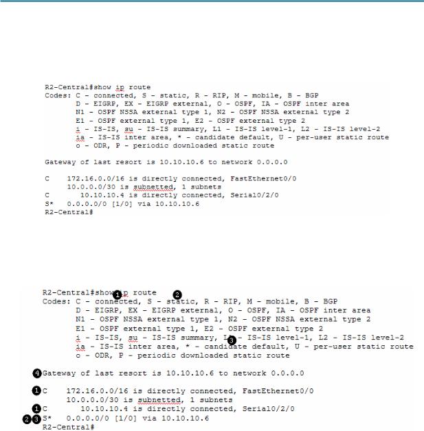
The route information displayed is much more detailed than the route information on a host computer. This is to be expected, because the job of a router is to route traffic between networks. The information required of this task, however, is not difficult to glean. Figure 2 shows the routing table for R2-Central.
Figure 2. Output of the Cisco IOS show ip route Command
The Codes section shown in Figure 3 provides an explanation for the symbols to the left of each route entry.
Figure 3. Explanation of Codes
C denotes directly connected networks and the interface that supports the connection.
S denotes a static route, which is manually entered by the Cisco network engineer.
Because the route is ”quad-zero,” it is a candidate default route.
If there is no other route in the routing table, use this gateway of last resort IP address to forward packets.
How is IP mask information displayed in a router routing table?
____________________________________________________________________________
____________________________________________________________________________
All contents are Copyright © 1992–2007 Cisco Systems, Inc. All rights reserved. This document is Cisco Public Information. |
Page 6 of 7 |

CCNA Exploration |
|
Network Fundamentals: OSI Network Layer |
Lab 5.5.1: Examining a Route |
What would the router do with packets destined to 192.168.254.254?
____________________________________________________________________________
____________________________________________________________________________
When finished examining the routing table, exit the router with the command exit <ENTER>. The telnet client will also close the connection with the telnet escape sequence <CTRL> ] and quit. Close the terminal window.
Task 4: Reflection
Two new Windows commands were used in this lab. The route command was used to view, delete, and add route information on the pod host computer.
The Windows Telnet client, telnet, was used to connect to a lab router, R2-Central. This technique will be used in other labs to connect to Cisco network devices.
The router routing table was examined with the Cisco IOS command show ip route. Routes for directly connected networks, statically assigned routes, and gateway of last resort information are displayed.
Task 5: Challenge
Other Cisco IOS commands can be used to view IP address information on a router. Similar to the Windows ipconfig command, the Cisco IOS command show ip interface brief will display IP address assignments.
R2-Central#show ip interface brief |
|
|
|
||
Interface |
IP-Address |
OK? Method |
Status |
Protocol |
|
|
|
|
|
|
|
FastEthernet0/0 |
172.16.255.254 |
YES manual |
up |
up |
|
FastEthernet0/1 |
unassigned |
YES unset |
administratively down down |
||
Serial0/2/0 |
10.10.10.5 |
YES manual |
up |
up |
|
Serial0/2/1 |
unassigned |
YES unset |
administratively down down |
||
R2-Central# |
|
|
|
|
|
Using Windows commands and the Cisco IOS commands in this lab, compare network information output. What was missing? What critical network information was similar?
____________________________________________________________________________
____________________________________________________________________________
Task 6: Clean Up
Unless directed otherwise by the instructor, turn off power to the host computers. Remove anything that was brought into the lab, and leave the room ready for the next class.
All contents are Copyright © 1992–2007 Cisco Systems, Inc. All rights reserved. This document is Cisco Public Information. |
Page 7 of 7 |