


Routing Configuration
Because of the large numbers of routing options and possible configurations, routings are most usefully loaded as presets, which can be accessed
by pressing and holding the PROGRAM key. In those cases where the factory-supplied routings are not sufficient, time may be saved by picking the nearest one and making such modifications as are required. The result can then be saved under a new name. For completeness, a description of each routing option follows.
All the individual routing pages are accessed from the main SETUP page.
Connecting real world inputs to the H8000FW
Different versions of the H8000FW support a wide range of possible inputs, as described in the chart below. Be aware that, as described above, when using either effects unit (DSP), the external inputs must be connected to the MAIN Inputs block. This limits the number of channels that can feed the effects units to eight, the number of inputs to the MAIN Inputs block. In many cases, external inputs may be connected to external outputs without this limitation, as described later.
|
Analog |
AES/EBU |
ADAT |
FireWire |
H8000 |
2 channels |
8 channels |
8 channels |
|
H8000A |
4 channels |
4 channels |
8 channels |
|
H8000FW |
4 channels |
12 channels |
8 channels |
16 channels |
|
|
|
|
|
CONFIGURING THE MAIN INPUTS
The MAIN Inputs block is used as a binding post to select the inputs that are to be fed to DSP A or DSP B. Each unit in the H8000FW series has a number of default inputs, which only connect to the corresponding input of the MAIN Inputs block as shown below:
The other inputs may be connected to any channel of the MAIN Inputs block.
See Further input options to select SPDIF 1&2 or Analog 1&2 on the H8000.
53
N Inputs channel |
H8000 input |
H8000A input |
H8000FW input |
1 |
AES/EBU 1 / SPDIF 1 |
Analog 1 |
Analog 1 |
2 |
AES/EBU 2 / SPDIF 2 |
Analog 2 |
Analog 2 |
3 |
AES/EBU 3 |
Analog 3 |
Analog 3 |
4 |
AES/EBU 4 |
Analog 4 |
Analog 4 |
5 |
AES/EBU 5 |
AES/EBU 1 / SPDIF 1 |
AES/EBU 1 / SPDIF 1 |
6 |
AES/EBU 6 |
AES/EBU 2 / SPDIF 2 |
AES/EBU 2 / SPDIF 2 |
7 |
AES/EBU 7 / Analog 1 |
AES/EBU 3 |
AES/EBU 3 |
8 |
AES/EBU 8 / Analog 2 |
AES/EBU 4 |
AES/EBU 4 |
in |
1 |
|
Analog |
2 |
|
3 |
||
|
||
|
4 |
|
in |
1 |
|
AES/EBU |
4 |
|
|
2 |
|
|
3 |
|
|
1 |
|
|
2 |
|
in |
3 |
|
4 |
||
ADAT |
||
5 |
||
|
||
|
6 |
|
|
7 |
|
|
8 |
Thus, using the H8000FW as an example, the fifth channel of MAIN Inputs (shown to the right of the inputs) may be connected to the first channel of AES/EBU in (the corresponding default input), or any channel of AES in, FireWire1 in or FireWire2 in or
ADAT in.
|
|
|
|
|
SP/DIF |
|
|
|
Analogin |
1 |
|
|
|
|
|
|
|
|
|
1 |
|
|
2 |
|
|
|
|||
|
|
|
|
|
opto |
|
|
|
|
|
|
|||
|
|
|
|
|
2 |
|
|
|
3 |
|
|
|
||
|
|
|
|
|
|
|
|
|
|
|
|
|||
|
|
|
SP/DIF |
|
SP/DIF |
|
|
|
|
4 |
|
|
|
|
|
|
|
1 |
1 |
|
|
inAES/EBU |
1 |
1 |
inMain |
1 |
|||
|
|
|
coax1 |
coax2 |
|
|
|
2 |
|
2 |
||||
|
|
|
2 |
2 |
|
|
|
2 |
|
|||||
|
|
|
|
|
|
|
|
|
|
3 |
3 |
|
3 |
|
|
|
|
|
|
|
|
|
|
|
4 |
|
4 |
||
|
|
|
|
|
|
|
|
|
|
4 |
|
|||
|
|
|
|
|
|
|
|
|
|
5 |
|
5 |
||
|
|
|
|
|
|
|
|
|
|
|
|
|||
|
|
|
|
11 |
|
|
|
|
|
|
6 |
|
6 |
|
|
|
|
|
|
1 |
|
|
|
|
7 |
|
7 |
||
|
|
|
|
12 |
|
|
1 |
|
|
|
||||
|
|
|
|
|
2 |
|
|
1 |
8 |
|
8 |
|||
|
|
|
|
13 |
FireWire1in |
|
2 |
|
|
|||||
|
|
|
AES in |
3 |
FireWire2in |
|
2 |
|
|
|
||||
|
|
|
14 |
3 |
|
|
|
|
||||||
|
|
|
4 |
ADATin |
3 |
|
|
|
||||||
|
|
|
17 |
6 |
|
|
|
|||||||
|
|
|
|
15 |
|
5 |
|
4 |
|
4 |
|
|
|
|
|
|
|
|
16 |
|
6 |
|
5 |
|
5 |
|
|
|
|
|
|
|
|
|
|
|
|
|
|
|
|
|||
|
|
|
|
18 |
|
7 |
|
7 |
|
6 |
|
|
|
|
1 |
|
1 |
|
|
8 |
|
|
7 |
|
|
|
|||
|
|
|
|
|
8 |
|
|
|
|
|||||
|
|
|
|
|
|
|
8 |
|
|
|
||||
2 |
|
2 |
|
|
|
|
|
|
|
|
|
|
||
3 |
in |
3 |
|
|
|
|
|
|
|
|
|
|
|
|
4 |
4 |
|
|
|
|
|
|
|
|
|
|
|
||
Main |
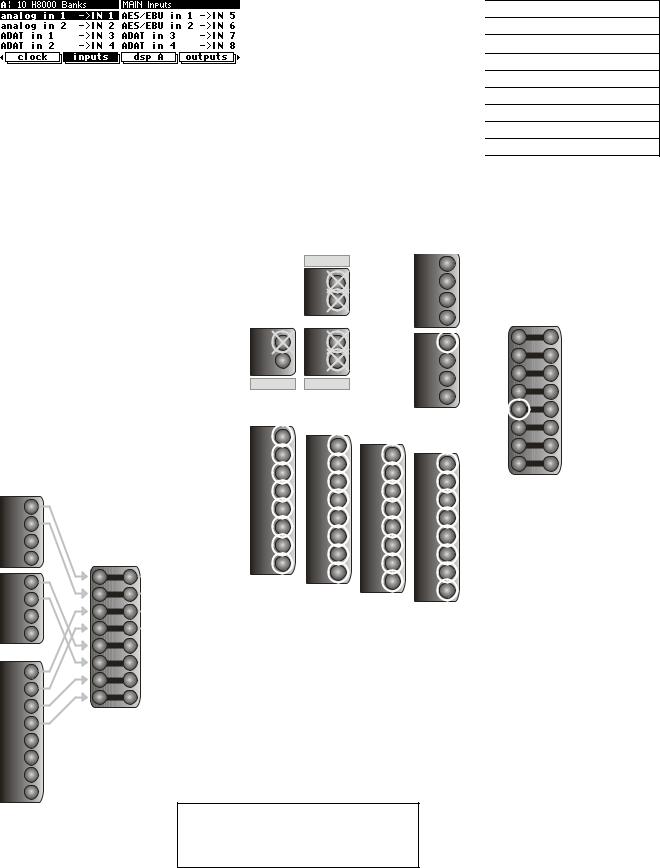
The MAIN Inputs block is configured using the inputs menu under the |
|||||||||||||
5 |
5 |
|||||||||||||
|
||||||||||||||
6 |
|
6 |
SETUP key. This example shows: |
|
|
|
|
|
|
|
||||
7 |
|
7 |
Analog in 1 and 2 connected to MAIN Inputs 1 and 2 |
|||||||||||
8 |
|
8 |
||||||||||||
ADAT in 1 and 2 connected to MAIN Inputs 3 and 4
AES/EBU in 1 and 2 connected to MAIN Inputs 5 and 6
ADAT in 1 and 2 connected to MAIN Inputs 7 and 8
54
CONFIGURING THE DSP INPUT SOURCES
Any DSP input may be fed from any of the MAIN Inputs block outputs, or from any output of either DSP. Note that the MAIN Inputs block’s channel names change to show what is connected to it – in the example below it is connected to Analog in 1-4 and AES/EBU in 1-4.
in |
1 |
|
Analog |
2 |
|
3 |
||
|
||
|
4 |
|
in |
1 |
|
AES/EBU |
4 |
|
|
2 |
|
|
3 |
|
|
1 |
|
|
2 |
|
in |
3 |
|
4 |
||
ADAT |
||
5 |
||
|
||
|
6 |
|
|
7 |
|
|
8 |
1
2
3
4
5
6
7
8
 Main in


1
2
3
4
5
6
7
8
11
22
33
4DSP 4
5 A 5
66
77
8 8
11
22
33
4DSP 4
5 B 5
66
77
8 8
CONFIGURING THE MAIN OUTPUTS
The main outputs may be fed from any DSP output or from any of the MAIN Inputs. Up to two signals may be connected to each output. There are two pages - one for channels 1-4, feeding the main Analog outputs as shown above, and another for channels 5-8, feeding the main AES/EBU outputs.
Here we have DSP A 1-4 and DSP B 1-4 feeding Main output channels 1-4 (Analog). This means that, for example DSP A out 1 and DSP B out 1 are mixed together to feed Main out 1.
11
22
33
4DSP 4
5 A 5
66
77
8 8
11
22
33
4DSP 4
5 B 5
66
77
8 8
1
2
3
4
5
6
7
8
 Main out

1
2
3
4
5
6
7
8
55
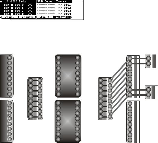
Here we have DSP A 5-8 feeding MAIN Output channels 5-8 (Digital)
|
1 |
|
in |
2 |
|
3 |
||
AES/EBU |
||
6 |
||
|
4 |
|
|
5 |
|
|
7 |
|
|
8 |
|
|
1 |
|
|
2 |
|
in |
3 |
|
4 |
||
ADAT |
||
5 |
||
|
||
|
6 |
|
|
7 |
|
|
8 |
1
2
3
4
5
6
7
8
 Main in


1
2
3
4
5
6
7
8
1 |
1 |
2 |
2 |
33
4DSP 4
5 |
A 5 |
6 |
6 |
77
88
11
22
33
4DSP 4
5 B 5
66
77
8 8
56
1
2
3
4
5
6
7
8
 Main out


1
2
3
4
5
6
7
8
1
2
3
4
5
6
7
8
1
2
3
4
5
6
7
8


 ADAT out AES/EBU out


1
2
1
2


 SP/DIF


 Analog


