

Будова перевірка та дослідження South NTS 352R(L) / MANUAL ET SOUTH NTS350R ING
.pdf
|
|
|
|
|
|
|
|
|
|
|
|
|
|
|
|
|
AREA |
|
|
|
|
Press F1 AREA key. |
|
F1 |
|
F1 FILE DATA |
|
|
|
|||
|
|
F2 MEASUREMENT |
|
|
||||||
|
|
|
|
|
|
|
|
|||
|
|
|
|
|
|
|
|
|
|
|
|
|
|
|
|
|
|
|
|
|
|
|
|
|
|
|
|
AREA |
|
|
|
|
Press F2 MEASUREMENT key |
F2 |
|
F1 USE G. F. |
|
|
|
||||
|
F2 DON’T USE |
|
|
|
||||||
|
|
|
|
|
|
|
|
|
||
|
|
|
|
|
|
|
|
|
|
|
|
|
|
|
|
|
|
|
|
|
|
Press F1 or F2 key to select using |
|
|
AREA |
|
|
0000 |
|
|||
|
|
|
|
|
|
|
||||
GRID FACTOR or not. |
|
|
F2 |
|
|
|
m.sq |
|
||
|
|
|
|
|
|
|
|
|||
Example: F2 DON’T USE |
|
|
|
MEAS |
--- |
UNIT |
--- |
|
||
|
|
|
|
|
|
|
||||
|
|
|
|
|
|
|
|
|
|
|
|
|
|
|
|
|
|
|
|
|
|
|
|
|
|
|
|
N*[n] |
|
<< |
m |
|
Collimate a prism and press theF1 |
Collimate P |
|
E : |
|
|
m |
|
|||
MEAS key. Measuring stars*1 |
F1 |
|
Z : |
|
|
m |
|
|||
|
|
|
|
|
|
>Measuring…… |
|
|
|
|
|
|
|
|
|
|
|
|
|
|
|
|
|
|
|
|
|
|
|
|
|
|
Collimate a |
prism |
and |
pressF1 |
|
|
AREA |
|
|
0003 |
|
|
|
|
|
|
|
|
||||
MEAS key.When 3 points are set, the |
Collimate |
|
|
11 144m.sq |
|
|||||
|
|
|
|
|
|
|||||
area surrounded |
by |
the |
points is |
F1 |
|
MEAS |
--- |
UNIT |
--- |
|
|
|
|
|
|
|
|
||||
calculated and the result will be shown. |
|
|
|
|
|
|
|
|||
|
|
|
|
|
|
|
||||
|
|
|
|
|
|
|
|
|||
*1 Measurement is N-time measurement mode. |
|
|
|
|
|
|||||
*To change the display unit |
|
|
|
|
|
|
|
|
||
It is possible to change the display area unit.
|
Operation procedure |
|
Operation |
|
|
Display |
|
|
|
|
|
|
|
|
|
AREA |
|
|
0003 |
|
|
|
|
|
|
|
|
|
100 000m.sq |
|
|
|
|
|
|
|
|
MEAS |
--- |
UNIT |
--- |
|
|
|
|
|
|
|
|
|
|
|
|
|
|
|
|
|
|
AREA |
|
|
0003 |
|
|
|
Press F3 UNIT key. |
|
F3 |
|
|
|
100 000m.sq |
|
|
|
|
|
|
|
|
|
|
|
|
||
|
|
|
|
|
m.sq |
ha |
ft.sq |
acre |
|
|
|
|
|
|
|
|
|
|
|
|
|
|
|
|
|
|
|
|
|
|
|
|
|
|
|
|
|
|
|
|
67 |
|
|
PDF "pdfFactory Pro" |
www.fineprint.com.cn |
|
|
|
||||||
Press |
F1 to F4 key to select a |
|
|
|
|
|
AREA |
|
|
0003 |
|
|
|
|
|
|
|
|
|
0.010 ha |
|
||||
unit. *1 |
|
|
|
|
F2 |
|
|
|
|
|
||
|
|
|
|
|
|
|
|
|
|
|
||
|
|
|
|
|
|
|
|
|
|
|
|
|
Example: |
F2 |
ha |
|
|
|
|
|
MEAS |
--- |
UNIT |
--- |
|
|
|
|
|
|
|
|
|
|
||||
|
|
|
|
|
||||||||
*1 m.sq:square meter ha:hectare |
ft.sq:square feet |
acre:acre |
|
|
||||||||
|
|
|
|
|
|
|
|
|
|
|
|
|
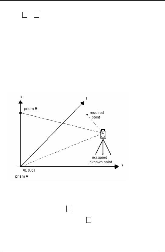
11.1.5 Point to Line Measurement
This mode is used to obtain the coordinate data with the origin point A (0,0,0) and the line AB as N axis. Place the 2 prisms at the A and B on the line, and place the instrument at unknown point C. After measuring the 2 prisms, the coordinate and the direction angle of the instrument will be calculated and recorded.
|
|
|
Operation |
|
Display |
|
|
||
Operation procedure |
|
|
|
|
|
||||
|
|
|
|
|
|
|
|
|
|
|
|
|
|
|
|
|
MENU |
2 / 3 |
|
|
|
|
|
MENU |
|
|
|
||
|
|
|
|
|
|
|
|
|
|
After pressing |
MENU |
key, press F4 |
|
|
|
|
F1 PROGRAMS |
|
|
(p↓)key to get the menu on page2. |
|
|
F2 GRID FACTOR |
|
|
||||
|
|
|
|
F4 |
|
F3 ILLUMINATION |
P1↓ |
|
|
|
|
|
|
|
|
|
|
||
|
|
|
|
|
|
|
|
|
|
68
PDF "pdfFactory Pro" www.fineprint.com.cn

|
|
|
|
|
|
|
|
|
|
|
|
|
|
PROGRAMS |
|
1 / 2 |
|
|
|
|
Press the F1 key |
F1 |
|
F1 REM |
|
|
|
|
|
|
|
F2 MLM |
|
|
|
|
|||
|
|
|
|
|
|
|
|
||
|
|
|
|
F3 Z COORD. |
P1↓ |
|
|
||
|
|
|
|
|
|
|
|
|
|
|
|
|
|
|
|
|
|
|
|
|
|
|
|
PROGRAMS |
|
2 / 2 |
|
|
|
|
Press F4 P1↓ key |
F4 |
|
F1 AREA |
|
|
|
|
|
|
|
F2 POINT TO LINE |
|
|
|||||
|
|
|
|
|
|
||||
|
|
|
|
|
|
|
P1↓ |
|
|
|
|
|
|
|
|
|
|||
|
|
|
|
|
|
|
|
|
|
|
|
|
|
INSRUMENT HEIGHT |
|
|
|||
|
Press F2 POINT TO LINE key |
F2 |
|
INPUT |
|
|
|
|
|
|
|
INS.HT |
|
|
0.000 m |
|
|
||
|
|
|
|
|
|
|
|
||
|
|
|
|
INPUT |
--- |
-- |
ENTER |
|
|
|
|
|
|
|
|
|
|||
|
|
|
|
|
|
|
|
|
|
|
Press F1 INPUT key and enter |
F1 |
|
REFECTOR HEIGHT |
|
|
|||
|
|
INPUT |
|
|
|
|
|
||
|
instrument height. |
Enter INS.HT |
|
|
|
|
|
|
|
|
|
R.HT |
|
0.000 m |
|
|
|||
|
Press F4 |
F4 |
|
|
|
|
|||
|
|
INPUT |
--- |
-- |
ENTER |
|
|
||
|
|
|
|
|
|
||||
|
|
|
|
|
|
|
|
|
|
|
|
|
|
|
|
|
|
|
|
|
Press F1 INPUT key and enter |
F1 |
|
POINT TO LINE |
|
|
|
|
|
|
|
MEAS.P1 |
|
|
|
|
|
||
|
reflector A (P1) height |
Enter R. HT |
|
|
|
|
|
|
|
|
|
HD |
|
|
|
|
|
||
|
Press F4 |
F4 |
|
|
|
|
|
|
|
|
|
>Sight |
|
[YES] [NO] |
|
|
|||
|
|
|
|
|
|
|
|||
|
|
|
|
|
|
|
|
|
|
|
|
|
|
|
|
|
|
|
|
|
|
|
|
POINT TO LINE |
|
|
|
|
|
|
Collimate prism P1 Origin and |
|
|
MEAS.P1 |
|
|
|
|
|
|
|
|
HD *[n] |
|
|
<< m |
|
|
|
|
press F3 YES key. |
|
|
|
|
|
|
||
|
|
|
>Measuring …… |
|
|
|
|||
|
Measuring starts.*1 |
Collimate P1 |
|
|
|
|
|||
|
|
|
|
|
|
|
|
||
|
|
|
|
|
|
|
|||
|
|
F3 |
|
|
|
|
|
|
|
|
Input display of reflector B (P2) height |
|
|
REFECTOR HEIGHT |
|
|
|||
|
|
|
INPUT |
|
|
|
|
|
|
|
will be shown. |
|
|
|
|
|
|
|
|
|
|
|
R.HT |
|
0.000 m |
|
|
||
|
|
|
|
|
|
|
|||
|
|
|
|
INPUT |
--- |
-- |
ENTER |
|
|
|
|
|
|
|
|
|
|
|
|
|
|
|
|
|
|
|
|
|
|
|
Press F1 INPUT key and enter |
F1 |
|
POINT TO LINE |
|
|
|
|
|
|
|
MEAS. P2 |
|
|
|
|
|||
|
|
|
|
|
|
|
|
||
|
reflector B P2 height |
Enter R.HT |
|
HD |
|
|
|
|
|
|
Press F4 |
F4 |
|
>Sight |
|
[YES] [NO] |
|
|
|
|
|
|
|
|
|
|
|
|
|
|
|
|
|
|
|
|
|
|
|
|
|
|
|
|
|
|
|
|
|
69
PDF "pdfFactory Pro" www.fineprint.com.cn

|
|
|
|
|
|
|
|
|
|
|
Collimate prism B (P2) and press |
|
|
|
POINT TO LINE |
|
|
|
|
||
|
|
|
MEAS.P2 |
|
|
|
|
|||
F3 YES . |
|
|
|
|
|
|
|
|
||
|
|
|
|
HD *[n] |
|
|
<< m |
|
||
|
|
|
|
|
|
|
|
|||
Measuring starts*1 |
|
|
Collimate P2 |
|
>Measuring…… |
|
set |
|
||
The coordinate data and direction |
|
|
|
|
|
|
||||
|
F3 |
|
DIST. P1-P2 |
1/2 |
|
|||||
angle of the instrument |
is caculated |
|
|
|
dHD: |
3.254 |
m |
|
|
|
|
|
|
dVD: |
0.214 |
m |
|
|
|||
and recorded. |
|
|
|
|
|
|
||||
|
|
|
|
NEZ |
S.CO |
--- |
|
P1↓ |
|
|
|
|
|
|
|
|
|
||||
|
|
|
|
|
|
|
|
|
|
|
|
|
|
|
|
|
|
|
|
|
|
Press F1 NEZ key to measure |
|
|
|
N |
|
0.000 |
m |
|
||
|
|
|
E : |
|
0.000 |
m |
|
|||
other points. |
|
|
|
|
Z : |
|
0.000 |
m |
|
|
|
|
|
|
|
EXIT |
--- |
HT |
MEAS |
|
|
|
|
|
|
|
|
|
|
|
||
|
|
|
|
|
>Measuring …… |
|
|
|
||
|
|
|
|
|
|
|
|
|
|
|
Collimate prism press F4 MEAS |
|
|
|
|
|
|
|
|
|
|
|
|
|
|
|
3.554 |
m |
|
|||
|
|
|
|
|
N |
|
|
|||
key. |
|
|
Collimate P |
|
E : |
|
5.254 |
m |
|
|
Measuring starts *4 |
|
|
F4 |
|
Z : |
|
0.000 |
m |
|
|
|
|
|
EXIT |
--- |
HT |
MEAS |
|
|||
The result will be shown.*5 |
|
|
|
|
||||||
|
|
|
|
|
|
|
|
|
||
|
|
|
|
|
|
|
|
|||
|
|
|
|
|
|
|
|
|
||
*1 Measurement is N-time measurement mode. |
|
|
|
|
|
|
||||
*2 ) Press F4 (P1↓ )key |
to show dSD |
|
|
|
|
|
|
|
|
|
*3) Press F2 (S.CO) key to show the new occupied data. |
|
|
|
|
|
|
||||
*4) Measurement is N-time measurement mode. |
|
|
|
|
|
|
||||
*5) To return to previous mode, press F1 (EXIT) key. |
|
|
|
|
|
|
||||
11.2 Setting the GRID FACTOR
GRID FACTOR can be reset in this menu mode.
For more information, refer to Section 13.2.1 “Setting the GRID FACTOR”
Operation procedure |
Operation |
|
Display |
|
|
||||
After pressing the |
|
key, |
|
|
|
|
MENU |
2 / 3 |
|
MENU |
|
MENU |
|
|
|
||||
|
|
|
F1 PROGRAMS |
|
|
||||
press the F4 (p↓) key to get the |
|
|
|
|
|
|
|||
|
|
|
|
F2 GRID FACTOR |
|
|
|||
menu on page 2. |
|
F4 |
|
|
|
||||
|
|
F3 ILLUMINATION |
P1↓ |
|
|||||
|
|
|
|
|
|
|
|
||
|
|
|
|
|
|
|
|
|
|
70
PDF "pdfFactory Pro" www.fineprint.com.cn

|
|
|
|
|
|
|
|
|
|
|
|
|
GRID |
FACTOR |
|
|
|
|
|
|
|
|
|
|
|
|
|
|
|
|
|
|
|
|
|
` Press the |
F2 |
(GRID |
|
|
|
|
= 0.998823 |
|
|
|
|||||||
|
F2 |
|
|
|
|
|
|||||||||||
FACTOR) key |
|
|
|
>MODIFY? |
[YES] [NO] |
|
|||||||||||
|
|
|
|
|
|||||||||||||
|
|
|
|
|
|||||||||||||
|
|
|
|
|
|
|
|
|
|
|
|
|
|
||||
|
|
|
|
|
|
|
|
|
|
|
|
|
|
|
|
|
|
|
|
|
|
|
|
|
|
|
|
|
|
|
GRID |
FACTOR |
|
|
|
Press the |
|
|
|
(YES) key |
|
|
|
|
ELEV.-> |
1000m |
|
|
|||||
F3 |
|
F3 |
|
|
|
|
|||||||||||
|
|
|
SCALE: 0.999000 |
|
|
||||||||||||
|
|
|
|
|
|
|
|
|
|
|
|
|
|
|
|||
|
|
|
|
|
|
|
|
|
|
|
|
|
INPUT |
--- |
--- |
ENTER |
|
|
|
|
|
|
|
|
|
|
|
|
|
|
|
|
|
|
|
Press the |
|
|
(INPUT)key and |
|
|
|
|
GRID |
FACTOR |
|
|
||||||
F1 |
|
F1 |
|
|
|
|
|||||||||||
|
|
|
ELEV.->2000m |
|
|
||||||||||||
enter Elevation *1) |
Enter ELEV |
|
|
|
|||||||||||||
|
SCALE:-1.001000 |
|
|
||||||||||||||
Press the |
|
|
(ENT) key |
|
|
|
|
|
|
||||||||
F4 |
|
F4 |
|
|
|
|
|||||||||||
|
|
|
INPUT |
--- |
--- |
ENTER |
|
||||||||||
|
|
|
|
|
|
|
|
|
|
|
|
|
|
||||
|
|
|
|
|
|
|
|
|
|
|
|
|
|
||||
|
|
|
|
|
|
|
|
|
|
||||||||
Enter Scale Factor in the same |
|
|
|
|
|
|
|
|
|
||||||||
|
|
|
|
GRID |
FACTOR |
|
|
||||||||||
way Grid Factor is displayed for |
|
F1 |
|
|
|
|
|||||||||||
|
|
|
= 1.000685 |
|
|
|
|||||||||||
|
|
|
|
|
|
|
|||||||||||
Enter SCALE |
|
|
|
|
|||||||||||||
|
|
|
|
|
|
|
|
|
|
|
|
|
|
|
|||
1 to 2 second and display return |
|
|
|
|
|
|
|
|
|||||||||
|
F4 |
|
|
|
|
|
|
|
|||||||||
to menu. |
|
|
|
|
|
|
|
|
|
||||||||
|
|
|
|
|
|
|
|
|
|||||||||
|
|
|
|
|
|
|
|
|
|||||||||
*1 Refer to Section 5.8 “How to Enter Alphanumeric characters” |
|
|
|
|
|||||||||||||
Input Range: Elevation : -9999 to +9999m -32.805 to 32.805ft,ft+in |
|
|
|||||||||||||||
Scale Factor: 0.990000 to 1.010000 |
|
|
|
|
|
||||||||||||
11.3 Setting Illumination of Display and Cross Hairs
Setting ON/OFF for illumination of display (LCD) and reticle.
Example: illumination ON.
Operation procedure |
Operation |
|
Display |
|
|
||||
After pressing the |
|
key, |
|
|
|
|
MENU |
2 / 3 |
|
MENU |
|
MENU |
|
|
|
||||
|
|
|
F1 PROGRAMS |
|
|
||||
press the F4 (p↓) key to get the |
|
|
|
|
|
|
|||
|
|
|
|
F2 GRID FACTOR |
|
|
|||
menu on page 2. |
|
F4 |
|
|
|
||||
|
|
F3 ILLUMINATION |
P1↓ |
|
|||||
|
|
|
|
|
|
|
|
||
|
|
|
|
|
|
|
|
|
|
|
|
|
|
|
|
|
ILLUMINATION |
[OFF ] |
|
Press the F3 key |
|
F3 |
|
F1 ON |
|
|
|||
The data previously set is shown |
|
|
F2 OFF |
|
|
||||
|
|
|
|
|
|
||||
|
|
|
|
|
|
|
|
|
|
71
PDF "pdfFactory Pro" www.fineprint.com.cn

|
|
|
|
|
|
|
|
|
ILLUMINATION |
[ON] |
|
Press the |
|
(ON) key |
|
|
|
|
|
|
F1 ON |
|
|
F1 |
|
|
|
F1 |
|
|
|
|
|||
|
|
|
F2 OFF |
|
|
||||||
|
|
|
|
|
|
|
|
|
|
|
|
|
|
|
|
|
|
|
|
||||
To return to previous mode, press the |
ESC |
key |
|
|
|
||||||
72
PDF "pdfFactory Pro" www.fineprint.com.cn
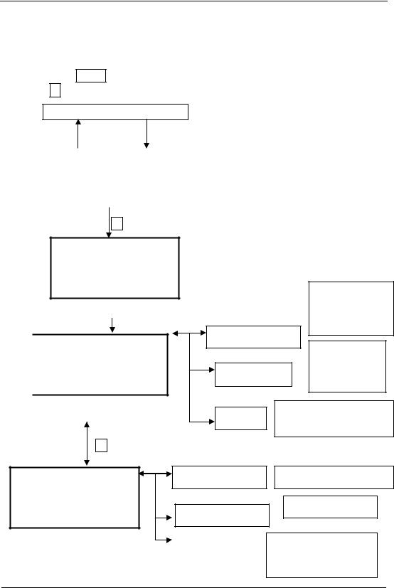
12. DATA COLLECTION
Data collect menu operation:
By pressing the MENU key, the instrument will be in MENU 1/3 mode.
Press the F1 (DATA COLLECT) key, the menu of data collect 1/2 will be shown.
Normal measurement mode
ESC |
|
|
MENU |
|
|
|
|
||
MENU |
1 / 3 |
|
||
F1 DATA COLLECT |
|
|
|
|
F2 LAYOUT |
|
|
|
|
F3 MEMORY MGR. |
|
P↓ |
|
|
|
|
|
|
|
F1
SELECT A FILE
FN ___________
INPUT LIST --- ENTER
|
|
Set file |
|
|
DATA COLLECT |
1 / 2 |
|
|
|||
|
F1 OCC . PT# |
INPUT |
|
|
F2 BACKSIGHT |
||
|
F3 FS / SS |
P↓ |
|
|
Data Collection Menu 1 / 2 |
||
|
|||
|
|
F4 |
|
DATA COLLECT |
2 / 2 |
||
F1 SELECT |
A FILE |
||
F2 PCODE |
INPUT |
|
|
F3 CONFIG. |
|
P↓ |
|
OCC . PT# INPUT
BACKSIGHT
Setting occupied point refer to 12.2.3.
Set backsight point refer to 12.2.3
FS / SS
SELECT A FILE
PCODE INPUT
Excuting data collection, refer to 12.3
Selecting coordinare file
Refer to 12.4
Set data collection parameter,refer to 12.5
73
PDF "pdfFactory Pro" www.fineprint.com.cn

NTS-350R is able to store the measured data into the internal memory
The internal memory is shared by the measured data and the coordinate data files.
Measured data:
The collected data is memorized into files.
The number of measurement points:
(in case of using the internal memory in layout mode) Max. 3500 points
Because the internal memory covers both data collection mode and layout mode, the
number of measurement points will be decreased when the layout mode is used. For the internal memory, refer to Chapter 11“Memory Management Mode”.
1) When turning off the power, ensure that you are in the main menu screen or main angle measurement mode. This ensures completion of the memory access process and avoids possible damage to the stored data.
2 It is recommended for safety to charge the battery (BT-52QA)beforehand and prepare fully charged spare batteries.
12.1 Operation procedure
1 Select Data Collection File to save data in it.
* When saving the data, you should select Parameter Setting at first, and select “NO” in “Only save coordinate data or not”.
2 Select Coordinate Data File so that you can use Occupied Point coordinate data and Backsigh coordinate data. (If coordinate data of known point is not necessary for use , bypass this step)
3 Set Occupied Point includeing Instrument Height, Point Number and Coordinat. 4 Set Backsight Point, Direction and Azimuth.
5 Start collecting and save data.
12.2 Preparation
12.2.1 Selecting a File for Data Collection
A file used by data collection mode must be selected at first.
Select a file before beginning data collection mode because selection screen of a file is displayed. And a selection from data collection menu is possible in the mode.
74
PDF "pdfFactory Pro" www.fineprint.com.cn

Operation procedure |
Operation |
|
|
Display |
|
|
|
|
|
|
|
|
|
|
|
|
|
|
MENU |
|
|
1 / 3 |
|
|
|
|
F1 DATA COLLECT |
|
|||
|
|
|
F2 LAYOUT |
|
|
|
|
|
|
|
F3 MEMORY |
MGR. P↓ |
|
||
|
|
|
|
|
|
||
|
|
|
|
|
|
||
|
|
|
|
|
|
|
|
Press F1 (DATA COLLECT) key from |
|
|
SELECT A FILE |
|
|
||
F1 |
|
FN ___________ |
|
|
|||
menu 1/3. |
|
|
|
|
|
|
|
|
|
|
|
|
|
|
|
|
|
|
INPUT |
LIST |
--- |
ENTER |
|
|
|
|
|
|
|
|
|
|
|
|
SOUDATA |
|
/M0123 |
|
|
Press F2 (LIST)key to display the list |
F2 |
|
->*LIFDATA |
|
/M0234 |
|
|
of file *1 |
|
DIEDATA |
|
/M0355 |
|
||
|
|
|
|
||||
|
|
|
--- |
SRCH |
--- |
ENTER |
|
|
|
|
|
|
|
|
|
|
|
|
|
|
|
|
|
|
|
|
LIFDATA |
|
/M0234 |
|
|
Scroll file list by pressing [▼] or |
[▲]or[▼] |
|
DIEDATA |
|
/M0355 |
|
|
[▲]key and select a file to use *2 3 |
|
->KLSDATA |
|
/M0038 |
|
||
|
|
|
--- |
SRCH |
--- |
ENTER |
|
|
|
|
|
|
|
|
|
|
|
|
|
|
|
|
|
Press F4 (ENTER) key |
|
|
DATA |
COLLECT |
1 / 2 |
|
|
|
|
F1 OCC . PT# |
INPUT |
|
|||
The file will be set and data collect 1/2 |
F4 |
|
|
||||
|
F2 BACKSIGHT |
|
|
||||
menu will be shown. |
|
|
|
|
|||
|
|
F3 FS / SS |
|
P↓ |
|
||
|
|
|
|
|
|||
|
|
|
|
|
|
|
|
*1) If you want to make a new file or input file name directly, press F1 (INPUT) key and enter a file name.
2) When a file has been selected already, ‘*’ mark is indicated on left of current file name
*3) Data in a file shown with arrow can be searched by pressing F2 (SRCH) key. It is possible to select a file from DATA COLLECT 2/2 menu in the same way.
12.2.2 Selecting a Coordinate File for Data Collection
When coordinate data in a coordinate data file are used for occupied point or backsight point, select a coordinate file from the data collect menu 2/2 beforehand.
75
PDF "pdfFactory Pro" www.fineprint.com.cn

Operation procedure |
Operation |
|
|
|
Display |
|
|
|
|
|
|
|
|
|
|
|
|
|
|
|
DATA |
COLLECT |
2 / 2 |
|
||
Press the F1 (SELECT A FILE) key from |
|
|
|
SELECT |
A |
FILE |
|
|
|
F1 |
|
F1 |
|
||||
DATA COLLECT menu 2/2. |
|
|
PCODE |
INPUT |
|
|||
|
|
|
||||||
|
|
|
F2 |
|
||||
|
|
|
F3 CONFIG. |
|
P↓ |
|
||
|
|
|
|
|
|
|
||
|
|
|
|
|
|
|
|
|
|
|
|
SELECT |
A FILE |
2 / 2 |
|
||
Press the F2 (COORD DATA) key |
F2 |
|
F1 MEAS . DATA |
|
|
|||
|
F2 COORD . DATA |
|
||||||
|
|
|
|
|||||
|
|
|
|
|
|
|
||
|
|
|
|
|
|
|
||
Select a coordinate file in the same |
|
|
SELECT |
A FILE |
|
|
||
manner as Section 9.2.1 “Selecting a File |
|
|
FN ___________ |
|
|
|||
|
|
|
|
|
|
|
|
|
for Data Collection” |
|
|
INPUT |
LIST |
--- |
ENTER |
|
|
|
|
|
|
|
|
|
|
|
12.2.3 Occupied Point and Backsight Point
The occupied point and direction angle in the data collect mode are linked with the
occupied point and it is possible to set or change the occupied point and direction angle from
the data collect mode.
Occupied point can be set by two setting methods as follow
1)Setting from the coordinate data stored in the internal memory
2)Direct key input
The following three setting methods for backsinght point can be selected:
1)Setting from the coordinate stored in the internal memory
2)Direct key input of coordinate data
3)Direct key input of setting angle
Note: See Chapter 11.4 “Coordinate Data Direct Key Input” and 11.7.2 “Loading data”. Example for setting the occupied point:
In case of setting occupied point from the coordinate data stored in the internal memory.
76
PDF "pdfFactory Pro" www.fineprint.com.cn