


This chapter will introduce you to the basic technology that you need to become familiar with for a thorough understanding of MPLS. I’ll start with a quick review of traditional service provider networks and the challenges of managing them. After that review, I’ll introduce you to the basics of MPLS architecture and operation. You’ll need a good understanding of the basic MPLS concepts to understand the material in later chapters and to succeed on the MPLS exam.
As an instructor of MPLS, I’ve found that the best way for someone to learn MPLS is to simply jump right in. This chapter will introduce you to some of the major MPLS topics—it’s the baptism by fire into the world of MPLS. Let’s get to it.
Service Provider Networks
We’re going to begin discussing MPLS not with the technology itself, but with many of the problems it is designed to fix in service provider networks.
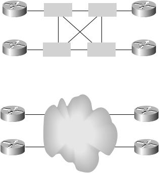
To illustrate some of the problems that are experienced by service providers, let’s start with a simple service provider network. Figure 1.1 shows four POPs (points of presence): Atlanta, Miami, Orlando, and Raleigh. At each of these POPs, the routers are connected to ATM switches that are fully meshed, creating the core of the service provider network.
Another way to represent the service provider network is to show the POP locations connected to a cloud, as illustrated in Figure 1.2. This representation of the service provider network in Figure 1.2 is logical, compared to the physical topology in Figure 1.1. The cloud is a way to demonstrate the problem faced when integrating ATMand IP-based routers.
Copyright ©2002 SYBEX, Inc., Alameda, CA |
www.sybex.com |
Service Provider Networks 3
IP and ATM were developed separately and without much regard for each other. The ATM switches are only concerned with moving traffic based on VPI/VCI values of which the IP-based POP routers are unaware. IP-based POP routers are Layer 3 devices, concerned with forwarding packets based on information contained in the packet, of which the ATM switches are unaware.
F I G U R E 1 . 1 Service provider physical topology
|
ATM |
|
ATM |
|
|
|
|
|
|
|
|
Raleigh POP |
|
|
|
Atlanta POP |
|
|
|
|
|
|
|
|
ATM |
|
ATM |
|
|
|
|
|
|
|
|
Miami POP |
|
|
|
Orlando POP |
|
F I G U R E 1 . 2 Service provider logical topology
Scalability
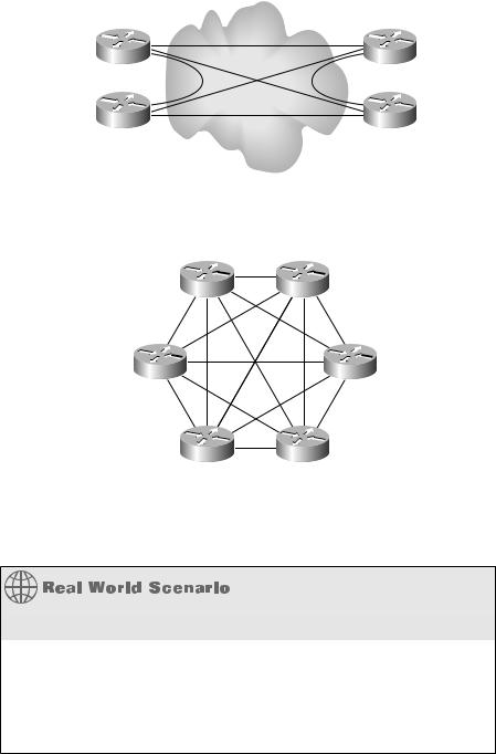
Another problem experienced by service providers is scalability. To allow for maximum redundancy and optimum routing, a full mesh of virtual circuits (VCs) must be created, resulting in an overlay. In Figure 1.3, the four POP routers are connected together with a full mesh of VCs. Notice that for four POP routers, six VCs are required.
If two more POP routers are added, as shown in Figure 1.4, a total of 15 VCs are required to provide full-mesh connectivity.
Copyright ©2002 SYBEX, Inc., Alameda, CA |
www.sybex.com |
4 Chapter 1 An Introduction to MPLS
F I G U R E 1 . 3 Full mesh with six virtual circuits
F I G U R E 1 . 4 Full mesh with 15 virtual circuits
POP |
POP |
POP |
POP |
POP |
POP |
As more and more POP routers are added to this core, more and more VCs will be required to provide a full mesh.
The Overlay Model
The big problem with an overlay model, in which the routers are connected in a full mesh through virtual circuits, is that officially it is not scalable. Depending on who you talk to, either an ATM overlay is scalable or an ATM overlay is not scalable. Since this is an exam preparation guide, the official ruling is that an ATM overlay is not scalable.
Copyright ©2002 SYBEX, Inc., Alameda, CA |
www.sybex.com |

Service Provider Networks 5
To illustrate, if you assume that the virtual circuits in question are bidirectional in nature, the following formula calculates the number of virtual circuits required: n(n–1)/2, where n is the number of routers. So, if you have four routers and you want full-mesh connectivity, the math to determine the number of required VCs is as follows:
4(4-1)/2
4(3)/2
12/2
6
If there are six routers connected together, the number of required VCs is 15:
6(6-1)/2
6(5)/2
30/2
15
As you add more routers, the number of VCs required to implement a full mesh increases exponentially. If there are 100 routers, the total number of bi-directional VCs required is calculated as follows:
100(100-1)/2
100(99)/2
9900/2
4500
Not only are there scalability problems with the number of VCs required to implement a full mesh, but there are also scalability problems associated with the routing protocols in use in the network. As more and more VCs are created, more and more routers must form adjacencies with one another to ensure redundancy. All of these routers must exchange routing table updates with every router, thus creating a great deal of traffic that is merely updating routing tables. This excessive traffic can utilize significant resources on the routers and slow them down.
Copyright ©2002 SYBEX, Inc., Alameda, CA |
www.sybex.com |