

BMW 3 & 5 Series Haynes Manual
.pdf9•12 Braking system
and push it through until the forward end comes out at the handbrake lever.
8 Insert the cable conduit through the backplate, and attach the rear end of the cable to the handbrake lever (rear drum models) or the actuator (rear disc models). Make sure you don’t kink the cable while connecting it.
9Refit the cable conduit to the clips on the back of the trailing arm.
10On rear drum models, refit the brake shoes and drum (see Section 6). On rear disc models, refit the handbrake shoes and actuator (see Section 12) and the rear brake disc (see Section 5).
11Lower the vehicle, and refit the adjusting nut at the handbrake lever. Adjust the handbrake cable (see Section 11) and refit the handbrake lever boot.
11 Handbrake - adjustment |
2 |
|
|
Rear drum brake models
Note: Adjustment of the handbrake cable(s) on models with rear drum brakes should only be necessary when you renew a cable or detach if from the rear brake assembly for some reason. Failure of the handbrake system to hold the vehicle usually indicates worn brake shoes or a faulty self-adjusting mechanism.
1Raise the rear of the vehicle, and place it securely on axle stands.
2Fully release the handbrake lever, then apply the brakes firmly several times with the footbrake pedal.
3Pull the handbrake lever up five clicks.
4Tighten or loosen the adjusting nuts by equal amounts until the rear brake shoes just begin to drag on the brake drum. You should feel the same amount of resistance at both wheels when you rotate them.
5Release the handbrake lever, and verify that the wheels rotate freely. If they don’t, readjust them.
Raise the vehicle and place it securely on axle stands.
9Remove the bolt you loosened in each rear wheel. Turn the wheel until, using a torch, you can see the adjuster starwheel through the bolt hole.
10Turn the adjuster - clockwise to expand the shoes, anti-clockwise to retract them - until the brake shoes just contact the brake drum (see illustration 5.6d). Back off the brake shoes so the wheel spins freely (three to four teeth on the adjuster). Note: If the adjuster starwheel is hard to turn, remove the wheel and brake disc, lubricate the adjuster wheel, and try again.
11With the disc fitted, apply the handbrake three times to stretch and seat the cables, then slowly pull up on the handbrake lever to the fifth click. Tighten the cable adjusting nuts by equal amounts until the rear brake shoes just touch the brake drum. Verify that both wheels have the same amount of resistance.
12Release the handbrake, and verify that both rear wheels rotate freely.
13Tighten the wheel bolts to the torque listed in Chapter 1 Specifications.
12 Handbrake assembly - |
2 |
check, removal and refitting |
Warning: The handbrake linings on rear disc brake models may be manufactured of asbestosbased material. Refer to the
warning at the start of Section 6. When servicing these components, do not create dust by grinding or sanding the linings.
1The handbrake system should be checked regularly. With the vehicle parked on a hill, apply the handbrake, select neutral, and check that the handbrake alone will hold the vehicle when the footbrake is released (be sure to stay in the vehicle during this check). However, every 2 years (or whenever a fault is suspected), the assembly itself should be inspected.
2With the vehicle raised and supported on
axle stands, remove the rear wheels.
3 On rear brake drum models, refer to Chapter 1; checking the thickness of the brake shoes is a routine maintenance procedure.
4On rear disc brake models, remove the rear discs as outlined in Section 5. Support the caliper assemblies with a coat hanger or heavy wire; do not disconnect the brake line from the caliper.
5With the disc removed, the handbrake components are visible, and can be inspected for wear and damage. The linings should last the life of the vehicle. However, they can wear down if the handbrake system has been improperly adjusted, or if the handbrake is regularly used to stop the vehicle. There is no minimum thickness specification for the handbrake shoes, but as a rule of thumb, if the shoe material is less than 1.5 mm thick, you should renew them. Also check the springs and adjuster mechanism and inspect the drum for deep scratches and other damage.
Removal and refitting
Note: The following procedure applies only to models with rear disc brakes. The handbrake system on models with rear drum brakes is an integral part of the rear brake assembly (see Section 6).
6Loosen the rear wheel bolts, raise the rear of the vehicle and place it securely on axle stands. Remove the rear wheels. Remove the brake discs (see Section 5). Work on only one side at a time, so you can use the other side as a reference during reassembly, and to avoid mixing up parts.
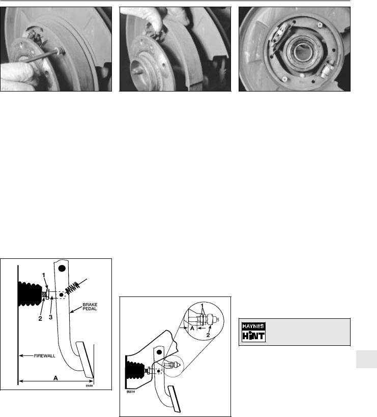
7Remove the shoe return and hold-down springs (see illustrations).
8Remove the shoes (see illustration).
9Refitting is the reverse of removal. When you’re done, the actuator should be properly seated between the two shoes as shown (see illustration).
10After refitting the brake disc, adjust the handbrake shoes. Temporarily refit two wheel bolts, turn the adjuster (see illustration 5.6d) and expand the shoes until the disc locks,
Rear disc brake models
Note: The handbrake system is not selfadjusting on models with rear disc brakes. The handbrake therefore requires periodic adjustment to compensate for wear. It should also be adjusted anytime either cable, brake disc or handbrake assembly is renewed or removed for some reason.
6Slowly apply the handbrake, and count the number of clicks at the lever. If the lever can be pulled up further than the eighth click, adjust the handbrake cable as follows.
7Peel back the handbrake lever boot, and loosen the cable adjusting nut (see illustration 10.1). On some models, it may be necessary to remove the centre console completely for access.
8Loosen a single bolt in each rear wheel.
12.7a Remove the lower shoe return |
12.7b Remove the upper shoe |
spring (diagonal cutting pliers are being |
return spring |
used here because they grip the spring |
|
well, but care must be taken not to cut or |
|
nick the spring) |
|
Braking system 9•13
12.7c Remove the shoe hold-down springs
then back off the adjuster until the shoes don’t drag (see Section 11). Refit the wheel bolts, and tighten them to the torque given in Chapter 1 Specifications.
13 Brake pedal - adjustment |
1 |
|
|
Note: You should always adjust brake pedal height after the master cylinder or brake servo has been removed or renewed. You should also adjust the stop-light switch (see Section 14).
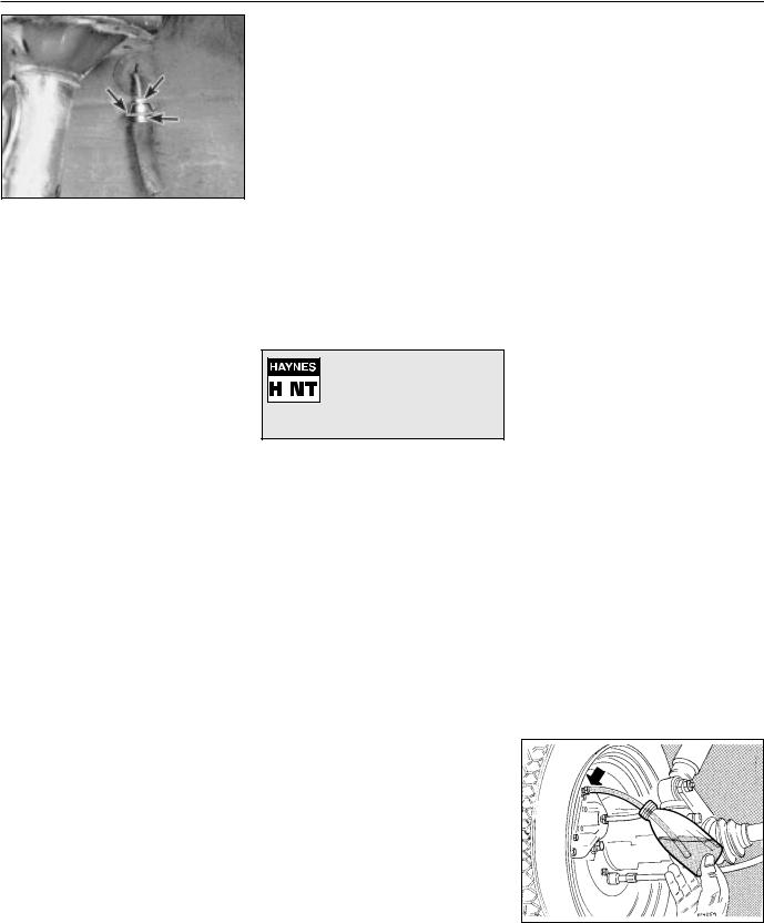
1 Measure the distance between the lower edge of the brake pedal footpad (ie the edge furthest from the bulkhead) and the bulkhead
(see illustration), and compare your measurement with the dimension listed in this Chapter’s Specifications. If it’s not as listed, loosen the locknut on the pushrod, and rotate
13.1 To adjust the brake pedal height, loosen the locknut (1) and turn the pushrod (2) while holding the clevis (3) until dimension A (the distance between the lower edge of the brake pedal and the bulkhead/”firewall”) is within the range listed in this Chapter’s Specifications (left- hand-drive shown, right-hand-drive similar)
12.8 Remove the shoes
the pushrod while holding the clevis stationary until the distance is correct. Note: On right- hand-drive models, the adjustment is carried out at the left-hand side of the cross-shaft, after removing the glovebox, but the dimension is still measured at the pedal.
14 Stop-light switch - |
1 |
check and adjustment |
|
|
|
Note: The stop-light switch should be checked and, if necessary, adjusted after the master cylinder or brake servo has been removed or renewed.
1 The stop-light switch is located on a bracket at the top of the brake pedal. The switch activates the brake lights whenever the pedal is depressed.
2 With the brake pedal in the rest position, measure the distance between the switch contact point on the brake pedal and the switch housing (see illustration) and compare your measurement with dimension A listed in this Chapter’s Specifications.
3 If your measurement is outside the
14.2 To adjust the stop-light switch, loosen the locknuts (1) and screw the switch (2) in or out until dimension A is correct
12.9 When you’re done, the actuator should be properly seated between the two shoes as shown (hub removed for clarity)
indicated dimension, disconnect the wires from the switch. Loosen the locknuts, screw the switch in or out until the plunger dimension is correct, and retighten the locknuts. Reconnect the wires and check for correct operation.
15 Brake hoses and lines - |
4 |
inspection and renewal |
|
|
|
Warning: Brake fluid is poisonous. It is also an effective paint stripper. Refer to the warning at the start of Section 16.
Inspection
1 At the intervals specified in Chapter 1, the brake hoses and lines should be inspected. With the vehicle raised and placed securely on axle stands, the flexible hoses should be checked for cracks, chafing of the outer cover, leaks, blisters and other damage. These are important and vulnerable parts of the brake system, and inspection should be thorough. The metal pipes should be checked for excessive pitting and corrosion. If a hose or pipe exhibits any of the conditions described, renew it.
A torch and mirror will prove |
helpful for a complete hose |
and line check. |
Flexible hose renewal
2 Clean all dirt away from the ends of the 9 hose. Have ready a suitable container to catch spilled brake fluid when the hose is disconnected.
3To disconnect the hose at the chassis end, use a spanner to hold the hex-shaped fitting on the end of the flexible hose, and loosen the nut on the metal brake line (see illustration). If the nut is stuck, soak it with penetrating oil. After the hose is disconnected from the metal line, remove the spring clip from the bracket and detach the hose from the bracket.
4To detach the flexible hose from the caliper,
9•14 Braking system
15.3 A typical brake line-to-brake hose connection: To disconnect it, use one spanner to hold the hex-shaped fitting on the end of the flexible hose (lower right arrow) and loosen the threaded fitting on the metal line with a split ring (“brake”) spanner (upper right arrow), then remove the spring clip (left arrow)
simply unscrew it. Plug the open fitting in the caliper if the hose is removed for any length of time, to prevent dirt ingress.
5 Refitting is the reverse of the removal procedure. Make sure the brackets are in good condition and the locknuts are securely tightened. Renew the spring clips if they don’t fit tightly.
6 Carefully check to make sure the suspension and steering components do not make contact with the hoses. Have an assistant turn the steering wheel from lock-to- lock during inspection.
7 Bleed the brake system as described in Section 16.
Metal brake line renewal
8 When renewing brake lines, use genuine parts only - preferably from a BMW dealer.
9 Genuine BMW brake lines are supplied straight. You’ll need a pipe-bending tool to bend them to the proper shape.
10 First, remove the line you intend to renew, lay it on a clean workbench and measure it carefully. Obtain a new line of the same length, and bend it to match the pattern of the old line.
Warning: Do not crimp or damage the line. No bend should have a smaller radius than
14 mm. Make sure the protective coating on the new line is undamaged at the bends.
11When fitting the new line, make sure it’s well supported by the brackets, that the routing matches the original, and that there’s plenty of clearance between movable components or those components which will become hot.
12After refitting, check the master cylinder fluid level, and add fluid as necessary. Bleed the brake system as outlined in Section 16, and test the brakes carefully before driving the vehicle. Be sure there are no leaks.
16 Brake hydraulic system - |
3 |
bleeding |
|
|
|
Warning: Wear eye protection when bleeding the brake system. If the fluid comes in contact with your eyes, immediately rinse
them with water, and seek medical attention. Most types of brake fluid are highly flammable, and may ignite if spilled onto hot engine components, for example. In this respect, brake fluid should be treated with as much care as if it were petrol. When topping-up or renewing the fluid, always use the recommended type, and ensure that it comes from a freshlyopened sealed container. Never re-use old brake fluid bled from the system, and don’t top-up with fluid which has been standing open for a long time, as it is potentially dangerous to do so.
Brake fluid is an effective
 paint stripper, and will attack
  plastics; if any is spilt, wash it off immediately with copious amounts of water.
Note: Bleeding the hydraulic system is necessary to remove any air which has entered the system during removal and refitting of a hose, line, caliper or master cylinder.
1It will probably be necessary to bleed the system at all four brakes if air has entered the system due to low fluid level, or if the brake lines have been disconnected at the master cylinder.
2If a brake line was disconnected at only one wheel, then only that caliper or wheel cylinder need be bled.
3If a brake line is disconnected at a fitting located between the master cylinder and any of the brakes, that part of the system served by the disconnected line must be bled.
4Bleed the right rear, the left rear, the right front and the left front brake, in that order, when the entire system is involved.
5Remove any residual vacuum from the brake servo by applying the brakes about 30 times with the engine off. This will also relieve any pressure in the anti-lock brake system (where applicable).
6Remove the master cylinder reservoir cover, and fill the reservoir with brake fluid. Refit the cover. Note: Check the fluid level often during the bleeding operation, and add fluid as necessary to prevent the fluid level from falling low enough to allow air into the master cylinder.
7Have an assistant on hand, an empty clear plastic container, and a length of clear plastic or vinyl tubing to fit over the bleed screws. Alternatively, a “one-man” bleeding kit can be used. A “one-man” kit usually contains a tube
or bottle with a one-way valve incorporated - in this way, the pedal can be pumped as normal, but air is not drawn back into the system when the pedal is released. If a oneman kit is used, follow the instructions provided with it; similarly with pressure bleeding kits. In any case, you will also need a supply of new brake fluid of the recommended type, and a spanner for the bleed screw.
8Beginning at the right rear wheel, loosen the bleed screw slightly, then tighten it to a point where it is tight but can still be loosened quickly and easily.
9Place one end of the tubing over the bleed nipple, and submerge the other end in brake fluid in the container (see illustration).
10Have the assistant pump the brakes a few times, then hold the pedal firmly depressed.
Note: If the vehicle is equipped with ABS, have the assistant pump the pedal at least 12 times.
11While the pedal is held depressed, open the bleed screw just enough to allow a flow of fluid to leave the caliper or wheel cylinder. Your assistant should press the brake pedal smoothly to the floor, and hold it there. Watch for air bubbles coming out of the submerged end of the tube. When the fluid flow slows after a couple of seconds, close the screw and have your assistant release the pedal.
12Repeat paragraphs 10 and 11 until no more air is seen leaving the tube, then tighten the bleed screw and proceed to the left rear wheel, the right front wheel and the left front wheel, in that order, and perform the same procedure. Be sure to check the fluid in the master cylinder reservoir frequently.
Warning: Never re-use old brake fluid. It absorbs moisture from the atmosphere, which can allow the fluid to boil and render the brakes inoperative.
13Refill the master cylinder with fluid at the end of the operation.
14Check the operation of the brakes. The pedal should feel solid when depressed, with no sponginess. If necessary, repeat the entire process. Do not operate the vehicle if you are in doubt about the effectiveness of the brake system.
16.9 Place one end of the tubing over the bleed screw, and submerge the other end in brake fluid in the container
10•1
Chapter 10 Suspension and steering systems
Contents
Balljoints - check and renewal . . . . . . . . . . . . . . . . . . . . . . . . . . . . . 7 Control arm (3-Series) - inspection, removal and refitting,
and bush renewal . . . . . . . . . . . . . . . . . . . . . . . . . . . . . . . . . . . . . 3 Control and thrust arms (5-Series) - inspection, removal and
refitting, and bush renewal . . . . . . . . . . . . . . . . . . . . . . . . . . . . . . 4 Front anti-roll bar - removal and refitting . . . . . . . . . . . . . . . . . . . . . 2 Front hub and wheel bearing assembly - removal and refitting . . . . 8 Front strut assembly - removal and refitting . . . . . . . . . . . . . . . . . . . 5 General information . . . . . . . . . . . . . . . . . . . . . . . . . . . . . . . . . . . . . . 1 Power steering fluid level check . . . . . . . . . . . . . . . . See Chapter 1 Power steering pump - removal and refitting . . . . . . . . . . . . . . . . . . 22 Power steering system - bleeding . . . . . . . . . . . . . . . . . . . . . . . . . . . 23 Rack-and-pinion steering gear (3-Series) - removal and refitting . . . 19 Rear anti-roll bar - removal and refitting . . . . . . . . . . . . . . . . . . . . . . 12 Rear coil springs (3-Series) - removal and refitting . . . . . . . . . . . . . . 10 Rear shock absorbers (3-Series) - removal and refitting . . . . . . . . . 9 Rear shock absorber/coil spring assembly (5-Series) - removal
and refitting . . . . . . . . . . . . . . . . . . . . . . . . . . . . . . . . . . . . . . . . . . 11
Rear trailing arms (3-Series) - removal and refitting . . . . . . . . . . . . . 13 Rear trailing arms (5-Series) - removal and refitting . . . . . . . . . . . . . 14 Rear wheel bearings - renewal . . . . . . . . . . . . . . . . . . . . . . . . . . . . . 15 Steering and suspension check . . . . . . . . . . . . . . . . . See Chapter 1 Steering box (5-Series) - removal and refitting . . . . . . . . . . . . . . . . . 21 Steering gear boots (3-Series) - renewal . . . . . . . . . . . . . . . . . . . . . . 18 Steering linkage (5-Series) - inspection, removal and
refitting . . . . . . . . . . . . . . . . . . . . . . . . . . . . . . . . . . . . . . . . . . . . . . 20 Steering system - general information . . . . . . . . . . . . . . . . . . . . . . . 16 Steering wheel - removal and refitting . . . . . . . . . . . . . . . . . . . . . . . 24 Strut or shock absorber/coil spring - renewal . . . . . . . . . . . . . . . . . . 6 Suspension and steering checks . . . . . . . . . . . . . . . . See Chapter 1 Track rod ends - removal and refitting . . . . . . . . . . . . . . . . . . . . . . . 17 Tyre and tyre pressure checks . . . . . . . . . . . . . . . . . See Chapter 1 Tyre rotation . . . . . . . . . . . . . . . . . . . . . . . . . . . . . . . . See Chapter 1 Wheel alignment - general information . . . . . . . . . . . . . . . . . . . . . . . 26 Wheels and tyres - general information . . . . . . . . . . . . . . . . . . . . . . 25
Degrees of difficulty |
|
|
|
|
Easy, suitable for |
Fairly easy, suitable |
Fairly difficult, |
Difficult, suitable for |
Very difficult, |
novice with little |
for beginner with |
suitable for competent |
experienced DIY |
suitable for expert |
experience |
some experience |
DIY mechanic |
mechanic |
DIY or professional |
Specifications |
|
|
|
|
General |
|
|
|
|
Power steering fluid type . . . . |
. . . . . . . . . . . . . . . . . . . . . . . |
. . . . . . . . . See Chapter 1 |
|
|
Tyres |
|
|
|
|
Tyre sizes |
|
|
|
|
3-Series, E30 |
|
|
|
|
316 . . . . . . . . . . . . . . . . . |
. . . . . . . . . . . . . . . . . . . . . . . |
. . . . . . . . . 175/70x14 |
|
|
316i . . . . . . . . . . . . . . . . . |
. . . . . . . . . . . . . . . . . . . . . . . |
. . . . . . . . . 175/70x14, 195/65x14 |
|
|
318i . . . . . . . . . . . . . . . . . |
. . . . . . . . . . . . . . . . . . . . . . . |
. . . . . . . . . 175/70x14 |
|
|
320i . . . . . . . . . . . . . . . . . |
. . . . . . . . . . . . . . . . . . . . . . . |
. . . . . . . . . 195/65x14 |
|
|
325i . . . . . . . . . . . . . . . . . |
. . . . . . . . . . . . . . . . . . . . . . . |
. . . . . . . . . 195/65x14, 200/60x356, 205/55x15 |
|
|
5-Series, E28 (“old-shape”) |
|
|
|
|
518 . . . . . . . . . . . . . . . . . |
. . . . . . . . . . . . . . . . . . . . . . . |
. . . . . . . . . 175x14 |
|
|
518i . . . . . . . . . . . . . . . . . |
. . . . . . . . . . . . . . . . . . . . . . . |
. . . . . . . . . 175x14 |
|
|
|
|
|
|
10 |
525i . . . . . . . . . . . . . . . . . |
. . . . . . . . . . . . . . . . . . . . . . . |
. . . . . . . . . 175x14, 195/70x14 |
|
|
528i . . . . . . . . . . . . . . . . . |
. . . . . . . . . . . . . . . . . . . . . . . |
. . . . . . . . . 195/70x14 |
|
|
535i and M535i . . . . . . . . |
. . . . . . . . . . . . . . . . . . . . . . . |
. . . . . . . . . 220/55x390 |
|
|
5-Series, E34 (“new-shape”) |
|
|
|
|
518i . . . . . . . . . . . . . . . . . |
. . . . . . . . . . . . . . . . . . . . . . . |
. . . . . . . . . 195/65x15 |
|
|
520i . . . . . . . . . . . . . . . . . |
. . . . . . . . . . . . . . . . . . . . . . . |
. . . . . . . . . 195/65x15, 225/60x15 |
|
|
525i . . . . . . . . . . . . . . . . . |
. . . . . . . . . . . . . . . . . . . . . . . |
. . . . . . . . . 195/65x15, 205/65x15, 225/65x15 |
|
|
530i . . . . . . . . . . . . . . . . . |
. . . . . . . . . . . . . . . . . . . . . . . |
. . . . . . . . . 205/65x15, 225/60x15 |
|
|
535i . . . . . . . . . . . . . . . . . |
. . . . . . . . . . . . . . . . . . . . . . . |
. . . . . . . . . 225/60x15, 240/45x415 |
|
|
Tyre pressures . . . . . . . . . . . . |
. . . . . . . . . . . . . . . . . . . . . . . |
. . . . . . . . . See Chapter 1 Specifications |
|
|
10•2 Suspension and steering systems
Torque wrench settings |
Nm |
Front suspension
Strut damper rod nut
Rod with external hexagon . . . . . . . . . . . . . . . . . . . . . . 65 Rod with internal hexagon . . . . . . . . . . . . . . . . . . . . . . 44
Strut cartridge threaded collar . . . . . . . . . . . . . . . . . . . . . . . 130 Strut upper mounting nuts . . . . . . . . . . . . . . . . . . . . . . . . . . 22 Front control arm (3-Series)
Control arm-to-steering knuckle balljoint nut . . . . . . . . . . 64 Control arm-to-subframe balljoint nut . . . . . . . . . . . . . . . 83 Control arm bush bracket bolts . . . . . . . . . . . . . . . . . . . . 41
Lower control arm (5-Series)
Control arm-to-steering arm balljoint stud nut . . . . . . . . . 85 Control arm pivot bolt . . . . . . . . . . . . . . . . . . . . . . . . . . . . 77
Thrust arm (5-Series)
Thrust arm-to-steering arm balljoint stud nut . . . . . . . . . . 85 Thrust arm through-bolt . . . . . . . . . . . . . . . . . . . . . . . . . . 130
Front hub (wheel bearing) nut . . . . . . . . . . . . . . . . . . . . . . . . 290 Steering arm-to-strut bolts (5-Series) . . . . . . . . . . . . . . . . . . 65 Anti-roll bar (3-Series)
Anti-roll bar-to-connecting link bolt . . . . . . . . . . . . . . . . . 41 Anti-roll bar mounting brackets-to-subframe . . . . . . . . . . 22 Connecting link-to-bracket . . . . . . . . . . . . . . . . . . . . . . . . 22 Connecting link bracket-to-control arm . . . . . . . . . . . . . . 41
Anti-roll bar (5-Series)
Anti-roll bar mounting brackets . . . . . . . . . . . . . . . . . . . . 22 Anti-roll bar link-to-strut housing locknut
Yellow chrome . . . . . . . . . . . . . . . . . . . . . . . . . . . . . . . 20 White chrome . . . . . . . . . . . . . . . . . . . . . . . . . . . . . . . . 33 Yellow . . . . . . . . . . . . . . . . . . . . . . . . . . . . . . . . . . . . . . 58
Torque wrench settings |
Nm |
Rear suspension |
|
Rear shock absorber (3-Series) |
|
Shock absorber-to-upper mounting bracket . . . . . . . . . . |
12 to 15 |
Shock absorber-to-trailing arm . . . . . . . . . . . . . . . . . . . . |
71 to 85 |
Rear shock absorber (5-Series) |
|
Lower mounting bolt . . . . . . . . . . . . . . . . . . . . . . . . . . . . . |
125 to 142 |
Upper mounting nut . . . . . . . . . . . . . . . . . . . . . . . . . . . . . |
22 to 24 |
Upper spring mounting-to-shock absorber locknut . . . . . |
22 to 24 |
Trailing arms (3-Series) |
|
Trailing arm-to-lower mounting . . . . . . . . . . . . . . . . . . . . |
71 to 85 |
Trailing arm-to-anti-roll bar . . . . . . . . . . . . . . . . . . . . . . . . |
22 to 23 |
Trailing arms (5-Series) |
|
Trailing arm-to-rear axle carrier (rubber bush |
|
through-bolt and nut) . . . . . . . . . . . . . . . . . . . . . . . . . . |
66 |
Trailing arm-to-axle carrier connecting link (1983-on) . . . |
126 |
Rear wheel bearing drive flange axle nut (5-Series) |
|
M22 . . . . . . . . . . . . . . . . . . . . . . . . . . . . . . . . . . . . . . . . |
175 to 210 |
M27 . . . . . . . . . . . . . . . . . . . . . . . . . . . . . . . . . . . . . . . . |
235 to 260 |
Steering system |
|
Steering wheel retaining nut . . . . . . . . . . . . . . . . . . . . . . . . . |
79 |
Steering column universal joint pinch-bolt . . . . . . . . . . . . . . |
22 |
Steering gear-to-subframe mounting bolts (3-Series) . . . . . |
41 |
Steering box-to-front suspension subframe bolts (5-Series) |
42 |
Track rod end-to-steering arm nut . . . . . . . . . . . . . . . . . . . . |
37 |
Track rod end clamping bolt . . . . . . . . . . . . . . . . . . . . . . . . . |
14 |
Pitman arm-to-steering box (5-Series) . . . . . . . . . . . . . . . . . |
140 |
Steering linkage balljoints (all) . . . . . . . . . . . . . . . . . . . . . . . |
37 |
1 General information
Warning: Whenever any of the suspension or steering fasteners are loosened or removed, they must be inspected and if
necessary, new ones fitted, of the same part number or of original-equipment quality and design. Torque specifications must be followed for proper reassembly and component retention. Never attempt to heat, straighten or weld any suspension or steering component. Any bent or damaged parts must be renewed.
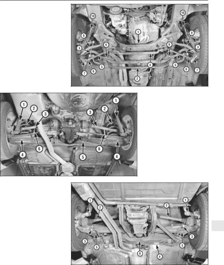
The front suspension (see illustrations) is a MacPherson strut design. The struts are secured at the upper ends to reinforced areas at the top of the wheel arches, and at the lower ends to the steering arms/control arms. An anti-roll bar is attached to the control arms via connecting links, and to the suspension subframe (3-Series models) or the underbody (5-Series models).
The independent rear suspension system on 3-Series models (see illustration) features coil springs and telescopic shock absorbers. The upper ends of the shock absorbers are attached to the body; the lower ends are connected to trailing arms. An anti-roll bar is attached to the trailing arms via links, and to the body with clamps.
The independent rear suspension system on 5-Series models (see illustration) uses coil-
over shock absorber units instead of separate shock absorbers and coil springs. The upper ends are attached to the body; the lower ends are connected to the trailing arms. The rear suspension of 5-Series models is otherwise similar to that of 3-Series models: two trailing arms connected by an anti-roll bar.
The steering system consists of the steering wheel, a steering column, a universal joint shaft, the steering gear, the power
steering pump (where fitted) and the steering linkage, which connects the steering gear to the steering arms. On 3-Series models, a rack-and-pinion steering gear is attached directly to the steering arms via the track rods and track rod ends. On 5-Series models, a recirculating-ball steering box is connected to the steering arms via a Pitman arm, a centre track rod, the outer track rods and the track rod ends.
1.1a Front suspension and steering components (3-Series models)
1 |
Subframe |
3 |
Anti-roll bar link |
5 |
Strut |
7 Steering gear |
2 |
Anti-roll bar |
4 |
Control arm |
6 |
Track rod end |
|
Suspension and steering systems 10•3
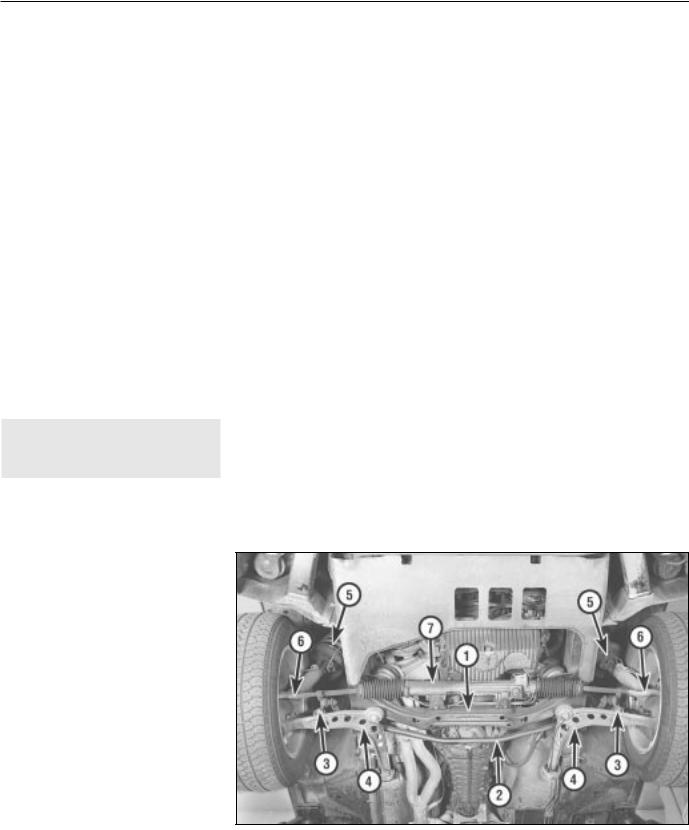
1.1b Front suspension and steering components (5-Series models - left-hand-drive shown)
1Subframe
2Anti-roll bar
3Anti-roll bar link
4Centre track rod
5Outer track rod
6Track rod end
7Steering arm
8Control arm
9Thrust arm
10Strut
1.2 Rear suspension components (3-Series models)
Shock absorber
Coil spring
Driveshaft
Trailing arm
Rear axle carrier
Anti-roll bar link
1.3 Rear suspension components (5-Series models - left-hand-drive shown)
1Shock absorber/coil spring assembly
2Driveshaft
3 Anti-roll bar link |
10 |
4Anti-roll bar
5Trailing arm
6Rear axle carrier
10•4 Suspension and steering systems
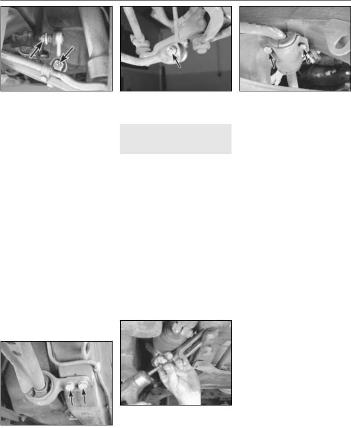
2.2a On 3-Series models, remove the nut (upper arrow) securing the anti-roll bar to the upper end of the connecting link (left side shown, right side similar). If a new control arm is being fitted, remove the lower nut (lower arrow) and disconnect the link assembly and bracket from the arm
2 Front anti-roll bar - |
2 |
removal and refitting |
|
|
|
Removal
1Raise the front of the vehicle, and support it securely on axle stands.
2If you’re removing or renewing the anti-roll bar itself, or disconnecting the bar to renew the strut assembly on a 3-Series model, disconnect it from the anti-roll bar links (see illustrations). If you’re renewing the strut assembly on a 5-Series model, disconnect the anti-roll bar link from the strut housing.
3On 3-Series models, disconnect the left control arm rubber bush from the underbody (see Section 3).
4Remove the bolts from the anti-roll bar brackets which attach the anti-roll bar to the subframe (see illustration).
5Remove the anti-roll bar from the vehicle. Where necessary, separate the anti-roll bar from the strut bar bracket.
Refitting
6 Refitting is the reverse of the removal procedure. Be sure to tighten all nuts and bolts to the torques listed in this Chapter’s Specifications.
3.4 Remove the two bolts (arrowed) securing the bush bracket to the underbody
2.2b On 5-Series models, remove the nut (arrowed) securing the anti-roll bar to the connecting link (left side shown, right side similar)
3 Control arm (3-Series) - |
3 |
inspection, removal and |
|
refitting, and bush renewal |
Inspection
1 Raise the front end of the vehicle, and support it securely on axle stands.
2Grip the top and bottom of each balljoint with a large pair of water pump (“parrot jaw”) pliers, and squeeze to check for free play. Alternatively, insert a lever or large screwdriver between the control arm and the subframe or strut housing. If there’s any free play, renew the control arm (the balljoints can’t be renewed separately).
3Inspect the rubber bush. If it’s cracked, dry, torn or otherwise deteriorated, renew it (see below).
Bush renewal
Note: Rubber bushes should always be renewed in pairs. Make sure both new bushes have the same markings (indicating they’re manufactured by the same firm).
4Remove the two bolts (see illustration) which attach the bush bracket to the underbody.
5Using a puller, remove the bracket and
3.12 Remove the self-locking nut from the balljoint stud protruding through the top of the subframe (not shown in this photo, but it’s directly above the balljoint) and separate the balljoint from the subframe. Try not to damage the dust boot
2.4 Remove the bolts (arrowed) from the anti-roll bar brackets to detach the antiroll bar from the subframe (3-Series model shown, 5-series similar)
bush from the end of the control arm. If the puller slips on the end of the control arm, centre-punch the control arm to give the puller bolt a place to seat.
6Note the orientation of the old bush. This is exactly how the new bush should be orientated when it’s fitted. Press the old rubber bush out of the bracket, or have it pressed out by an engineering works.
7Coat the end of the control arm with BMW’s special lubricant (Part No. 81 22 9 407 284), and press the new bush and bracket onto the arm - or have it pressed on at an engineering works - all the way to the stop.
Caution: Don’t try to use any other type of lubricant;
30 minutes after it’s applied, this lubricant loses its properties and
the bush is permanently located in its proper position. Make sure the new bush is pressed on so it’s orientated exactly the same way as the old bush.
8Refit the bracket bolts and tighten them to the torque listed in this Chapter’s Specifications.
9Lower the vehicle, and leave it at rest for at least 30 minutes (this will give the special lubricant time to dry).
Control arm removal and refitting
Note: If either balljoint is worn or damaged, the only way to renew it is to renew the control arm. If you’re fitting a new control arm, a new bush must also be fitted. The old bush can’t be removed from the old control arm and reused in the new control arm.
10 Loosen but do not remove the wheel bolts, raise the front of the vehicle and support it on axle stands. Remove the wheel bolts and the front wheel.
11Remove the two bolts which attach the rubber bush bracket to the underbody (see illustration 3.4).
12Remove the nut which secures the control arm balljoint to the subframe, and remove the balljoint stud from the subframe. Note: It may be necessary to use a balljoint separator to separate the balljoint from the subframe (see illustration), but take care not to damage the
Suspension and steering systems 10•5
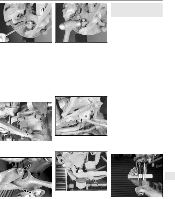
3.13a Remove the self-locking nut from the balljoint stud which attaches the outer end of the control arm to the steering knuckle. If you don’t have a balljoint separator tool . . .
dust boot. If the boot does become damaged (and you’re refitting the same control arm and balljoint), be sure to fit a new boot.
13Unscrew the nut which secures the outer control arm balljoint to the steering knuckle (see illustration) and detach the balljoint stud from the knuckle (see illustration). Ideally you should use a purpose-made balljoint separator tool for this job. Using a hammer is OK if you’re going to fit new parts anyway, but is not recommended if you’re planning to reuse parts.
14Remove the control arm.
4.5 If you’re removing the control arm, remove the three bolts (arrowed) from the steering arm, and separate the strut assembly from the arm
4.6b If you’re removing the thrust arm, remove the nut and bolt (arrowed) that secure the rear end of the arm
3.13b . . . give the steering knuckle a few sharp knocks with a hammer to release the balljoint stud from the strut housing, and remove the control arm
15If you’re renewing the control arm, you’ll have to fit a new bush (see above). The old bush can’t be removed re-used in another control arm.
16Refitting is the reverse of removal. Be sure to use new self-locking nuts on the balljoint studs and tighten them, and the bush bracket bolts, to the torques listed in this Chapter’s Specifications.
17When you’re finished, have the front wheel alignment checked by a dealer service department or qualified garage.
4.6a If you’re removing the control arm, remove the self-locking nut and the through-bolt (arrowed) that attach the inner end of the arm to the vehicle
4 Control and thrust arms |
3 |
(5-Series) - inspection, removal |
|
and refitting and bush renewal |
Inspection
1 Inspect the thrust arm rubber bush (see illustration 4.6b). If the bush is cracked, torn or otherwise deteriorated, renew it. The control arm bush can’t be inspected until the control arm is removed.
2Raise the vehicle and place it securely on axle stands.
3To inspect the control arm and thrust arm balljoints for wear, grip the top and bottom of each balljoint with a large pair of water pump (“parrot jaw”) pliers, and try to squeeze them. Alternatively, use a lever or large screwdriver to move them up and down. If there’s any free play, renew the control arm or thrust arm. The balljoints can’t be renewed separately.
Removal
Note: If a balljoint is worn or damaged, the only way to renew it is to renew the control arm or thrust arm. If you’re fitting a new control arm or thrust arm, a new bush must also be fitted. The old bush can’t be removed from the old control arm or thrust arm and reused in the new arm.
4Loosen the wheel bolts, raise the vehicle and support it securely on axle stands. Remove the wheel.
5If you’re removing the control arm, remove the three bolts from the steering arm (see illustration) and separate the strut assembly from the arm.
6Remove the nut and the through-bolt that secure the control arm or thrust arm rear mounting (see illustrations).
7Remove the nut from the balljoint (see illustration). Support the steering arm and separate the balljoint from the steering arm (see illustrations). Ideally you should use a purpose-made balljoint separator tool for this job. Using a hammer is OK if you’re going to fit new parts anyway, but is not recommended if you’re planning to re-use parts.
10
4.7a Remove the self-locking nut (control |
|
arm nut, left arrow; thrust arm nut, right |
|
|
|
arrow) from the balljoint, then support the |
4.7b You can separate the thrust arm |
steering arm, and press or knock the |
balljoint from the steering arm with a |
balljoint out of the steering arm |
puller . . . |

10•6 Suspension and steering systems
4.7c . . . but you may have to use a hammer to knock the control arm balljoint stud loose from the steering arm, because there’s no room to use a puller. A purposemade balljoint separator tool would be better
Bush inspection and renewal
8 If the bush is cracked, torn or otherwise deteriorated, take the arm to a BMW dealer service department or an engineering works, and have it pressed out and a new bush pressed in. Bushes should always be renewed in pairs (a new bush should be fitted in each arm, and both bushes should have the same manufacturer markings). If you’re fitting a new thrust arm bush, make sure it’s correctly orientated (see illustration).
4.8 Correct orientation of the bush for the
5-Series thrust arm. The arrow on the rubber bush is aligned with the mark on the arm, and the centre of the bush is concentric with the bore
Refit the wheel and tighten the wheel bolts to the torque listed in the Chapter 1 Specifications.
11 Have the front end alignment checked at a dealer service department or qualified garage.
5 Front strut assembly - |
3 |
removal and refitting |
|
|
|
Refitting
9Refitting is the reverse of removal. Be sure to use new self-locking nuts on the balljoint stud nut and the through-bolt. Don’t forget to refit the washers on both sides of the throughbolt. If you’re refitting the control arm, be sure to use thread-locking compound on the steering arm mounting bolts. Don’t tighten the through-bolt to the final torque yet. Note:
Thrust arms are marked “L” for the left side, and “R” for the right side. Be sure to check the marking before fitting a new arm.
10Support the control arm with a trolley jack, and raise it to simulate normal ride height, then tighten the through-bolt to the torque listed in this Chapter’s Specifications.
Removal
Note: Although strut assemblies don’t always fail or wear out simultaneously, renew both left and right struts at the same time, to prevent handling peculiarities or abnormal ride quality.
1Loosen but do not remove the front wheel bolts.
2Raise the front of the vehicle and support it on axle stands.
3Remove the front wheel.
4Detach all brake hoses and electrical wires attached to the strut housing.
5Disconnect the electrical connections for the ABS system, if applicable.
6If you’re removing the left strut, disconnect
the electrical connector for the brake pad wear sensor.
7Remove the bolt securing the ABS wheel sensor, if applicable. Remove the brake disc (see Chapter 9).
8Remove the brake splash shield (see illustration).
9On 3-Series models, disconnect the antiroll bar from its connecting link (see Section 2). On 5-Series models, disconnect the anti-roll bar link from the strut housing (see Section 2).
10On 3-Series models, disconnect the control arm balljoint from the steering knuckle (see Section 3) and the track rod end from the steering arm (see Section 17).
11On 5-Series models, disconnect the bolts that attach the steering arm to the strut housing (see illustration 4.5).
12Pull out the lower end of the strut housing far enough to clear the end of the control arm (3-Series) or the steering arm (5-Series).
13Support the weight of the strut and remove the three mounting nuts at the top of the strut, located inside the engine compartment (see illustration) and remove the strut.
14Remove the strut assembly. If a new shock absorber (strut cartridge) is being fitted, see Section 6.
Refitting
15Refitting is the reverse of removal. On 3-Series models, be sure to use new selflocking nuts on the control arm balljoint, the track rod end balljoint and the strut upper mountings. On 5-Series models, make sure the tang in the steering arm is mated with the notch in the strut housing (see illustration). BMW recommends using a thread-locking compound on the steering arm mounting bolts. On all models, tighten the fasteners to the torques listed in this Chapter’s Specifications.
16When you’re done, drive the vehicle to a dealer service department or qualified garage and have the wheel alignment checked, and if necessary, adjusted.
5.8 To remove the brake splash shield, |
5.13 Support the weight of the strut and |
5.15 On 5-Series models, make sure the |
remove these three bolts (arrowed) |
remove the three mounting nuts (arrowed) |
tang in the steering arm is mated with the |
|
at the top of the strut (5-Series shown, |
notch in the strut housing (arrowed) |
|
3-Series similar) |
|
Suspension and steering systems 10•7
6 Strut or shock absorber/coil |
4 |
spring - renewal |
|
|
|
Note: This section applies to all front strut assemblies and, on 5-Series models, the rear coil-over shock absorber assemblies.
1 If the struts, shock absorbers or coil springs exhibit the telltale signs of wear (leaking fluid, loss of damping capability, chipped, sagging or cracked coil springs) explore all options before beginning any work. Strut or shock absorber assemblies complete with springs may be available on an exchange basis, which eliminates much time and work. Whichever route you choose to take, check on the cost and availability of parts before dismantling the vehicle.
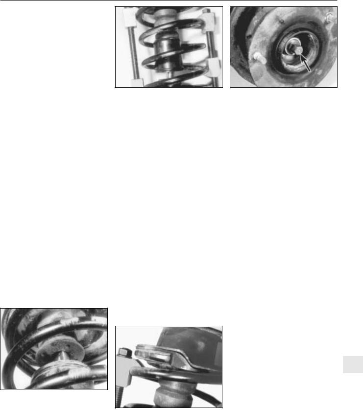
6.3 Following the tool manufacturer’s instructions, fit the spring compressor to the spring, and compress it sufficiently to relieve all pressure from the suspension support
damper rod nut, and remove the large nut (arrowed) - to prevent the damper rod from turning, place an Allen key in the end of the shaft
Warning: Dismantling a strut or coil-over shock absorber assembly is a potentially dangerous undertaking, and
utmost attention must be directed to the job, or serious injury may result. Use only a high-quality spring compressor, and carefully follow the manufacturer’s instructions supplied with the tool. After removing the coil spring from the strut assembly, set it aside in a safe, isolated area.
2 Remove the strut or shock absorber assembly (see Section 5 or 11). Mount the assembly in a vice. Line the vice jaws with wood or rags to prevent damage to the unit, and don’t tighten the vice excessively.
3 Following the tool manufacturer’s instructions, fit the spring compressor (these can be obtained at most car accessory shops, or it may be possible to hire one) on the spring, and compress it sufficiently to relieve all pressure from the suspension support (see illustration). This can be verified by wiggling the spring.
4 Prise the protective cap off the damper rod self-locking nut. Loosen the nut (see illustration) with a spanner while holding the
6.9 Loosen and remove the threaded collar, and pull the old strut cartridge from the strut housing - on all struts except gas-charged units, pour the old oil from the strut housing. (Spring should have been removed first!)
damper rod stationary with another spanner or an Allen key.
5 Remove the nut, the strut bearing, the insulator and the large washer. Check the bearing for smooth operation. If it doesn’t turn smoothly, renew it. Check the rubber insulator for cracking and general deterioration. If there is any separation of the rubber, renew the insulator.
6Lift off the spring retainer and the rubber ring at the top of the spring. Check the rubber ring for cracking and hardness. Renew it if necessary.
7Carefully lift the compressed spring from the assembly and set it in a safe place, such as a steel cabinet.
Warning: Never place your head near the end of the spring!
8 Slide the protective tube and rubber bumper off the damper rod. If either is damaged or worn, renew it.
9 If you’re working on a front strut, loosen and remove the threaded collar (see illustration) and pull the old strut cartridge from the strut housing. Pour the old oil from the strut housing.
10 On all struts except gas-charged units, fill the strut housing with 20 to 25 cc (3-Series), 42 to 47 cc (518i and 520i 5-Series models) or 20 to 25 cc (all other 5-Series models) of
6.11 Make sure you align the end of the coil spring with the shoulder of the rubber ring, and with the spring retainer
engine oil (the oil helps cool the shock |
|
||
absorber by transferring heat to the strut |
|
||
housing). Note: It doesn’t matter |
what |
|
|
viscosity or grade of engine oil is used. |
|
|
|
11 Refitting is otherwise the reverse of |
|
||
removal. Tighten the threaded collar to the |
|
||
torque listed in this Chapter’s Specifications. |
|
||
Make sure you align the end of the coil spring |
|
||
with the shoulder of the rubber ring and with |
|
||
the spring retainer (see illustration). Tighten |
|
||
the damper rod nut to the torque listed in this |
|
||
Chapter’s Specifications. |
|
|
|
12 Refit the strut or shock absorber |
|
||
assembly (see Section 5 or 11). |
|
|
|
|
|
|
|
7 Balljoints - check and renewal |
3 |
|
|
|
|
|
|
Check |
|
|
|
Note: On 3-Series models, there are two |
|
||
balljoints on each control arm - one between |
|
||
the middle of the arm and the subframe, and |
|
||
the other between the outer end of the arm |
|
||
and the steering knuckle. On 5-Series models, |
|
||
there are balljoints on the outer ends of the |
|
||
control arm and the thrust arm. |
|
|
|
1 Raise the vehicle and support it securely on |
|
||
axle stands. |
|
|
|
2 Visually inspect the rubber boot between |
|
||
the balljoint and the subframe or steering |
|
||
knuckle, etc for cuts, tears or leaking grease. |
|
||
If you note any of these conditions, renew the |
|
||
control arm or thrust arm - the balljoints are |
|
||
not available separately. |
|
|
|
3 Place a large lever under the balljoint, and |
|
||
try to push the balljoint up. Next, position the |
10 |
||
lever between the arm and the subframe or |
|||
between the arm and steering knuckle. If you can see or feel any movement during either check, a worn balljoint is indicated.
4 Have an assistant grasp the tyre at the top and bottom, and shake the top of the tyre with an in-and-out motion. Touch the balljoint stud nut. If any looseness is felt, suspect a worn balljoint stud or a widened hole in the subframe or steering knuckle. If the latter