

A Savelyev DYNAMIC POSITIONING SYSTEM
.pdf
 Dynamic Positioning System Chapter 2 ELEMENTS OF A DYNAMIC POSITION SYSTEM
NOTE: To allow redundancy and other control options, such as minimum power consumption, position control, and barred zones for azimuthing thrusters, vessels must have more than the minimum thruster configuration.
Thrusters are usually positioned to provide a maximum moment, minimum interference with other thrusters and sensors, and below the water line.
Other possible thrusters are:
Pump Jet Thruster - centrifugal pump impeller, mounted on a vertical axis, with the suction intake flush on the hull bottom. The volute pump casing ejects the water and generates thrust in the horizontal direction. The whole unit can rotate 360° providing the function of an azimuth thrusters. The pump drive can be electric motor or diesel and is used in shallow water operations. Pump jets may be used as main propulsion or thrusters for maneuvering purposes.
Gill Jet Thruster – motor-driven impeller pumps water through a tunnel into a bottommounted discharge deflector. This deflector can rotate 360°. Because the vertical discharge velocity of water is deflected to the horizontal, it generates thrust. Can be used as a full azimuth thrusters and may be considered as an emergency propulsion mode.
Water Jet – jet unit is mounted inboard in the aft section with water entering the jet unit intake on the bottom of the vessel, at vessel speed, and is accelerated through the jet unit and discharged through the transom at a high velocity. Steering is achieved by changing the direction of the stream of water as it leaves the jet unit. Pointing the jet stream one way forces the stern of the vessel in the opposite direction which puts the vessel into a turn. Reverse is achieved by lowering an astern deflector into the jetstream after it leaves the nozzle. This reverses the direction of the force generated by the jet stream, forward and down, to keep the vessel stationary or propel it in the astern direction.
CONROL ELEMENTS
DYNAMIC POSITIONING OPERATOR (DPO)
Sets the position, heading, and mode of operation and any number of functions required of the DP system.
Enters the limits or deviations required for a set position, heading, or other applicable items. Mans and monitors the DP console.
DYNAMIC POSITIONING CONSOLE
The interface containing the computer display, indicators, buttons, switches, track ball, joystick, alarms, etc used by the DPO to monitor the DP systems and input required commands for maintaining heading and position.
Generally located near thruster panels, communication systems, position measurement equipment, control panels, and more.
DYNAMIC POSITIONING COMPUTERS
Located in the consol.
Analize inputs from the DPO, position measurement equipment sensors, power generation, main propulsion, and thrusters systems. And process the commands to applicable systems to maintain the vessel’s heading, position, or track.
Programmable logic controller (PLC) is considered the core of the control elements.
- 5 -

 Dynamic Positioning System Chapter 2 ELEMENTS OF A DYNAMIC POSITION SYSTEM
Programmed sololy for DP processing (the operating system and programming are usually restricted to prevent unauthorized modifications, of the DP program) .
Installed in single, dual, or triple configurations, depending on the level of redundancy required.
A single computer (simplex system) offers no redundancy.
Two-computer configuration (duplex system) offers redundancy by automatically switching to the back up computer if the online system fails.
A free-computer configuration (triplex system) offers additional redundancy and security.
- 6 -


 Dynamic Positioning System Chapter 2 ELEMENTS OF A DYNAMIC POSITION SYSTEM
POWER AND FORCE GENERATION
A DP vessel is potentially vulnerable to power shortages, blackout, or partial blackout conditions, which might put the DP system at risk.
Power generation is the “heart” of the DP system.
DP computers, console, position measurement equipment, sensors, and thrusters need power to operate.
The power generation system must be capable of meeting high power demands by the control system, while “scaling” back when power demand is low, in order to conserve fuel. The control system has an Uninterrupted Power Supply (UPS) to provide a temporary backup power to the DP controls, computers, displays and reference systems. UPS ensures additional safety for continuing DP operations.
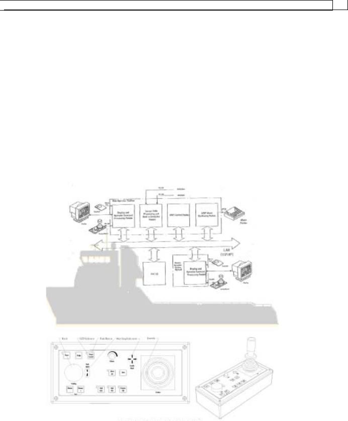
A typical power supply installation on an Offshore Supply Vessel (OVS).
The control system has uninterrupted power supply (UPS) to provide a temporary backup power to the DP controls, computers, displays, and reference systems.
- 7 -


 Dynamic Positioning System Chapter 2 ELEMENTS OF A DYNAMIC POSITION SYSTEM
POSITION MEASUREMENT EQUIPMENT(PME)
Five Types of Position Measurement Equipment generally used on DP vessels:
Different Global Positioning System.
Hydroacustic Position Reference.
Taut Wire.
Laser-based System.
Artemis.
SENSORS
HEADIUNG REFERENCE
Gyro compass:
Provides heading data to the DP system.
DP vessels that require redundancy have two or more giro compasses.
If only two girocompasses are installed, the DP system is limited to monitoring the difference in heading data. And, issuing a warning if the difference axceeds a certain value.
- 8 -


 Dynamic Positioning System Chapter 2 ELEMENTS OF A DYNAMIC POSITION SYSTEM
If free girocompasses fitted, the DP system can use two-out-of-three voting to determine a giro failure, and give a warning accordingly.
The giro compass has a direct feed into the DP system.
Magnetic Compass:
Provides heading and bearing information relative to magnetic north.
Used as an external backup reference.
Does not feed information to the DP System.
ENVIRONMENT REFERENCE
In DP operations, environmental forces affecting the vessel’s and heading are dividedinto two groups:
Wind – movement of air from high pressure area to a low pressure area.
Current - consists of the horizontal movement of water (tide), waves, swells, and any other
force.
WIND SENNSORS
Sensors are used to monitor
the effects of wind and urent on the vessel. The data from sensors are fed
into the DP computer for analysis. The
appropriate command or compensation is issued to applicable DP systems.
The anemometer (shown in pictures above and speed of the wind.
ERTICAL REFERENCE
The VRU is a sensor used to measure the vessel roll and
pitch.
The Motion Reference Unit (MRU), like the VRU
Measures roll and pitch. In addition, the MRU also measures
heave.
MOTION REFERENCE
Giro compass is used to provide heading and bearing information relative to tue north.
Magnetic compass gives heading and bearing information relative to tue north.
- 9 -


 Dynamic Positioning System Chapter 2 ELEMENTS OF A DYNAMIC POSITION SYSTEM
REDUNDANCY IN DP SYSTEM
Redundancy, according to the International Maritime Organization (IMO), is the “ability ofcomponent or system to maintain or restore its function, when a single failure has occurred.”
The essence of redundancy is to enable the vessel to safely terminate a DP operation after losing a critical component or system. This concept is referred to as “Single Point Failure” mode. Most DP vessels have propulsion/thruster configurations beyond the minimum, as these provide control options such as minimum power consumption, fine position control, and barred zones for azimuthing thrusters to protect equipment. It also allows redundancy, which is the ability of a vessel to maintain position and heading despite losing a component within its DP system. Redundancy gives a DP vessel added time to safely shut down an operation should an failure occur n the DP system. Potential hazard associated with a DP operation is key in determining the level of redundancy. As a general rule, the greater the risk to life and property, the higher the level of redundancy required.
DP vessel are required to have all failure modes and their effects considered in a formal FMEA (Failure Modes and Effects Analysis) study. The results of the FMEA study are generally required by pre-charter auditors, inspections, and the classification society.
CONSEQUENCE ANALYSIS
IMO DP Class 2 and 3 vessels guidelines require a system of Online Consequence Analysis to be incorporated in the DP system. This system consistently analysis the vessel’s ability to maintain position and heading after a predefined, worst case failure during DP operation. Possible consequences are derived from actual weather conditions, active thrusters and power generation status. A single worst-case failures could be:
Failure in the most critical thruster. Failure in a thruster group.
Failure in a power bus section.
If a loss of position results from the predefined failure, an alarm is generated for this possibility.
DP CAPABILITY ANALYSIS SYSTEM
This teature in some modern DP systems, predicts the maximum weather conditions that the vessel is able to continue DP operations (maintain position and heading within specified limits, taking into account both the average environmental load and the vessel dynamics). The weather conditions are defined by a one minute mean maximum wind velocity, a most-probable significant wave height, and a most-probable wave modal period.
Situations evaluated:
All systems fully operational; all thrusters active and no lack of power.
Present condition with regard to thrusters and generators.
Loss of one or more thruster units.
Loss of one or more power generators (with possible loss of connected thrusters).
The results of the analysis are displayed graphically as wind holding-capability plots. These plots or rosettes show the limiting one-minute mean wind velocity for all vessel headings. By monitoring this display, the DPO can view the present operational margins with respect to the environmental
- 10 -


 Dynamic Positioning System Chapter 2 ELEMENTS OF A DYNAMIC POSITION SYSTEM
conditions, and the optimum heading to select for safe operation. The limiting weather conditions for the different situations are also displayed as numeric information. Using an electronic beating line the DPO can read out the limiting figures for any vessel heading. The analysis can be updated every five minutes, taking into account the most recent changes in the environmental conditions.
DP VESSEL CLASSES
A system control and redundancy determines a vessel’s DP class. Classes with complete
redunancy will not lose heading or position from a single fault failure. |
|
DP CLASS 0 |
DP CLASS 1 |
Automatic heading control. |
Automatic heading control. |
Manual position control. |
Automatic position control. |
|
Non complete redundancy. |
DP CLASS 2 |
|
DP CLASS 3 |
|
Automatic heading |
control. |
Automatic heading |
control. |
Automatic position |
control. |
Automatic position |
control. |
Complete redundancy including |
Triple redundancy including |
||
thrusters and power. |
|
thrusters and power, fire and flooding. |
|
IMO |
NMD |
|
Lloyds |
ABS |
BV |
Equipment |
Consiquence |
DNV Class Notation |
Class |
Class |
Class |
Class |
Class |
|
Notation |
Notation |
Notation |
|
|
|
|
|
|
|
Class 0 |
DNV/T |
DP(CM) |
DPS-0 |
DYNAPOS |
|
|
|
|
|
SAM |
|
|
|
|
|
|
Class 1 |
Class 1 |
NV-AUTS |
DP(AM) |
DP-1 |
DYNAPOS |
|
|
|
|
|
AM/AT |
Class 2 |
Class 2 |
DNV-AUTR |
DP(AA) |
DP-2 |
DYNAPOS |
|
|
|
|
|
AM/AT R |
|
|
|
|
|
|
Class 3 |
Class 3 |
DNV-AUTRO |
DP(AAA) |
DP-3 |
DYNAPOS |
|
|
|
|
|
AM/AT RS |
|
|
|
|
|
|
- 11 -


 Dynamic Positioning System Chapter 2 ELEMENTS OF A DYNAMIC POSITION SYSTEM
MATHEMATICAL MODELING IN DP SYSTEM
Wind, waves, current, fire monitors, cable or pipelay tension are some of the forces that cause a DP vessel to wander off location.
The giro compass, position measuring equipments, wind sensor, vertical reference unit, or motion reference sensor, measure the vessel’s reaction to “offsetting” forces.
The Mathematical Model is designed to compute the difference between the “setpoint” values and “offset” values of heading and position. And, to issue thrusters command to counteract offsetting force(s) to return the vessel to the “setpoint” heading and position.
A Kalman Filter is used to enhance the mathematical modeling process.
The Mathematical Model is a special calculating module (hydroand aerodynamic vessel description) that continually calculates the vessel’s response from external distarbences, as well as from on board actuators (thrusters, etc). The response is indirectly estimated fromsensor data.
Wind speed and wind angle, relatively to a vessel, are parameters of wind disturbance. forces and moment are calculated based on aerodynamic vessel hull characteristics. Data from follow up
- 12 -


 Dynamic Positioning System Chapter 2 ELEMENTS OF A DYNAMIC POSITION SYSTEM
control system sensors are parameters, instantaneous forces from propellers, rudders and thruster are calculated.
All vessel particulars: mass, draft, dimensions, hull type, propulsion unit type, thrusters types and structure and superstructure location, ect. are taken into account in the Mathematical Model, which is modified in accordance with sea trial data and then applicable to the actual vessel.
The Mathematical Model adjustment is as accurate as possible and describes all possible modes of vessel motion from axternal disturbances as well as on board actuators.
Advantages:
Multiple position measuring equipments (PNEs) are integrated in the mathematical model to refine position determination.
Utilizes data from sensors and other sources in the modelling process. Rudder is not required for rotation control.
Capable of recognizing and abandoning “questionable” data.
Can maintain the vessel headin and position, on a deteriorating basis, after losing input from PMEs and/or various sensors.
Limitations:
Initial design may be based on conditions that may not fully represent present operating conditions of the vessel.
The mathematical model generally does not have provision to directly measure tide and current.
KALMAN FILTER
Vessel motion control algorithms use vessel motion parameters: fore-aft (X axis) and athwartship forces (Y axis), yaw rate (N axis), heading, and coordinates. Also, it is necessary to know the parameters of current: speed and angle relatively to a vessel.
However, not all parameters can be measured quite accurately and some of them cannot be measured at all, therefore it is necessary to estimate these parameters. Parameters are connected to each other via vessel motion equations and the Mathematical Model allows their estimation. Vessel motion parameters also depend on axternal disturbances (wave), which cannot be measured. Wave disturbance is taken into account by wave filters.
The Mathematical Model is not perfect. For this reason, measured data and data received from the Mathematical Model are used together and are processed by the Kalman Filter algorithm. The Kalman Filter uses a vessel motion mathematical model for predicting measurements. Vessel position data comes from several sensors (with different characteristics). Measurements, processed by filter, are weighed in accordance with their noise levels and then used for updating of vessel state, received from the Mathematical Model.
The Kalman Filter algorithm allows generation of an optimal estimation of vessel motion parameters and parameters of current. Also, if measurements are absent, such algorithms allow a comparatively accurate prediction if vessel motion parameters for some period of time.
Advantages of using a Vessel Model and Kalman Filter:
Filtered sensor signals reduce noise and thrusters activity.
- 13 -


 Dynamic Positioning System Chapter 2 ELEMENTS OF A DYNAMIC POSITION SYSTEM
Erroneous data is compared with model data and rejected.
Data of different position measurement equipment combined while matching thecharacteristics of the individual reference system.
Mode Control or Dead Reckoning (DR) - vessels, with the loss of position or heading inputs, can remain under automatic control by using estimated data that is based on the
conditions of the previous few minutes.
Vessels have an extended operational window since positioning can be maintained during more weather conditions.
WAVE FILTER
The Wave Filter is extension of the Kalman Filter. Wave Filters are intended for highfrequency wave disturbance filtering and low frequency vessel motion extraction. The Wave Filter takes into account high frequency vessel motion under wave disturbance. Threesecond order filters are used.
For description of wave disturbance along the longitudinal axis.
For description of wave disturbance along the transversal axis.
For description of disturbing moment relative to the vertical axis.
- 14 -