

Motion_Sim_Instructor_WB_2011_SV[1]
.pdfBasic Functionality of SolidWorks Motion
Motion analysis type
SolidWorks offers three types of the assembly motion simulation:
1Animation is simple motion simulation ignoring the components’ inertial properties, contacts, forces and similar. Its use is suited for the verification of the correct mates or basic animations, for example.
2Basic Motion offers some level of realism by accounting for the inertial properties of the components for example. It does not, however, recognize externally applied forces.
3Motion Analysis is the most sophisticated motion analysis tool reflecting all required analysis features such as inertial properties, external forces, contacts, mate friction etc.
Under Type of Study on the left hand side of the SolidWorksMotionManager,
select Motion Analysis.
Simulation time
The duration of the motion simulation is driven by the topmost time line in the SolidWorksMotionManager. Because SolidWorks Motion sets the default analysis duration to 5 seconds this parameter needs to be modified.
Move the end time key of the topmost timeline from 5 second to a 1 second location.
Note: The zoom keys  allow you to zoom in and out on the time line.
Right-clicking on the timeline key allows you to manually input the desired simulation time.
Running the Simulation
In the SolidWorksMotionManager click the Calculate icon  .
.
Note the motion simulation during the calculation.
Looking at the Results
Absolute results in the global coordinate system
First let us plot the angluar velocity and acceleration for Link1.
Click the Results and Plots icon  to open the Results dialog.
SolidWorks Motion Instructor Guide |
2-14 |

Basic Functionality of SolidWorks Motion
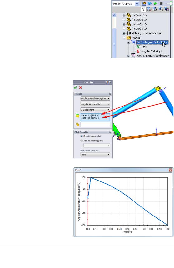
Under Results select Displacement/Velocity/ Acceleration, Angular Velocity and Z Component.
Still under Results select Link1.
The Component to define XYZ directions (optional) field is used to reference our plot results with respect to a local coordinate system of another moving component. To plot the results in the default coordinate system shown in the figure, leave this field empty.
Click OK to show the plot.
The plot shows the variation of the angular velocity of the center of mass for Link1 as function of time.
Repeate the above procedure to plot
the Z Component of the Angular Acceleration for the center of mass of Link1.
In the global coordinate system, the results indicate the maximum angular velocity and angular acceleration of 6 deg/sec and 38 deg/sec^2, respectively.
Similarly, create the plots of the Z Component of angular velocity and angular acceleration at the center of mass for Link2 and Link3.
SolidWorks Motion Instructor Guide |
2-15 |
Basic Functionality of SolidWorks Motion
Storing and editting result plots
The generated result plot featuers are stored in the newly created Results folder on the bottom of the SolidWorksMotionManager.
Right-clicking on any plot feature allows you to hide and show the plot, as well as edit its settings.
More on the Results
Relative results in global coordinate system
Let us plot the Z Component of the relative angular acceleration of Link1 with respect to Link3.
Expand the Results folder. Make sure that Plot2 is shown. Rightclick on Plot2 and select Edit
Feature.
Select Link3 as the second
component in the Select one or two part faces or one mate/simulation element to create results field.
Click OK to show the plot.
The plot shows the acceleration magnitude of Link1 (its center of mass) with respect to Link3 (part’s coordinate system). The maximum relative acceleration is 139 deg/sec^2 in the negative rotational Z direction.
Note also that the variation of the acceleration chagned significantly when compared to the absolute acceleration result for Link1 alone above.
Note: The positive rotational direction can be determined using the right hand rule. Point the thumb of the right hand into the direction of the axis (in our case it would be the Z axis). Your fingers will then show the positive direction for the Z component of the rotation.
SolidWorks Motion Instructor Guide |
2-16 |

Basic Functionality of SolidWorks Motion
Relative results in local coordinate system
Let us transform the Z component of the absolute acceleration of Link1 into the local coordinate system of Link2.
Edit the above plot, Plot2, delete Link3 from the Select
one or two part faces or one mate/simulation element to create results field.
Then select Link2 in the
Component to define XYZ
directions field. Click OK to show the plot.
Note: The triad on the Link2 component indicates the output local coordinate system. Contrary to the global coordinate system which is fixed, local coordinate systems may rotate. In our case, the selected local coordinate system will rotate because Link2 component rotates as the mechanism moves.
The maximum Z component of absolute acceleration of Link1 in the local coordinate system of Link2 is 38 deg/sec^2 in the negative Z rotational direction.
Comparing this absolute result in the local corodinate system to the absolute acceleration in the global coordinate system, we conclude that they are identical. This is because Z axes in both systems are aligned.
Repeate the above for various selection of components and local coordinate systems.
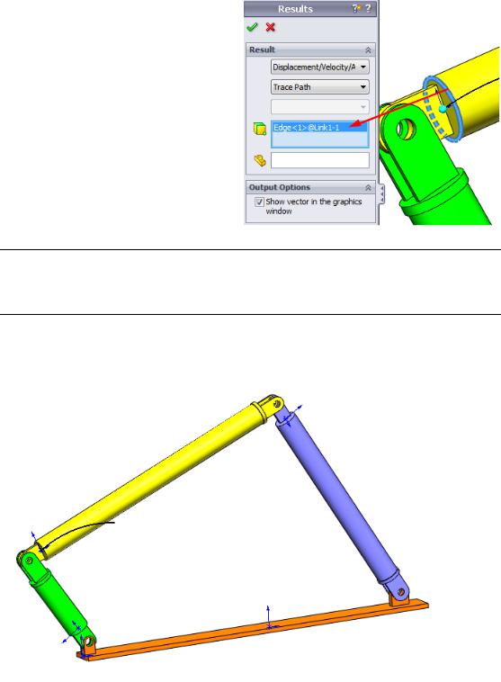
Create a Trace Path
SolidWorks Motion allows you to graphically display the path that any point on any moving part follows. This is called a trace path. You can create trace path with reference to any fixed part or with reference to any moving component in the assembly. We will create a trace path for a point located on Link1 component.
To create a trace path right click on the Results and Plots icon.
SolidWorks Motion Instructor Guide |
2-17 |
Basic Functionality of SolidWorks Motion
In the Results dialog select Displacement/ Velocity/Acceleration and Trace Path.
In the first selection field select the circular edge on Link1 to identify the center point of the circle. The sphere graphically shows the center of the circle.
Check the Show vector in graphics window check box.
The path will then show on the screen as black curve.
Note: The resulting trace path is by default shown with respect to the fixed ground. To show the trace path with respect to another moving component, one would have to select this reference component as a second item in the same selection field.
Click OK to close the Results dialog.
Zoom out to see the entire model and Play the simulation.
This completes your first SolidWorks Motion simulation.
SolidWorks Motion Instructor Guide |
2-18 |

Basic Functionality of SolidWorks Motion
5 Minute Assessment – Answer Key
1. How do you start a SolidWorks Motion session?
Answer: On the Windows task bar, click Start, Programs, SolidWorks, SolidWorks Application. The SolidWorks application starts. Click the SolidWorks Motion Manager tab (by default named Animation1) on the bottom of the SolidWorks document window.
2. How do you activate SolidWorks Motion Add-In?
Answer: Click Tools, Add-Ins, check SolidWorks Motion to select it, and click OK. 3. What types of motion simulations are available in SolidWorks?
Answer: SolidWorks features three types of the motions simulations: Animation, Basic Motion, Motion Analysis.
4. What is analysis?
Answer: Analysis is a process to simulate how your design performs in the field. 5. Why analysis is important?
Answer: Analysis can help you design better, safer, and cheaper products. It saves you time and money by reducing traditional, expensive design cycles.
6. What does SolidWorks Motion analysis calculate?
Answer: Motion analysis calculates displacements, velocities, accelerations and reaction forces on your model when it moves.
7. Does SolidWorks Motion assume the parts to be rigid or flexible?
Answer: SolidWorks Motion does only rigid body analysis and hence assumes all parts to be perfectly rigid.
8. Why is motion analysis important?
Answer: Motion analysis can tell you how safe and economical your design is under its operating conditions.
9. What are the main steps in performing motion analysis?
Answer: The main steps are: creating the mechanism in SolidWorks (creating the mates), applying motion to the driving part, running the simulation and visualizing the results.
10. What is a trace path?
Answer: A trace path is a path or trajectory that any point on a moving part follows. 11. Are SolidWorks mates used in SolidWorks Motion model?
Answer: Yes. SolidWorks mates are used to automaticaly created internal joints in SolidWorks Motion. Mates therefore define the motion of the simulated mechanism.
SolidWorks Motion Instructor Guide |
2-19 |
Basic Functionality of SolidWorks Motion
In Class Discussion – Calculating the Torque needed to drive the 4 bar mechanism
Ask the student how the angular motion was given to the driving link of the 4Bar mechanism. Often times such mechanisms are driven by motors. One important parameter in sizing the motor is the torque generated by the motor, which is one of the standard output quantities in SolidWorks Motion. Finding this torque will help us choose the right motor for the application.
How is the torque calculated from SolidWorks Motion?
Answer
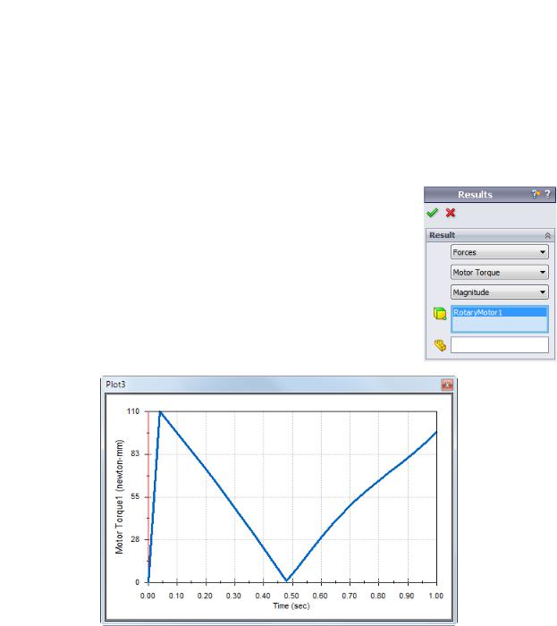
Click on the Results and Plots icon to open the Results dialog.
Specify Forces, Motor Torque, Magnitude and select the
RotaryMotor1 feature driving the mechanism (in this example we gave the Link2 an angular velocity of 45 degrees in 1 sec).
Click OK to generate the plot.
The required torque is about 110 N-mm
SolidWorks Motion Instructor Guide |
2-20 |
Basic Functionality of SolidWorks Motion
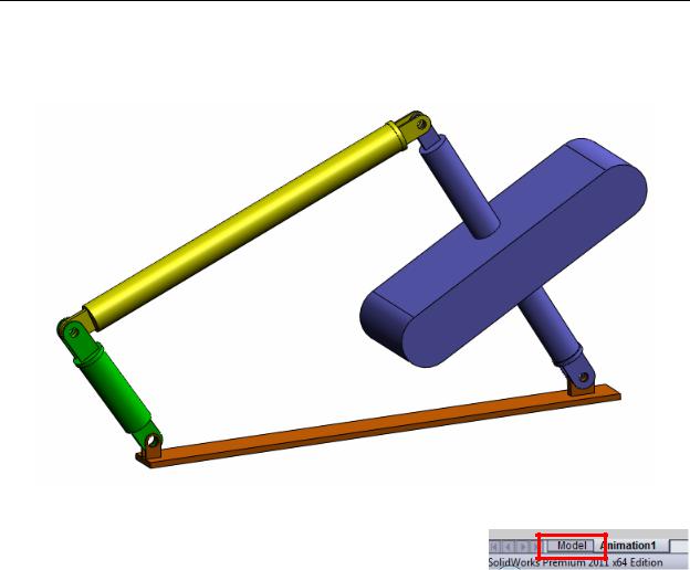
More to Explore — Modifying the Geometry
Ask the students to modify the geometry of Link3 so that the 4Bar mechanism looks like the one shown in the image below. Now ask them to use SolidWorks Motion to calculate the new torque required to drive this mechanism. Use the same uniform angular velocity input of 45 deg/sec. Will the new driving torque be higher or lower? Why?
Answer
1Click the Model tab on the bottom of the SolidWorks document window.
2Open the part Link3.
3Unsuppress the feature Extrude5 from the SolidWorks feature tree.
4Save the part Link3 and close the part.
5When you come to the assembly 4Bar you will see the new and updated assembly. (Note that when prompted to update your assembly, select Yes)
6Now go to SolidWorks Motion (in our case click the Animation1 tab on the bottom of the SolidWorks document folder). Notice that all the mates are retained. Also make sure that the Link2 angular motion is the same.
7Click the Calculate icon.
8Plot the torque and determine the new required magnitude.
The required driving torque is now higher because Link3 is heavier; it takes more torque to drive the mechanism.
SolidWorks Motion Instructor Guide |
2-21 |

Basic Functionality of SolidWorks Motion
Exercises and Projects — Slider Crank Mechanism
Now you will see how to use SolidWorks Motion to simulate a slider crank mechanism. The goal is to calculate the velocity and acceleration of the center of mass of the reciprocating part.
Tasks
1Open the SliderCrank.sldasm located in the corresponding subfolder of the
SolidWorks Curriculum_and_Courseware_2011 folder and click Open
(or double-click the part).
This model represents a slider crank mechanism where a rotary motion of the crank is transformed into reciprocating translational motion of the slider. The crank is rotated with a uniform velocity of 360 degrees per second.
2Review the fixed and moving parts in the assembly.
Answer: Parts fixed in SolidWorks are also treated as fixed in SolidWorks Motion. In our case the Ground and BasePart are fixed, the remaining components are moving.
3Prescribe uniform 360 deg/sec rotational velocity to the Crank. Make sure that the motion is specified at the BasePart/Crank pin location. (You can enter 360 deg/sec directly into the Motor speed field. SolidWorks Motion then converts the value to RPM).
Answer: Do the following.
• Right-click on the Motor icon to open the Motor dialog.
SolidWorks Motion Instructor Guide |
2-22 |

Basic Functionality of SolidWorks Motion
•Under Motor Type select Rotary Motor.
•Under Component/Direction select the cylindrical face for both the Motor Location and Motor Direction fields, as shown in the figure.
•Under Motion select Constant Speed and enter 360 deg/sec.
•Click OK.
4Run the simulation.
Answer: In SolidWorks MotionManager, click the Calculate icon. Make sure that the
Type of Study field is set to Motion Analysis.
5Determine the velocity and acceleration of the MovingPart. Answer: Do the following:
•Click the Results and Plots icon to open the Results dialog.
•Select Displacement/Velocity/ Acceleration, Linear Velocity and X Component.
•Select any face on the MovingPart.
•Click OK to generate the plot.
Similarly generate plot for the X component of the acceleration.
SolidWorks Motion Instructor Guide |
2-23 |