

IrMC V1
.1.pdfSpecifications forIr Mobile Communications(IrMC) |
Version 1.1 |
(4) INDICATE "RELEASE THE HELD CALL"
(i)Result code: +CREL
(ii)Description
This code notifies that the held call in party call mode(switching mode) has been released.
(5) INDICATE "DISPLAY INFORMATION"
(i)Result code: +CDSINF: <str>
(ii)Description
This code should be sent when ME receives display information signal from network.
(iii) Defined value
<str>:string type value: Character set is hexadecimal coded Unicode.
(6) INDICATE "STANDBY MODE"
(i)Result code: +CMEST
(ii)Description
This code indicates that TE must be in standby mode.
(7) Indicate Incoming Number
(i)Result code: +CINCNIND:<number>
(ii)Description
This code indicates the Incoming Number. When ME gets an incoming call which includes an answering device’s telephone number (incoming number), ME can issue this code. At this time, if TE is assigned identifiable number and it is same as the incoming number, TE can know the call should be terminated on itself. Then, TE can automatically answer to this call. This is useful if TE is a fax machine.
(iii) Defined value
<number>: string type phone number (iv) Implementation
Optional
(8) Indicate Originating Number
(i)Result code: +CRONIND:<number>
(ii)Description
This code indicates the Originating Number. When ME makes a call, ME can issue this code. With the receipt of this command, TE can know the telephone number of the originator.
(iii) Defined value
<number>: string type phone number (iv) Usage Example
Optional
(9) Indicate Non-Voice Communication Service (Corresponding serial signal: Confirm Non-Voice Communication Service)
(i)Result code: +CSNV:<m>,<n>[,<csys1>,<csys2>[,<cdis>[,<cser1>,<cser2>[,<chlc>,<cbc1>,<cbc2>[,<ctad>]]]]]
(ii)Description
This code responds to the “Request Non-Voice Communication Service” command. The contents of this response are the class of service, system indication and the other indications.
(iii) Defined value
<m>: same as parameter in command: +CRNV <n>: same as parameter in command: +CRNV
<csys1>: integer type value indicates continuous data for System 1: High-speed data
other: reserved
<csys2>: integer type value indicates continuous data for System
129
Specifications forIr Mobile Communications(IrMC) |
Version 1.1 |
1:Communication mode
2:Standby mode
3:Other mode
other: reserved
<cdis>: same as parameter in command: +CRNV <cser1>: same as parameter in command: +CRNV <cser2>: same as parameter in command: +CRNV <chlc>: same as parameter in command: +CRNV <cbc1>: same as parameter in command: +CRNV <cbc2>: same as parameter in command: +CRNV
<ctad>: integer type value, which consist of 6 digits: X5X4X3X2X1X0, indicates continuous data for Type of ADP X0= (0,1): 9600 bps functionality
X1= (0,1): MNP functionality X2= (0,1): FAX functionality
X3= (0,1): Service ON Request at originating a call
X4= (0,1): Output request for attribute of answering a call X5= (0,1): System indication request after FAX / MNP-ON
Note: This value will be set only when <n>=4. Each digit should be set as “1” when <cta> has meaning of itself.
(iv) Implementation
Optional
(10) Indicate Control of Non-Voice Communication Service (Corresponding serial signal: Non-Voice control signal)
(i)Result code: +CCNV:<s>
(ii)Description
This result code indicates the existence of adapter (including modem) to TE. This command is issued when ME detects the existence of adapter.
(iii)Defined value <s>: integer type value
0:ME has no information for ADP.
1:ME has information for ADP.
(iv)Implementation
Optional
11.3.2.2.2 Result Code for ME and Network Status
(1) INDICATE “RECEIVE LEVEL”
(i)Result code: +CRSSI:<rssi>
(ii)Description
Refer +CRIM.
(iii) Defined value
<rssi>: same as used in +CSQ
(2) INDICATE “OUT OF SERVICE AREA”
(i)Result code: +COUTAREA
(ii)Description
This code should be sent when ME is out of the service area.
(3) INDICATE “IN SERVICE AREA”
(i) Result code: +CINAREA
130
Specifications forIr Mobile Communications(IrMC) |
Version 1.1 |
(ii) Description
This code should be sent when the ME is in the service area.
(4) INDICATE "RESTRICT ORIGINATING"
(i)Result code: +CRESORG: <n>
(ii)Description
This code indicates that originating is restricted.
(iii) Defined value <n>: 0:OFF
1:ON
(5) INDICATE “ME RESET”
(i)Result code: +CRESET
(ii)Description
This code should be sent when ME is reset.
(6) INDICATE "STATUS OF BATTERY"
(i)Result code: +CBAT: <n>
(ii)Defined value
<n>: 0:empty 1:recovered
(iii) Description
The code "+CBAT: 0" should be sent when the battery level of ME is less than the minimum threshold level. The code "+CBAT: 1" should be sent to TE when the battery level of ME is more than the minimum threshold level.
(7) INDICATE "ME BREAKDOWN"
(i)Result code: +CBRKDOWN
(ii)Description
This code should be output If ME is broken.
(8) INDICATE "CALL IS HELD"
(i)Result code: +CCHLD:<n>
(ii)Defined value
<n>: 0:OFF 1:ON
(iii) Description
This code should be output If call is held.
(9) INDICATE "PARTY CALL"
(i)Result code: +CPRTY:<n>
(ii)Defined value
<n>: 0:OFF 1:ON
(iii) Description
This code should be output, If a party call is set.
131
Specifications forIr Mobile Communications(IrMC) |
Version 1.1 |
132
Specifications forIr Mobile Communications(IrMC) |
Version 1.1 |
12. Audio
12.1 Audio Transmission Overview
The scope of audio transmission architecture is shown below.
Applica tion
Audio |
|
|
|
C ontr ol |
||||||
|
|
|||||||||
|
|
|
|
|
|
|
|
|
|
|
S ervic e I nterf ac e
R TCO N
TinyTP
Ir LM P
Ir LAP
S IR
Figure 12-1 Audio Transmission Architecture
RTCON stands for Real-time Transfer Control Protocol, and it defines the method of transferring real-time voice data, and control service data, at the same time without jamming. The control service data, is up to 2400 bps. RTCON implementation in a device requires the parameters listed in 11.2.4 to be supported by this device. RTCON should not be built in non-compliant devices.
RTCON adopts the ITU-T G.726 32kbps ADPCM, as the common voice codec method for all devices supported by this specification (portable phones, cradles, PCs, etc.) and for link speeds up to 115.2 kbps (the common voice codec method to be adopted for higher speeds will be specified in the phase two document). In addition, RTCON should allow other speech codec methods. When another speech codec is used, RTCON changes its procedure to the other codec mode, which means pass-through from the radio interface to the IR interface. Therefore, it is necessary to discriminate between 32 kbps ADPCM and another codec. This document specifies the 32 kbps ADPCM transmission method and the way of discrimination between ADPCM and another codec mode. A detailed description of the other modes (Note) is not within the scope of this document.
Note: Other codec modes can include both audio and non-audio data. When RTCON passes through the data from the radio interface to the IR interface, the available data is not only audio data but can also be non-audio data (e.g. Data/Fax service data). RTCON can handle non-audio data as one type of codec data. For example, if it is needed to support IR communication between portable phone and Data/Fax adapter, this method may be useful.
133
Specifications forIr Mobile Communications(IrMC) |
Version 1.1 |
12.2 Transmission Operation
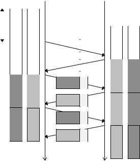
The basic frame exchange for real-time audio data is described as follows.
|
|
Device A |
|
|
|
Device B |
|
||||||||
|
|
|
|
|
|
|
|
|
|
|
|
|
|
|
|
|
|
TX |
R X |
|
|
|
TX |
R X |
|||||||
|
|
Buffer |
Buffer |
|
|
|
Buffer |
Buffer |
|||||||
|
|
|
|
|
|
|
|
|
|
|
|
|
|
|
|
|
|
|
|
|
|
|
|
|
|
|
|
|
|
|
|
20ms |
|
A1 |
|
|
|
|
|
|
|
|
|
|
|
|
|
|
|
|
|
|
|
|
|
IrLAP Frame |
|
|
|
|
|
|
|
|
|
|
|
|
|
|
|
|
|
|
B1 |
|
A0 |
|
|
|
|
|
|
|
|
|
|
A1 |
C |
|
|
|
|
||
|
|
|
|
|
|
|
|
||||||||
|
|
|
|
|
|
|
|
|
|
|
|
|
|
||
|
|
A2 |
|
|
B0 |
|
|
|
|
|
|
|
|
|
|
|
|
|
|
|
|
|
|
B1 |
C |
|
|
|
|
|
|
|
|
|
|
|
|
|
|
|
|
|
B2 |
A1 |
|||
|
|
|
|
|
|
|
|
|
|
||||||
|
|
|
|
|
|
|
|
|
|
|
|||||
A2 C
A3 B1
B2 C
B3 A2
A3 C
A4 B2
B3 C
B4 A3
Figure 12-2 Normal Transmission Operation
In RTCON, both audio and control data are stuffed into one frame, and transferred to TinyTP.
12.2.1 Real-time Voice Data Management (RTCON operation) Overview
Phones have standby and talk modes. RTCON also has these modes. When a phone changes from talk mode to standby mode, RTCON also changes from talk mode to standby mode. RTCON is forced to change its mode by RTCON_status.request (refer to 11.4.7) from the upper application. The upper application issues RTCON_status.request when it detects the Call Control “+CTALK” or “+CTONE” command. RTCON is just a pipe-line for audio and control data, it does not decode or change the data that it transfers. So, RTCON mode is managed by the upper application.
[RTCON standby mode] In this mode, there is only control data in the RTCON link between the phone and the cradle/PC. When the upper application issues control data, RTCON immediately sends a frame, in which the control data is included.
[RTCON talk mode] In this mode, there is both audio and control data in the RTCON link, between the phone and cradle/PC. RTCON sends a frame, in which both audio and control data is included, every 20 ms. When the upper application issues control data, the control data is not sent immediately, but is delayed until the next 20ms slot.
In addition, RTCON should have a procedure for the occurrence of errors as described below.
12.2.2 Factors of Errors
There are three causes of error, first is CRC error detection, the second is clock slip and the third is instability of Indication arrival timing. When one of these errors occurs, there may be an overflow, or underflow of data to/from the codec circuit. Overflow data should be discarded. In an underflow condition, the codec circuit
134
Specifications forIr Mobile Communications(IrMC) |
Version 1.1 |
should be given dummy data, to allow decoding to continue. The detailed RTCON procedure is described in 11.7.
(1) DETECTION OF FCS ERROR
If a CRC error is detected by the IrLAP layer, or if the physical layer SIR does not receive any data, then IrLAP does not have any audio or control data to transfer to RTCON. The audio and control data that is waiting to be sent by RTCON, cannot be transmitted, as its transmission is normally triggered by the reception of data from the other device.
Therefore, the codec circuit cannot be supplied data to decode, and the generated data by the codec circuit, cannot be sent during this error period.
(2) CODEC CLOCK SLIP
As the ADPCM sampling codecs between the primary and secondary stations are not synchronized with each other, clock slip is caused by the difference in the accuracy of their clocks.
- In the case that the Secondary clock is faster than the Primary.
The secondary will have more speech data to transmit, than the primary is expecting. Similarly, the secondary will use up the speech data faster than the primary transmits it.
In the transmission part of the secondary station, the secondary will be ready to transmit the data before it receives the indication to transmit from the primary. As the data is ready to transmit before it is transmitted, the delay between sampling the speech and the other end receiving it, is extended.
Eventually this will lead to the situation when there are two send-requests pending, when the indication to transmit is received from the primary. When this happens, the last send-request, might be dropped. Speech data may be lost. It is implementation specific how this error situation is handled.
If the difference between the clocks is small, then this will not happen very often.
In the reception part of the secondary station, the codec will be expecting data faster than the primary is sending it. Eventually the buffer which supplies the codec, will underflow. When this happens, dummy speech data should be sent to the codec. This occurs at the same rate as in the transmission part.
-In the case that the secondary clock is slower than the primary.
The primary will have more speech data to transmit, than the secondary is expecting. Similarly, the primary will use up the speech data faster than the secondary transmits it.
In the transmission part of the secondary station, the secondary will not be ready to transmit the speech data when it receives the indication to transmit from the primary. When this happens, the secondary IrLAP has to send an RR frame to the primary station. No speech data is sent.
When the primary sends the next indication to transmit, the speech data that was too late last time, will now be ready. Eventually the error condition will occur again.
If the difference between the clocks is small, then this will not happen very often.
In the reception part of the secondary station, the buffer which supplies the codec will not be empty when the next frame arrives. Eventually the buffer which supplies the codec, will overflow. When this happens, speech data may be lost. It is implementation specific how this error situation is handled.
This occurs at the same rate as in the transmission part.
(3) INSTABILITY OF INDICATION ARRIVAL TIMING
The IrLAP frame size is variable depending on the control data size (0-6 bytes). In addition, if the escape sequence code (C0, C1, 7D) is in the I field of the IrLAP frame, then the IrLAP frame size becomes longer due to the transparent nature of IrLAP. Therefore, the Indication arrival timing is dispersed (it occurs an Indication arrives earlier than expected and an Indication arrives than expected at random.). This is the similar situation to the clock slip explained above and shortens the clock slip interval.
135
Specifications forIr Mobile Communications(IrMC) |
Version 1.1 |
12.2.3 RTCON Primary / Secondary Role
When RTCON executes a primary procedure, its local IrLAP should act as primary station. Similarly, when RTCON is executing a secondary procedure, its local IrLAP should act as a secondary station.
If RTCON tries to execute a procedure which does not correspond with its local IrLAP role, it will not work. To deal with this case, it is recommended that RTCON has a primary/secondary exchange procedure as described in 12.6.1, in order to correct the IrLAP role.
12.2.4 Negotiation Parameters
- Baud rate |
115200 bps (note 1) |
- Max turn around time |
(=>) 50 ms (note 2) |
- Window size |
1 (note1) |
- Data Size |
(=>) 128 byte (note 2) |
- Additional BOFs |
0 |
- Minimum turn around time |
(<=) 0.5 ms (note 3) |
note 1: When RTCON is on talk mode, these values should be set as shown.
note 2: It is possible to set longer values for these parameters, but in that case recovery takes more time when a CRC check error occurs.
note 3: This parameter is defined as the required time delay between the last byte of the last frame sent by a station and the point at which it is ready to receive the first byte of a frame from another station (refer to 6.6.8 in the IrLAP specification). The IrDA device (including CPU) may need a certain time for receipt-frame processing between receiving the frame at the Physical layer and sending an Indication to the upper layer at IrLAP. Therefore, in this document, Minimum turn around time means the period from receiving a frame at the Physical layer to sending a frame at IrLAP (including frame processing time).
The minimum turn around time has been reduced to 0.5ms, to support the timing requirements of full duplex audio. The IrDA frames for audio are 96 bytes long. This includes 80 bytes for the 32kbps ADPCM and 6 bytes of control data. The frame length may be extended with additional bytes added for byte stuffing. On average, this will be one extra byte. At 115200bps, it takes 8.4ms to transmit an average frame ( 96+1 bytes ). To support full duplex speech, one frame must be transmitted and one frame received every 20ms. This leaves on average 1.6ms to turn the link around. The 0.5ms receiver latency allowance in the physical layer rev. 1.2a is required, so that the link would not fail, if more than the average 1 byte of byte stuffing was required.
It should be noted that the IrDA physical layer implementations using receiver latency allowances of greater than 0.5ms will not be able to support the audio feature. That is, 0.5ms is the maximum allowable value for the minimum turn around time.
12.3 Frame Format
The IrLAP frame structure is shown as below.
The flag is at the beginning of the service data field. This gives information about the contents of the following data.
The data length of ITU-T G.726 32kbps ADPCM in the service data field is fixed (80 bytes). For other codecs the data field length depends on implementation (max. 80 bytes). The control data length is variable (0-6 bytes). During standby mode, there is only control data following the flag in the service data field.
136

Specifications forIr Mobile Communications(IrMC) |
Version 1.1 |
IrLAP frame structure
Service data
BOF |
A |
C |
Header |
flg |
ADPCM / other codec |
Control |
FCS |
E O F |
|
|
|
|
1+ |
80bytes |
0-6bytes |
|
|
|
Note1 |
Note2 |
byte |
Data field |
Control field |
|||
|
|
|||||||
Note1: indicates I frame
Note2: includes DLSAP, SLSAP, Credit
Figure 12-3
Flag (Flg) field
Flag
|
|
|
1byte |
1byte |
|
1byte |
PL byte |
|
|
|
|
|
|
|
|
|
|
|
|
|
|
|
|||||||
|
|
|
PN=X |
|
PI |
|
PL |
|
PV |
|
PI |
PL |
|
PV |
…. |
|
PI |
|
PL |
|
PV |
|
|||||||
|
|
|
|
|
|
|
|
|
|
|
|
|
|
|
|
|
|
|
|
|
|
|
|
|
|||||
|
|
|
|
|
|
Extended Parameter 1 |
|
Extended Parameter 2 |
|
|
|
Extended Parameter X |
|
|
|||||||||||||||
|
|
|
|
|
|
|
(if present) |
|
|
|
|
|
(if present) |
|
|
|
|
(if present) |
|
|
|
||||||||
|
|
|
|
|
|
|
|
|
|
|
|
|
|
|
|
|
|
|
|
|
|
|
|
|
|
(Max.7) |
|||
|
|
|
|
|
|
|
|
|
|
|
|
|
|
|
Figure 12-4 |
|
|
|
|
|
|
|
|
|
|
|
|||
- 1st byte of Flag field |
|
|
|
|
|
|
|
|
|
|
|
|
|
|
|
|
|
|
|
|
|
|
|
||||||
|
|
|
|
|
|
|
|
|
|
|
|
|
|
|
|
|
|
|
|||||||||||
|
Bit |
|
|
|
Function |
|
|
Value |
|
|
|
Description |
|
|
|
|
|
Default |
|||||||||||
|
7 |
|
|
Data field |
|
|
|
|
|
0 |
|
None |
|
|
|
|
|
|
|
|
0 |
|
|
|
|
||||
|
|
|
|
|
|
|
|
|
|
|
|
1 |
|
Present |
|
|
|
|
|
|
|
|
|
|
|
|
|
||
|
6 |
|
|
0 |
|
|
|
|
|
|
|
0 |
|
(Fixed) |
|
|
|
|
|
|
|
|
0 (fixed) |
||||||
|
5 |
|
|
Control filed type |
|
|
0 |
|
Standard (Call Control data) |
|
|
|
|
0 |
|
|
|
|
|||||||||||
|
|
|
|
|
|
|
|
|
|
|
|
1 |
|
Other |
|
|
|
|
|
|
|
|
|
|
|
|
|
||
|
|
|
|
|
|
|
|
|
|
|
|
|
|
|
(operator/manufacturer specific) |
|
|
|
|
|
|
|
|
||||||
|
4-3 |
|
|
rsvd |
|
|
|
|
|
|
|
|
|
|
|
|
|
|
|
|
|
|
|
0 |
|
|
|
|
|
|
2-0 |
|
|
PN |
|
|
|
|
|
|
0-7 |
|
Number of Extended Parameters |
|
|
|
0 |
|
|
|
|
||||||||
-In the case that there is no DATA field in the frame, the Data field is “None”.
-In the case that the data in the Control field is not Call Control, Control field type is ‘Other’.
-If any other detailed information about IrLAP frames is needed, the detailed information can be indicated in Extended Parameters.
-Extended Parameters
DATA/Control field extended Common attribute
PI |
PI name |
PL |
PV data type |
|
PV description |
0x00 |
Audio field length |
1 |
|
0-255 byte |
length |
0x01 |
rsvd |
|
|
|
|
- |
|
|
|
|
|
0x0F |
|
|
|
|
|
137

Specifications forIr Mobile Communications(IrMC) |
|
|
|
|
|
|
|
|
|
|
|
|
|
|
|
|
|
Version 1.1 |
|||||||||||||
DATA/Control field Operator/Manufacturer specific attribute |
|
|
|
|
|
|
|
|
|
|
|
|
|
|
|
|
|||||||||||||||
|
|
|
|
|
|
|
|
|
|
|
|
|
|
|
|
|
|
|
|
|
|
|
|
|
|
|
|
|
|
|
|
|
PI |
PI name |
|
PL |
|
PV data type |
|
|
|
|
|
|
|
|
|
|
|
|
|
|
PV description |
||||||||||
|
0x10 |
(Operator category) |
|
2+ |
|
(Operator code) |
|
|
|
|
|
|
|
|
|
|
|
|
undefined |
||||||||||||
|
~ |
0x10=Japan |
|
|
|
|
|
|
|
|
|
|
|
|
|
|
|
|
|
|
|
|
|
|
|
|
|
|
|
|
|
|
0xAF |
|
|
|
|
|
|
|
|
|
|
|
|
|
|
|
|
|
|
|
|
|
|
|
|
|
|
|
|
|
|
|
0xF0 |
Manufacturer specific |
|
|
|
|
|
|
|
|
|
|
|
|
|
|
|
|
|
|
|
|
|
|
|
|
undefined |
||||
|
~ |
|
|
|
|
|
|
|
|
|
|
|
|
|
|
|
|
|
|
|
|
|
|
|
|
|
|
|
|
|
|
|
0xFF |
|
|
|
|
|
|
|
|
|
|
|
|
|
|
|
|
|
|
|
|
|
|
|
|
|
|
|
|
|
|
NOTE: No octet can be set with a control sequence code such as C0, C1 and 7D. |
|
|
|
||||||||||||||||||||||||||||
ADPCM Bit Ordering |
|
|
|
|
|
|
|
|
|
|
|
|
|
|
|
|
|
|
|
|
|
|
|
|
|
|
|
|
|||
|
|
ADP CM sample |
|
|
|
|
4bit |
4bit |
|
4bit 4bit |
|
|
|
|
|
|
|
|
|||||||||||||
|
|
|
|
|
|
|
|
|
|
|
|
|
|
|
|
|
|||||||||||||||
|
|
|
|
|
|
|
0 |
|
|
1 |
|
|
|
2 |
|
|
|
|
3 |
|
|
|
|
|
|
|
|
||||
|
|
|
|
|
|
|
|
|
|
|
|
|
|
|
|
|
|
|
|
|
|
|
|
|
|
|
ti m e |
|
|
||
|
|
|
|
|
|
|
|
|
|
|
|
|
|
|
|
|
|
|
|
|
|
|
|
|
|
|
|
|
|||
|
|
|
|
|
|
|
|
|
|
|
|
|
|
|
|
|
|
|
|
|
|
|
|
|
|
|
|
|
|||
|
|
|
|
|
|
|
|
|
|
|
|
|
|
|
|
|
|
|
|
|
|
|
|
|
|
|
|
||||
|
|
|
|
|
|
|
|
d03 |
d02 |
d01 |
|
d00 |
|
|
|
|
|
|
|
|
|
|
|
||||||||
|
|
|
|
|
|
|
|
|
|
|
|
|
|
|
|
|
|
|
|
|
|
|
|
|
|
|
|
||||
|
|
|
|
|
|
M SB |
|
|
|
|
|
|
LS B |
|
|
|
|
|
|
|
|
|
|
||||||||
|
|
B it O d erin g in RT CO N |
sam ple0 |
|
|
|
|
|
|
|
sam ple1 |
|
|
||||||||||||||||||
|
|
|
|
|
|
|
|
|
|
|
|
|
|
|
|
|
|
|
|
|
|||||||||||
|
|
|
|
|
|
|
|
|
|
|
|
|
|
|
|
|
|
|
|
|
|||||||||||
|
|
|
|
|
|
|
|
|
|
|
|
|
|
|
|
|
|
|
|
|
|
|
|
|
|
|
|
|
|
|
|
|
|
|
|
|
|
|
|
|
d03 |
d02 |
|
d01 |
d00 |
|
d13 |
d12 |
|
d11 |
d10 |
|
|||||||||||
|
|
|
|
|
|
|
|
|
|
|
|
|
|
|
|
|
|
|
|
|
|
|
|
||||||||
|
|
|
|
|
7 |
|
|
6 |
|
|
5 |
|
4 |
|
3 |
2 |
|
1 |
0 |
|
|||||||||||
|
|
|
|
|
|
|
|
M SB |
|
|
|
|
|
|
|
|
|
|
|
|
|
|
|
|
|
|
LS B |
||||
Figure 12-5
An ADPCM sample (4 bit) is generated in the ADPCM codec, and a series of two samples composes one byte. In one-byte data, the first sample is the upper 4 bits and the following sample is the lower 4 bits.
There are 5 patterns of service data field dependent on portable phone mode.
(1) STANDBY MODE
BOF |
A |
C |
Header |
flg |
Control |
FCS |
EOF |
|
|
|
|
1byte |
1-86bytes |
|
|
- Control Field: 1 ~ 86 bytes (variable)
138