

ethwm21e-1
.pdfEthernut Hardware Manual
Board Installation
1 Remove the board from the antistatic bag. Visually inspect the board to verify that it was not damaged during shipment. Do not use the antistatic bag as a underlying pad for Ethernut, because it’s electroconductive. Put the board on a wooden surface or simply on a piece of paper. Plastic surfaces may be harmful because of electrostatic discharge.
WARNING: As with all computer equipment, the Ethernut board may be severely damaged by electrostatic discharge (ESD). Be sure to take proper precautions before removing the Ethernut board from the antistatic bag. Never pass the board from one person’s hand to another.
2Connect Ethernut`s DB-9 RS232 port to an available COM port using the serial cable.
3Use one twisted pair cable to connect Ethernut's RJ-45 connector to the hub or switch and the other twisted pair cable to connect the hub or switch with the network adapter in the PC. If you are not using a hub or switch, then directly connect the Ethernut board with the PC’s network adapter using a twisted pair cross cable.
4Connect the power supply to the barrel connector on the Ethernut board. The Ethernut board is equipped with its own rectifier bridge and voltage regulator. Therefore the polarity of the barrel connector isn't important.
WARNING: The power supply should not be plugged into an electrical outlet before connecting it to the Ethernut board.
5Apply power to the Ethernut board by connecting the power supply to an electrical outlet. When the board is powered up, the red power LED (LED1) should go on.
6Start the terminal emulation program at 38400 baud or any higher rate up to 115200 baud, no parity, 8 data bits, and 1 stop bit. Disable hardware (RTS/CTS) and software (XON/XOFF) flow control.
8

Quick Start
Baudrate
The baudrate of the Ethernut board is specified by the CPU crystal (Q1, 14.7456 MHz by default) and a baudrate selector ranging from 0 to 255.
The actual baudrate can be calculated by
baudrate = crystal frequency / (16 * (selector + 1))
Running at 14.7456 MHz, a selector value of 23 gives a baudrate of 38400
Baud:
38400 = 14745600 / (16 * (1 + 1))
The Basemon program provides a simple automatic baudrate selection by changing the selector from zero to 71, while trying to receive a space character. If no space character could be received within about a minute, then the default selector 23 is set (38400 Baud at 14.7456 MHz).
7 Reset the Ethernut board by depressing and releasing the reset switch located near the SMSC chip. Hold down the spacebar on the terminal emulation program and wait until the BaseMon welcome message is displayed.
See the next chapter for a detailed description of the BaseMon program.
9
Ethernut Hardware Manual
Testing the Board
Using the preloaded BaseMon firmware to test the Ethernut hardware.
When using a terminal emulation program like described in the previous chapter, hold down the space bar on the PC keyboard and press and release the reset button on the Ethe
rnut board. This is the tiny push button at the board’s edge near the screw terminal. After some seconds the following output should appear in the terminal emulation window:
BaseMon |
4.0.2 |
|
|||
Nut/OS |
3.4.2.1 |
|
|||
Baudrate |
select = |
23 |
|||
External RAM Test... 44800 bytes |
|||||
Banked |
RAM Test... |
30 banks, 16384 bytes ea. |
|||
Detecting |
NIC... |
LAN91C111 |
|||
Testing |
NIC... |
OK |
|||
I/O |
Port |
Test... |
OK |
||
Press any of the following keys: |
|||||
B |
- |
Send |
broadcasts |
||
E - Ethernet controller read/write |
|||||
J - Jump to bootloader |
|||||
S |
- |
SRAM |
read/write |
||
X |
- |
Exit |
BaseMon, |
configure network and start WebServer |
|
Depending on the preloaded version and the baudrate, your output may slightly differ. But the amount of RAM should match and all tests should report the result OK.
The menu will not appear, if BaseMon didn’t receive a space character or failed to determine the baudrate. Check again the configuration of the terminal emulation program and make sure that all handshakes are disabled. Sometimes the keyboard repeat rate of the PC is too slow, in which case BaseMon isn’t able to verify the baudrate. If you don’t know how to increase this rate, thumb on the space bar as fast as you can. Replacing the Beethoven sound from your MP3 player by a record from Metallica or Pantera will be helpful.
Nevertheless, if BaseMon is unable to receive three consecutive space characters at the same baudrate, it will continue at 38,400 Baud. In this case it will not display the menu, nor wait for any further input, but display the test results and then immediately start the build-in webserver.
Unlike some other embedded monitors, BaseMon is not resident. You will later upload other sample applications or your own code, which overwrite BaseMon. Whenever you are not sure, whether any problems may arise from hardware or software failures, it’s always a good idea to upload the BaseMon hex file again for running the integrated tests. The menu offers further tests, which will be described now.
10
Testing the Board
Ethernet Controller Read/Write Loop
When pressing E on the BaseMon menu, the Ethernut board will enter an endless loop, trying to read the revision ID of the Ethernet controller at base address C000 hex:
rev=0x91
The loop keeps running until a key is pressed in the terminal emulation program and may be used to check the board's address and data bus signals with an oscilloscope or logic analyzer.
Jump to Bootloader
When pressing J on the BaseMon menu, the program will jump to flash memory location 1F000 hex. Fully assembled Ethernut boards are delivered with a preloaded bootloader, which uses DHCP/BOOTP/TFTP to load a new flash ROM image. Note, that the bootloader will be deleted by the chip erase command, which is typically required before uploading a new application.
SRAM Read/Write Loop
When pressing S on the BaseMon menu, the Ethernut board enters an endless loop, doing a walking bit test on all address and data bus lines. The loop keeps running until a key is pressed in the terminal emulation program and may be used to check the board's address and data bus signals with an oscilloscope or logic analyzer.
Send Broadcasts Loop
When pressing B on the BaseMon menu, the Ethernut board will initialize the Ethernet Controller and start sending Ethernet broadcasts in an endless loop. The yellow link LED will lit and the green activity LED will start flashing. The terminal emulation window will show the progress. The loop keeps running until a key is pressed in the terminal emulation program and may be used to check the board's Ethernet output with an oscilloscope.
Exit BaseMon
Pressing X on the BaseMon menu will quit the BaseMon program, initialize the Nut/OS operating system and Nut/Net TCP/IP stack and finally enter a sample HTTP daemon application. However, before that is done, BaseMon queries a MAC address, IP address, network mask and default route:
MAC address (000698000000):
IP address (0.0.0.0):
Net mask (255.255.255.0):
Default route (0.0.0.0):
The last six digits of the MAC address are written on the board. Enter these six digits on the MAC address prompt. On all prompts, you may simply press enter to confirm the default shown in brackets, or enter other values in their decimal dotted form. If the IP address is 0.0.0.0, Ethernut will not query the network mask and default route, but request these values from a DHCP server. This requires of course, that a DHCP server is running in your local network.
Network configuration is discussed in more detail in the next chapter.
11

Ethernut Hardware Manual
Network Configuration
This chapter shows different methods to configure Ethernut`s network parameters.
In order to communicate over a TCP/IP network, the Ethernut board needs a unique IP address. It is important, that this address is not used by any other node on the network.
Changing the network configuration requires user interaction, either by keyboard/LCD interface, web browser, RS-232 communication or whatever the final system may provide. It’s up to the specific application to deal with these values. Nut/OS just provides a common framework. The BaseMon application explained in the previous chapter uses RS-232, for example.
The TCP/IP configuration is stored in EEPROM and contains the following values (Nut/OS Version 4.2).
Name |
Type |
Default |
Description |
|
||||||
|
|
|
|
Total |
size |
of |
the |
|||
size |
Byte value |
31 |
configuration |
structure. |
||||||
|
|
|
|
Used |
to |
check |
validity. |
|||
|
|
|
|
|
|
|
||||
|
Character |
|
Name |
of |
the network |
|||||
name |
eth0 |
interface. Maximum size is |
||||||||
array |
||||||||||
|
|
8 |
characters. |
|
||||||
|
|
|
|
|
||||||
|
|
|
|
|
|
|
||||
mac |
Byte array |
000698000000 |
6 |
bytes |
unique MAC |
|||||
address. |
|
|
|
|||||||
|
|
|
|
|
|
|
||||
|
|
|
|
|
|
|
|
|||
ip_addr |
IP |
address |
0.0.0.0 |
Last |
used |
IP |
address. |
|||
|
|
|
|
|
|
|
||||
ip_mask |
IP |
address |
255.255.255.0 |
Configured |
IP |
mask. |
||||
|
|
|
|
|
|
|||||
gateway |
IP |
address |
0.0.0.0 |
Default |
gateway IP. |
|||||
|
|
|
|
|
|
|
||||
cip_addr |
IP |
address |
0.0.0.0 |
Configured |
IP |
address. |
||||
|
|
|
|
|
|
|
|
|
|
|
Default values will be used by the software when the EEPROM has been previously erased. When Ethernuts are shipped, the EEPROM contains the values from the final test. The last used IP address is set to 192.168.192.x, with x varying between 100 and 254. The MAC address will be the one, that has been uniquely assigned to your board. You can find it in your invoice too and the last six digits are written on the board. The configured IP address is set to 0.0.0.0, which automatically enables DHCP.
A MAC address, also referred to as the hardware or Ethernet address is a unique 48 bit number assigned to every Ethernet node. The upper 24 bits are the manufacturer's ID, assigned by the IEEE Standards Office. The ID of Ethernut boards manufactured by egnite Software GmbH is 000698 hexadecimal. The lower 24 bits are the board's unique ID assigned by the manufacturer of the board. Boards produced by egnite do have a unique ID, which is written on the board.
12
Network Configuration
The ATmega 128 microcontroller offers a number of programmable flags to change general modes. One of these flags disables EEPROM erasure during chip erase and has been set before shipping the board. Thus, if the chip is erased in order to upload a new application, the EEPROM contents is preserved and reused by the new application.
DHCP/BOOTP Method
This is the preferred method. As explained, the configured IP of shipped Ethernuts is set to 0.0.0.0, which enables DHCP/BOOTP. If a DHCP server exists on the network, Ethernut will automatically request its IP address, the IP address of the standard gateway, and the IP mask of the local network. If no DHCP server could be located, the board will reuse the last used address. If this is 0.0.0.0 or if the EEPROM had been erased, then Ethernut switches to the ARP method.
Fixed IP Address
If DHCP service is not available, you should assign a fixed IP address. Before you create your own applications with fancy user interfaces to set this address, you can use BaseMon. The EEPROM configuration will be preserved when reprogramming the Ethernut and will be reused by the new applications.
ARP Method
This method can be used as a last resource. If the Ethernut's EEPROM contains no configuration data and no DHCP server is available on the network, then the ARP method may be helpful to set the board's IP address. In this mode the Ethernut board set its address from the first ICMP packet it receives.
To set the Ethernut's IP address by the ARP method, an ARP entry can be manually created on the PC and then a ping packet is sent from the PC to the Ethernut board.
Enter the following command to manually create an ARP entry for an Ethernut board with a MAC address of 00:06:98:00:00:00 and an IP address of 192.168.171.5 on a LINUX command line shell:
arp -s 192.168.171.5 00:06:98:00:00:00
On a Windows DOS prompt this command is slightly different:
arp -s 192.168.171.5 00-06-98-00-00-00
The next command to enter is the same on both systems:
ping 192.168.171.5
The first ping packet that arrives at the Ethernut board with the MAC address of 00:06:98:00:00:00 sets the IP address of that board to 192.168.171.5. Note, that the ARP method will not configure a default gateway and will fix the network mask to 255.255.255.0.
The ARP method will be used on blank EEPROMs only. After having set it once, the configuration will be stored in the EEPROM and used in the next system start. To enable the ARP method again, you must use your JTAG programmer to clear the EEPROM contents. Refer to the Ethernut Software Manual for further information about JTAG programming.
13
Ethernut Hardware Manual
Testing Network Operation
After configuring the network parameters, you can check, that the Ethernut board is properly hooked up to the network by running ping from your PC. On a DOS prompt or command line shell, type:
ping 192.168.171.5
Instead of the above IP address use the one you configured previously. If you receive a response without timing out, the Ethernut board is ready to try the HTTP daemon. Use any Webbrowser to query the following URL:
http://192.168.171.5/index.html
Again, instead of the above IP address use the one previously configured.
14

Jumper Configuration
Jumper Configuration
Adapting Ethernut to specific requirements.
Jumper Overview
For maximum flexibility, the board is equipped with 5 jumper areas. The picture below shows the default jumper configuration, set when Ethernuts is shipped.
JP1 configures the connection to the two serial devices (UART). JP2 is used to select the port bit of the RS485 direction signal. JP3 enables power supply over Ethernet cable.
JP5 is used to specify the JTAG chain. JP6 configures the RS485 screw terminal.
JP4 had been used on previous board revisions to select between ISP and JTAG programming. Ethernut 2.1 doesn’t provide an ISP connector and thus JP4 had been removed.
Note, that in the following pictures pin 1 is always the one in front on the left side.
Serial Ports
Ethernut provides an on-board DB-9 connector for RS-232 serial communication as well as a screw terminal for RS-485 half duplex communication. IC6 is used to convert the required voltage levels for RS-232 from the 5V power supply, while IC7 provides the signal conversion for the RS-485 interface.
Both, the RS-232 or the RS-485 connector may be connected to the first (UART0) or the second (UART1) serial device of the ATmega128. This is configured by jumper JP1.
15
Ethernut Hardware Manual
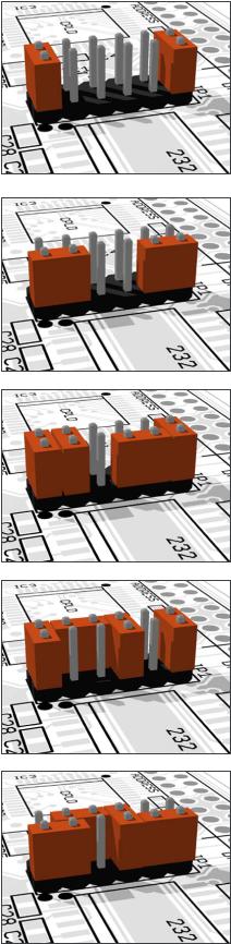
JP1 Shortening pins 1 and 2 and pins 11 and 12 will route UART0 transmit and receive lines to the DB-9 connector.
JP1 When pins 1 and 3 and pins 9 and 11 are shortened, then UART1 is connected to the DB-9 connector.
JP1 Even both UARTs can be routed to the DB-9 connector when shortening pins 1 and 2, 3 and 4, 7 and 9 and 11 and 12. However, a special adapter is required to route the UART1 transmit line from the onboard DB-9 pin 7 to a second DB-9 pin 3 and the receive line from the onboard DB-9 pin 8 to pin 2 of the second connector.
JP1 If your application requires hardware handshake via RTS/CTS, then connect JP1 pins 4 and 6 and pins 5 and 7. The picture on the right shows the hardware handshake configuration for UART0.
JP1 Hardware Handshake can also be used, if UART1 is routed to the RS-232 interface.
16
Jumper Configuration
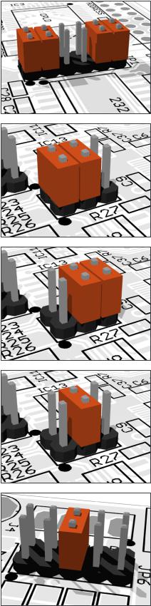
JP1 Most applications will probably use UART0 for RS-232 and UART1 for RS-485. This configuration is shown below. Pins 1 and 2, 3 and 4, 9 and 10 and 11 and 12 of JP1 are shortened.
JP2 The RS-485 interface is half duplex. Only two wires are needed for communication, but an additional port bit is required to switch between receive and transmit mode. Thus pins 1 and 2 as well as pins 3 and 4 of JP2 must be shortened to control the data direction via ATmega port bit PD5.
JP2 Shortening pins 5 and 6 instead of pins 1 and 2 will use port bit PD4.
JP2 The direction signal is pulled low by R27. If pins 3 and 4 are shortened only, the RS-485 interface is configured as a receiver and no port bit for direction control is required.
JP6 Both ends of a RS-485 communication line must be terminated by a resistor. If the Ethernut board is located at one end of the line, you must short pins 5 and 6 of JP6 to enable the 120 Ohm termination resistor (R24).
17