

What is a Microcontroller (Paralax, v2.2, student guide, 2004)
.pdfChapter #5: Measuring Rotation · Page 143
turn the potentiometer’s input shaft, the resistance between the A and W terminals changes. This in turn changes the current flow through the LED circuit.
ACTIVITY #2: MEASURING RESISTANCE BY MEASURING TIME
This activity introduces a new part called a capacitor. A capacitor behaves like a rechargeable battery that only holds its charge for short durations of time. This activity also introduces RC-time, which is an abbreviation for resistor-capacitor time. RC-time is a measurement of how long it takes for a capacitor to lose a certain amount of its stored charge as it supplies current to a resistor. By measuring the time it takes for the capacitor to discharge with different size resistors and capacitors, you will become more familiar with RC-time. In this activity, you will program the BASIC Stamp to charge a capacitor and then measure the time it takes the capacitor to discharge through a resistor.
Introducing the Capacitor
Figure 5-7 shows the schematic symbol and part drawing for the type of capacitor used in this activity. Capacitance value is measured in microfarads ( F), and the measurement is typically printed on the capacitors. The cylindrical case of the capacitor is called a canister.
This capacitor has a positive (+) and a negative (-) terminal. The negative terminal is the lead that comes out of the metal canister closest to the stripe with a negative (–) sign. Always make sure to connect these terminals as shown in the circuit diagrams. Connecting one of these capacitors incorrectly can damage it. In some circuits, connecting this type of capacitor incorrectly and then connecting power can cause it to rupture or even explode.
3300 µF
|
3 |
Figure 5-7 |
|
3300 F Capacitor |
|
|
3 |
|
|
0 |
Schematic Symbol |
|
0 |
|
|
µ |
and Part Drawing |
|
F |
|
|
|
Pay careful attention |
+ |
- |
to the leads and how |
they connect to the |
||
|
|
Positive and |
Negative Terminals.
Page 144 · What’s a Microcontroller?
Resistance and Time Parts
(1) Capacitor – 3300 µF
(1) Capacitor – 1000 µF
(1) Resistors – 220 Ω (red-red-brown)
(1) Resistor – 470 Ω (yellow-violet-brown)
(1) Resistor – 1 kΩ (brown-black-red)
(1) Resistor – 2 kΩ (red-black-red)
(1) Resistor – 10 kΩ (brown-black-orange)
Recommended Equipment: Safety goggles or safety glasses.
Building and Testing the Resistance Capacitance (RC) Time Circuit
Figure 5-8 shows the circuit schematic and Figure 5-9 shows the wiring diagram for this activity. You will be taking time measurements using different resistor values in place of the resistor labeled Ri.
SAFETY
Always observe polarity when connecting the 3300 F capacitor. Remember, the negative terminal is the lead that comes out of the metal canister closest to the stripe with a negative (–) sign. Use Figure 5-7 to identify the (+) and (-) terminals.
Your 3300 F capacitor will work fine in this experiment so long as you make sure that the positive (+) and negative (-) terminals are connected EXACTLY as shown in Figure 5-8 and Figure 5-9.
Never reverse the supply polarity on the 3300 F or any other polar capacitor. The voltage at the capacitor’s (+) terminal must always be higher than the voltage at its (-) terminal. Vss is the lowest voltage (0 V) on the Board of Education and BASIC Stamp HomeWork Board. By connecting the capacitor’s negative terminal to Vss, you ensure that the polarity across the capacitor’s terminals will always be correct.
Wear safety goggles or safety glasses during this activity.
Always disconnect power before you build or modify circuits.
Keep your hands and face away from this capacitor when power is connected.
√With power disconnected, build the circuit as shown starting with a 470 Ω resistor in place of the resistor labeled Ri.

Chapter #5: Measuring Rotation · Page 145
P7 


 220 Ω
220 Ω
3300 µF
R4 R3 R2
Vdd
X3


P15 

P14 
P13 

P12 
P11 

P10 
P9
P8
P7
P6
P5
P4
P3
P2
P1
P0
X2
R1 = 470 Ω
Ri R2 = 1 kΩ
R3 = 2 kΩ
R4 = 10 kΩ
Vss
R1 |
|
|
|
|
|
|
|
- |
|
0 |
|
F |
|
Vin Vss |
|
µ |
||||
|
|
3 |
0 |
|
||
|
|
3 |
|
|
|
|
|
|
+ |
|
|
|
|


 +
+
Figure 5-8
Schematic for Viewing RC-time Voltage Decay
Four different resistors will be used as Ri shown in the schematic. First, the schematic will be built and tested with Ri = 470 Ω, then Ri = 1 kΩ, etc.
Figure 5-9
Wiring Diagram for Figure 5-8
Make sure that the negative lead of the capacitor is connected on your board the same way it is shown in this figure, with the negative lead connected to Vss.
Polling the RC-Time Circuit with the BASIC Stamp
Although a stopwatch can be used to record how long it takes the capacitor’s charge to drop to a certain level, the BASIC Stamp can also be programmed to monitor the circuit and give you a more reliable time measurement.
Example Program: PolledRcTimer.bs2
√Enter and run PolledRcTimer.bs2.
√Observe how the BASIC Stamp charges the capacitor and then measures the discharge time.

Page 146 · What’s a Microcontroller?
√Record the measured time (the capacitor’s discharge time) in the 470 Ω row of Table 5-1.
√Disconnect power from your Board of Education or BASIC Stamp HomeWork Board.
√Remove the 470 Ω resistor labeled Ri in Figure 5-8 and Figure 5-9 on page 145, and replace it with the 1 kΩ resistor.
√Reconnect power to your board.
√Record your next time measurement (for the 1 kΩ resistor).
√Repeat these steps for each resistor value in Table 5-1.
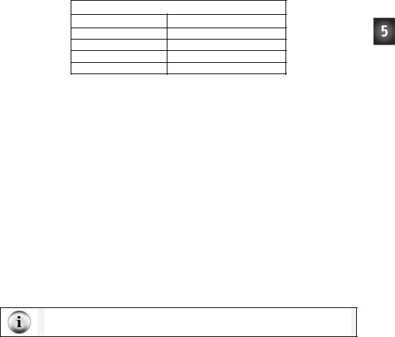
Table 5-1: Resistance and RC-time for C = 3300 µF
Resistance (Ω) |
Measured Time (s) |
|
|
470
1k
2k 10 k
'What's a Microcontroller - PolledRcTimer.bs2
'Reaction timer program modified to track an RC-time voltage decay.
'{$STAMP BS2}
'{$PBASIC 2.5}
timeCounter |
VAR |
Word |
counter |
VAR |
Nib |
DEBUG CLS |
|
|
HIGH 7
DEBUG "Capacitor Charging...", CR
FOR counter = 5 TO 0
PAUSE 1000
DEBUG DEC2 counter, CR, CRSRUP
NEXT
DEBUG CR, CR, "Measure decay time now!", CR, CR
INPUT 7
DO
PAUSE 100
timeCounter = timeCounter + 1

Chapter #5: Measuring Rotation · Page 147
DEBUG ? IN7
DEBUG DEC5 timeCounter, CR, CRSRUP, CRSRUP
LOOP UNTIL IN7 = 0
DEBUG CR, CR, CR, "The RC decay time was ", DEC timeCounter, CR,
"tenths of a second.", CR, CR
END
How PolledRcTimer.bs2 Works
Two variables are declared. The timeCounter variable is used to track how long it takes the capacitor to discharge through Ri. The counter variable is used to count down while the capacitor is charging.
timeCounter |
VAR |
Word |
counter |
VAR |
Nib |
The command DEBUG CLS clears the Debug Terminal so that it doesn’t get cluttered with successive measurements. HIGH 7 sets P7 high and starts charging the capacitor, then a “Capacitor charging…” message is displayed. After that, a FOR…NEXT loop counts down while the capacitor is charging. As the capacitor charges, the voltage across its terminals increases toward anywhere between 2.5 and 4.9 V (depending on the value of Ri).
DEBUG CLS
HIGH 7
DEBUG "Capacitor Charging...", CR
FOR counter = 5 TO 0
PAUSE 1000
DEBUG DEC2 counter, CR, CRSRUP
NEXT
A message announces when the decay starts getting polled.
DEBUG CR, CR, "Measure decay time now!", CR, CR
In order to let the capacitor discharge itself through the Ri resistor, the I/O pin is changed from HIGH to INPUT. As an input, the I/O pin, has no effect on the circuit, but it can sense high or low signals. As soon as the I/O pin releases the circuit, the capacitor
Page 148 · What’s a Microcontroller?
discharges as it feeds current through the resistor. As the capacitor discharges, the voltage across its terminals gets lower and lower (decays).
INPUT 7
Back in the pushbutton chapter, you used the BASIC Stamp to detect a high or low signal using the variables IN3 and IN4. At that time, a high signal was considered Vdd, and a low signal was considered Vss. It turns out that a high signal is any voltage above 1.4 V. Of course, it could be up to 5 V. Likewise, a low signal is anything between 1.4 V and 0 V. This DO…LOOP checks P7 every 100 ms until the value of IN7 changes from 1 to 0, which indicates that the capacitor voltage decayed below 1.4 V.
DO
PAUSE 100
timeCounter = timeCounter + 1
DEBUG ? IN7
DEBUG DEC5 timeCounter, CR, CRSRUP, CRSRUP
LOOP UNTIL IN7 = 0
The result is then displayed and the program ends.
DEBUG CR, CR, CR, "The RC decay time was ",
DEC timeCounter, CR,
"tenths of a second.", CR, CR
END
Your Turn – A Faster Circuit
By using a capacitor that has roughly 1/3 the capacity to hold charge, the time measurement for each resistor value that is used in the circuit will be reduced by 1/3. In Activity #3, you will use a capacitor that is 10,000 times smaller, and the BASIC Stamp will still take the time measurements for you using a command called RCTIME.
√Disconnect power to your Board of Education or HomeWork Board.
√Replace the 3300 F capacitor with a 1000 F capacitor.
√Confirm that the polarity of your capacitor is correct. The negative terminal should be connected to Vss.
√Reconnect power.
Chapter #5: Measuring Rotation · Page 149
√Repeat the steps in the Example Program: PolledRcTimer.bs2 section, and record your time measurements in Table 5-2.
√Compare your time measurements to the ones you took earlier in Table 5-1. How close are they to 1/3 the value of the measurements taken with the 3300 µF capacitor?
Table 5-2: Resistance and RC-time for C = 1000 µF
Resistance (Ω) |
Measured Time (s) |
|
|
470
1k
2k 10 k
ACTIVITY #3: READING THE DIAL WITH THE BASIC STAMP
In Activity #1, a potentiometer was used as a variable resistor. The resistance in the circuit varied depending on the position of the potentiometer’s adjusting knob. In Activity #2, an RC-time circuit was used to measure different resistances. In this activity, you will build an RC-time circuit to read the potentiometer, and use the BASIC Stamp to take the time measurements. The capacitor you use will be very small, and the time measurements will only take a few milliseconds. Even though the measurements take very short durations of time, the BASIC Stamp will give you an excellent indication of the resistance between the potentiometer’s A and W terminals.
Parts for Reading RC-Time with the BASIC Stamp
(1) Potentiometer – 10 kΩ
(1)Resistor – 220 Ω (red-red-brown)
(2)Jumper wires
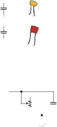
(1) Capacitor – 0.1 µF shown in Figure 5-10
(1)Capacitor – 0.01 µF, also shown in Figure 5-10
(2)Jumper wires
These capacitors do not have + and – terminals. You can safely connect these capacitors to a circuit without worrying about positive and negative terminals.
Page 150 · What’s a Microcontroller?
0.1 µF
0.01 µF
104
1 |
0 |
|
3 |
Figure 5-10
Ceramic Capacitors
The 0.1 F capacitor (above) and the 0.01 F capacitor (below) are both non-polar. You will not have to worry about positive and negative leads with these two parts.
Building an RC Time Circuit for the BASIC Stamp
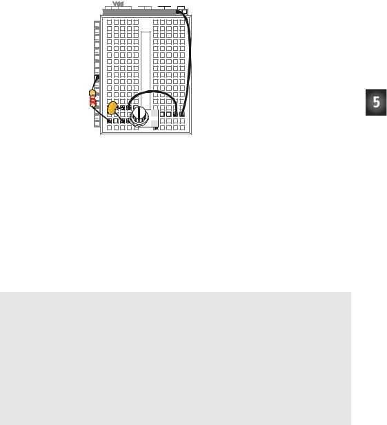
Figure 5-11 shows a schematic for the fast RC-time circuit, and Figure 5-12 shows the wiring diagram. This is the circuit that you will use to monitor the position of the potentiometer’s input shaft with the help of the BASIC Stamp and a PBASIC program.
√Build the circuit shown in Figure 5-11.
P7 


 220 Ω
220 Ω
nc
X
Pot |
0.1 µF |
Figure 5-11 |
||||||||
|
|
|
|
|
|
|
|
|
||
10 kΩ |
|
BASIC Stamp |
||||||||
|
|
|
|
|
|
|
|
|
|
|
|
|
|
|
|
|
|
|
|
|
RCTIME Circuit |
|
|
|
|
|
|
|
|
|
|
with Potentiometer |
|
|
|
|
|
|
|
|
|
|
|
|
|
|
|
|
|
|
|
|
|
|
|
|
|
|
|
|
|
|
|
|
|
|
|
|
|
|
|
|
|
|
|
|
Vss
Chapter #5: Measuring Rotation · Page 151
Vin Vss
X3


P15 |
P14 |
P13 |
P12 |
P11 |
P10 |
P9 |
P8 |
P7 |
P6 |
P5 |
P4 |
P3 |
P2 |
P1 |
P0 |
X2 |
Figure 5-12
Wiring Diagram for Figure 5-11
Programming RC-Time Measurements
The BASIC Stamp program to measure the potentiometer’s resistance will do essentially the same thing that you did by hand in Activity #2. The equivalent of pressing and holding the pushbutton is a HIGH command followed by a PAUSE. The RCTIME command is the BASIC Stamp module’s way of letting go of the pushbutton and polling until the capacitor’s voltage gets low enough to pass the threshold voltage of IN7 (1.4 V).
Example Program: ReadPotWithRcTime.bs2
√Enter and run ReadPotWithRcTime.bs2
√Try rotating the potentiometer’s input shaft while monitoring the value of the time variable using the Debug Terminal.
'What's a Microcontroller - ReadPotWithRcTime.bs2
'Read potentiometer in RC-time circuit using RCTIME command.
'{$STAMP BS2}
'{$PBASIC 2.5}
time VAR Word
DO
HIGH 7
PAUSE 100
RCTIME 7, 1, time
DEBUG HOME, "time = ", DEC5 time
LOOP
Page 152 · What’s a Microcontroller?
How ReadPotWithRcTime.bs2 Works
Here are the pseudo-code steps the program goes through to take the RC-time measurement.
•Declare the variable time to store a time measurement.
•Code block within DO…LOOP:
o Set I/O pin P7 to HIGH.
oWait for 100 ms (20 ms to make sure the capacitor is charged up and 80 more ms to keep the Debug Terminal display steady).
o Execute the RCTIME command.
o Store the time measurement in the time variable. o Display the value time in the Debug Terminal.
Before the RCTIME command is executed, the capacitor is fully charged. As soon as the RCTIME command executes, the BASIC Stamp changes the I/O pin from an output to an input. As an input, the I/O pin looks about the same to the circuit as when the pushbutton was released (open circuit) in Activity #2. The RCTIME command is a high speed version of the polling that was used in Activity #2, and it measures the amount of time it takes for the capacitor to lose its charge and fall below the I/O pin’s 1.4 V input threshold. Instead of counting in 100 ms increments, the RCTIME command counts in 2 s increments.
Your Turn – Changing Time by Changing the Capacitor
√Replace the 0.1 F capacitor with a 0.01 F capacitor.
√Try the same positions on the potentiometer that you did in the main activity and compare the value displayed in the Debug Terminal with the values obtained for the 0.1 F capacitor. Are the RCTIME measurements one tenth the value?
√Go back to the 0.1 F capacitor.
√With the 0.1 F capacitor back in the circuit and the 0.01 F capacitor removed, make a note of the highest and lowest values for the next activity.
ACTIVITY #4: CONTROLLING A SERVO WITH A POTENTIOMETER
Potentiometers together with servos can be used to make lots of fun things. This is the foundation for model airplanes, cars and boats. This activity shows how the BASIC Stamp can be used to monitor a potentiometer circuit and control the position of a servo.