

Basic for PIC Microcontrollers (M. Nebojsa, 2001)
.PDFBasic for PIC Microcontrollers |
31 |
Chapter 4
INSTRUCTIONS (1/4)
Introduction |
|
|
|
4.1 @ |
4.17 GOSUB |
4.33 LOOKUP2 |
4.49 RETURN |
4.2 ASM..ENDASM |
4.18 GOTO |
4.34 LOW |
4.50 REVERSE |
4.3 ADCIN |
4.19 HIGH |
4.35 NAP |
4.51 SELECT-CASE |
4.4 BRANCH |
4.20 HSERIN |
4.36 OUTPUT |
4.52 SERIN |
4.5 BRANCHL |
4.21 HPWM |
4.37 OWIN |
4.53 SERIN2 |
4.6 BUTTON |
4.22 HSEROUT |
4.38 OWOUT |
4.54 SEROUT |
4.7 CALL |
4.23 I2CREAD |
4.39 PAUSE |
4.55 SEROUT2 |
4.8 CLEAR |
4.24 I2CWRITE |
4.40 PAUSEUS |
4.56 SHIFTIN |
4.9 CLEARWDT |
4.25 INPUT |
4.41 POT |
4.57 SHIFTOUT |
4.10 COUNT |
4.26 IF-THEN-ELSE |
4.42 PULSIN |
4.58 SLEEP |
4.11 DATA |
4.27 LCDOUT |
4.43 PULSOUT |
4.59 SOUND |
4.12 DTMFOUT |
4.28 LCDIN |
4.44 PWM |
4.60 STOP |
4.13 EEPROM |
4.29 {LET} |
4.45 RANDOM |
4.61 SWAP |
4.14 END |
4.30 LOOKDOWN |
4.46 RCTIME |
4.62 TOGGLE |
4.15 FREQOUT |
4.31 LOOKDOWN2 |
4.47 READ |
4.63 WRITE |
4.16 FOR-NEXT |
4.32 LOOKUP |
4.48 READCODE |
4.64 WRITECODE |
|
|
|
4.65 WHILE-WEND |
Introduction
All the programs regardless of the fact how complicated or simple they may be are nothing else but a strict flow of the executions of instructions.
Instructions of branching are used in program for the decision-making (in which one of two or more program paths is being chosen). The basic instruction of branching in PIC BASIC language is instruction if. This instruction has several variations that furnish
necessary flexibility required for the realization of the logic of the decision-making (these variations comprise the use of term else and insertion of the instructions).
Instructions of repeating give the possibility of repeating one or more single instructions. The conducting expression determines how many times the repetition will be performed. The set of those instructions is composed of WHILE ... WEND and FOR ... NEXT.
Instructions of jump serve to change the flow of the program execution. The basic instruction of jump, GOTO, transfers the execution of the program to a signed instruction in a main program or inside subroutines. Other instructions of jump are BRANCH, BRANCHL, CALL, GOSUB, RETURN (these instructions are unavoidable in programs but their use is subject to certain restrictions).
Instructions of access to the peripheral devices facilitate the programmer's job. Now programmer can concentrate on the essence of the program he set out to solve, avoiding unnecessary waste of time in writing routine for LCD display or some other peripheral device he uses in his set. The set of instructions is such to satisfy the large part of needs in the design of even the most complicated microcontrollers systems.

Basic for PIC Microcontrollers |
32 |
4.1 @ Inserts one programming line of assembler code
Syntax: |
@ assembler's instruction |
|
|
|
|
||
Description |
If used at the beginning of the line @ enables free-style combining of the assemblers |
||
: |
code and PIC BASIC code. Instruction @ can be used for insertion of the libraries written |
||
|
in assembler as well. |
|
|
|
It should be taken notice that the further access from assembler towards variables works |
||
|
through the lower dash added to the variables name. In an example below, the variable |
||
|
B0 is used as_B0 in assembler programming line. |
||
|
|
|
|
Example: |
|
|
|
|
@include "some_asm_program.asm" |
' inserts an assembler code library |
|
|
B0 |
var byte |
|
|
Main : |
|
|
|
@ |
bsf _B0, 7 |
' sets the seventh bit of variable B0 |
|
Loop : goto Loop |
|
|
|
|
end |
|
|
|
|
|
4.2 ASM..ENDASM Inserts the block of assembler instructions
Syntax: ASM
/
assembler instructions
/
ENDASM
Description ASM and ENDASM instructions give the information that the code between ASM and
: ENDASM assembler type. Maximal size of the assembler code depends on the size of the programming memory of a microcontroller. In case of a PIC16F877 microcontroller the maximal value of an assembler code is 8K.
Example:
Basic for PIC Microcontrollers |
|
33 |
||
|
|
|
|
|
|
Main : |
|
|
|
|
asm |
|
' Beginning of asm part of the program |
|
|
bsf |
PORTA, 0 |
' |
set RA0 to "1" |
|
bcf |
PORTB, 3 |
' |
set RB3 to "0" |
|
endasm |
|
' End of asm part of the program |
|
|
Loop : goto Loop |
|
|
|
|
end |
|
|
|
|
|
|
|
|
4.3 ADCIN |
Write the values from the input of the internal AD converter |
||||
|
|
|
|
|
|
Syntax: |
|
ADCIN channel, variable |
|
|
|
|
|
|
|||
Description |
|
ADCIN performs A/D conversion of an input analogue signal in microcontrollers that have |
|||
: |
|
A/D converter built in chip (i.e. PIC16F877). The value read in is stored into a designated |
|||
|
|
variable. Before use of ADCIN instruction the appropriate TRIS register must be initiated |
|||
|
|
so that the given is designated input one. Beside that in ADCON1 register one has to set |
|||
|
|
the input pins for analogue working regime, format of the results and tact of A/D |
|||
|
|
converter. |
|
|
|
|
|
|
|
|
|
Example: |
|
|
|
|
|
|
|
DEFINE ADC_BITS 8 |
' |
|
Converted result will have 8, 10 or 12 bits |
|
|
DEFINE ADC_CLOCK 3 |
|
' |
Clock for A/D converter |
|
|
DEFINE ADC_SAMPLEUS 10 |
|
' |
Sampling time expressed in us |
|
|
B0 var byte |
|
|
|
|
|
Main : |
|
|
|
|
|
TRISA = $FF |
' |
All pins of port A are input |
|
|
|
ADCON1 = 0 |
' |
PORTA is analog |
|
|
|
|
|
|
|
Basic for PIC Microcontrollers |
34 |
|
|
|
|
|
adcin 0, B0 |
' Read the channel 0 and store the result into variable B0 |
|
Loop : goto Loop |
|
|
end |
|
|
|
|
4.4 BRANCH |
Jump onto label depending on given index |
||
|
|
||
Syntax: |
BRANCH index, [label1 {label...}] |
||
|
|
||
Description |
Depending on the specified index, jump is performed onto the corresponding label. For |
||
: |
instance if the index equals zero, execution continues from the first label indicated on the |
||
|
list on, and if it equals 1 from the second indicated one - and so on. In case that value of |
||
|
index is equal or even greater than the total number of labels, no action is undertaken |
||
|
and the execution of the program continues directly with the next instruction in a row. |
||
|
In the example below the same effect could be achieved with instruction if - then. |
||
|
if B0=0 then lab1 |
|
|
|
if B0=0 then lab1 |
|
|
|
if B0=0 then lab1 |
|
|
|
|
|
|
Example: |
|
|
|
|
B0 var byte |
|
|
|
Main : |
|
|
|
branch B0, [lab1, lab2, lab3] |
||
|
Loop : goto Main |
|
|
|
lab1 : |
' |
Labels where the program execution resumes after |
|
lab2 : |
' |
the jump initiated by instruction BRANCH |
|
lab3 : |
|
|
|
end |
|
|
|
|
|
|
4.5 BRANCHL Jump to the label in second code segment
Basic for PIC Microcontrollers |
|
35 |
|
|
|
|
|
Syntax: |
BRANCHL index, [ label1 {label...}] |
|
|
|
|
||
Description |
BRANCHL (BRANCH long) is a instruction quite similar to BRANCH. The only difference is |
||
: |
that BRANCHL can realize jump onto the location situated on the second code segment. |
||
|
BRANCHL instruction creates the code approximately two times greater than one created |
||
|
by BRANCH, so that in case that the whole code of a program is in one single code |
||
|
segment or occupies less then 2K of memory - use of BRANCH is recommended. |
||
|
|
|
|
Example: |
|
|
|
|
W0 var word |
|
|
|
Main : |
|
|
|
branchl |
W0, [lab1, lab2, lab3] |
|
|
Loop : goto Loop |
|
|
|
lab1 : |
' |
Labels where the program execution resumes after |
|
lab2 : |
' |
the jump initiated by instruction BRANCHL |
|
lab3 : |
|
|
|
end |
|
|
|
|
|
|
4.6 BUTTON |
Reads the state of button on input pin |
|
|
Syntax: |
BUTTON Pin, State, Delay, Speed, Variable, Action, Label |
|
|
Description |
The Button instruction eliminates the influence of contact flickering due to the pressing on |
: |
the button (debouncing), what could be interpreted by the program as the pressing of the |
|
button more then one time instead of only once. Beside this function, instruction Button |
|
secures the function of auto-repeat which enables execution of determinate instruction as |
|
long as we keep pressing the button. The time between consecutive execution of two |
|
instructions is specified with the argument Speed. |
|
Pin - Pin on which we have button. |
|
State - State of the pin when the button is pressed (0...1). |
|
Delay - Countdown time before we initiate auto-repeat (0...255). At value 0, there will be |
|
no auto-repeat. At value 255, the debouncing will be effectuated but without auto-repeat. |
|
Speed - Time of auto-repeat (0..255). |
|
|
Basic for PIC Microcontrollers |
36 |
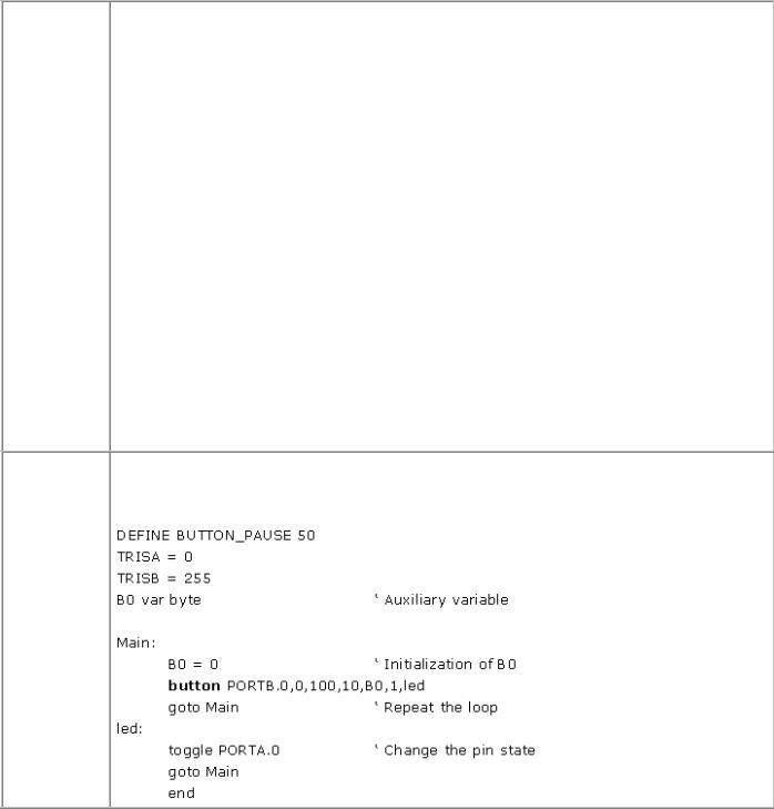
Variable - Auxiliary variable of byte type (which must be defined at the very beginning of program is used for delay and to repeat the countdown. Before any start of the button instruction it should be initiated on 0.
Action - State at which the jump onto the indicated label is to be effectuated (0 if the button is not pressed, 1 if it is). Simply put, if it is "0" it will jump if the button is not pressed, and if it is 1 it will jump if it is not pressed.
Label - The execution goes on from this label if the Action is correct.
button PORTB.1,0,100,10,B0,1,lab
If the button on pin is pressed, RB1 jumps on the label lab. Button is considered as a pressed on if there is a logical "0" on the RB1 pin.
button PORTB.1,0,100,10,B0,0,lab1
If the button on pin is not pressed, RB1 jumps on label lab1. Button is considered as a pressed on if there is a logical "0" on the RB1 pin.
button PORTB.1,1,100,10,B0,1,lab1
If the button on pin is pressed, RB1 jumps on label lab1. Button is pressed if there is a logical "1" on pin RB1.
Example: The example below will at each pressing of the button, which is connected to RA0, change the state of pin. If the diode is tied to the same pin the effect of the twinkling of the diode will be manifested.
4.7 CALL It calls assemblers subroutine
Basic for PIC Microcontrollers |
37 |
|
|
|
|
Syntax: |
CALL label |
|
|
|
|
Description |
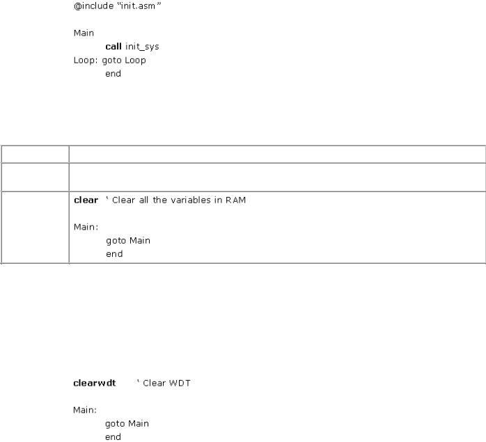
It executes the subprogram under the name Label in the language of assembler. |
|
: |
|
|
|
|
|
Example: |
|
|
|
|
|
4.8 CLEAR Sets the value of every variable to 0
Syntax: CLEAR
Description CLEAR sets the entire RAM registers in all databanks to zero. It also means that all the : variables will simultaneously be set to zero.
Example:
4.9 CLEARWDT Resets the watchdog timer
Syntax: |
CLEARWDT |
|
|
Description |
Resets the watchdog timer |
: |
|
|
|
Example: |
|
|
|
4.10 COUNT |
Counts the impulses on input pin |
|
|
Syntax: |
COUNT Pin, Period, No_Impulses |
|
|
Basic for PIC Microcontrollers |
38 |
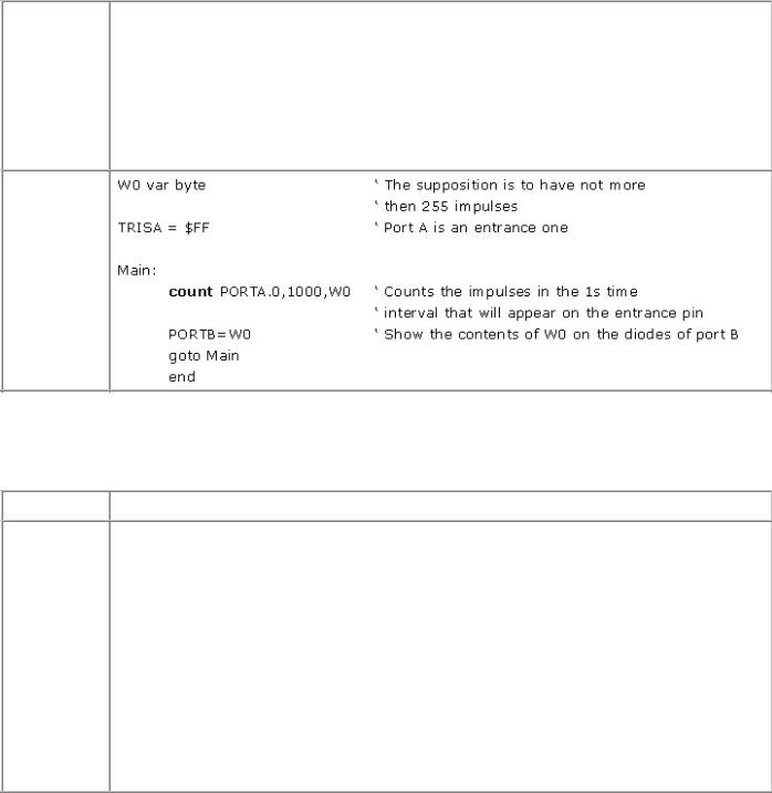
Description Counts the impulses that appear on a specified pin during the time interval defined with : the Period variable. The number of the impulses is stored into the No_Inpulse variable.
Pin is automatically designated as input. Period is specified in milliseconds. If the oscillator is a 4Mhz one, check of a pin state (status) is effectuated every 20 microseconds.
In this way, we can easily measure the frequency of a signal simply by determining number of it's impulses in one second (1000ms). Highest frequency measurable with 4MHz oscillator is 25kHz, while 20MHz oscillator measures up to 125kHz.
Example:
4.11 DATA Effectuates writing into the EEPROM at the first programming
Syntax: |
{label} DATA {@pocadr}, constant, constant.. |
Description DATA stores constants into the internal EEPROM at the first writing of any microcontroller : code. If the initial address from which the storing begins, constants will be stored from
the EEPROM'S zeroth one. Constant may be numerical or character. If it is necessary to save the constant occupying two bytes an official word "word" must be put before that constant (in the adverse case, only the lower byte would be saved.) Instruction DATA is applicable only in those PIC microcontrollers such as PIC16F84 or 16F87X series, which possess the built-in EEPROM memory inside the chip. Apart from the internal EEPROM in PIC microcontrollers exists the option of connecting an additional external EEPROM through the 12C highway. Such mode of connecting in practice in the PIC microcontrollers that don't possess internal EEPROM memory of their own or when its size is inadequate. EEPROM memory has that good property that it doesn't change its value in case of a power shortage. Besides, the possibility of unwanted storing is reduced so that the EEPROM memory is often used to conserve some values of prime importance. For inwriting and reading of EEPROM memories during the operations of microcontroller, instructions WRITE and READ are used.
Basic for PIC Microcontrollers |
39 |
Example:
4.12 DTMFOUT Generates the tone-dialing signal on the output pin
Syntax: |
DTMFOUT Pin, {Onms, Offms,} {Ton{, Ton...}} |
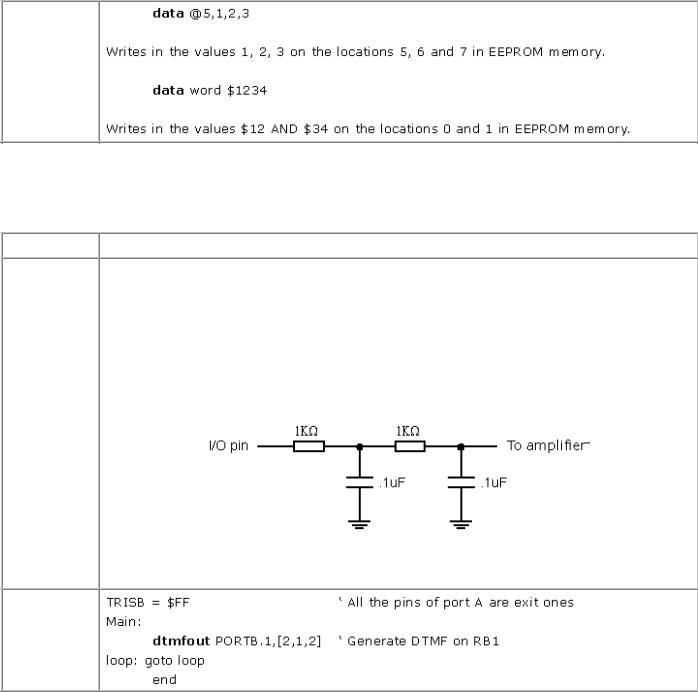
Description Instruction DTMFOUT produces the tone encountered for example in the phones with tone : dialing. Such characteristic tone is composed of two signals of different frequencies which
serves for the detection of the pressed button. Pin is thereby designated output. The parameter "Onms" represents the duration time of each dial in milliseconds, while "Offms" is the duration of the brake between two consecutive tones. If no value of duration of either tone or brake is set, it goes without saying that "Onms" lasts 200ms and "Offms" 50ms. Tones are numerated 0-15. Those 0-9 are identical to those on a phone dial. Tone 10 represents button * , tone 11 button #, while to the tones 12-15 correspond the additional buttons A-D.
In order to obtain the desired sinusoidal signal at the output, the installation of a sort of filter is required.
Example:
4.13 EEPROM Sets the initial contents for programming EEPROM
Syntax: |
EEPROM {@location, } constant {, constant} |
|
|
Description |
In sets constants into the consecutive bytes of the EEPROM memory. If the optional value |
|
|
Basic for PIC Microcontrollers |
40 |
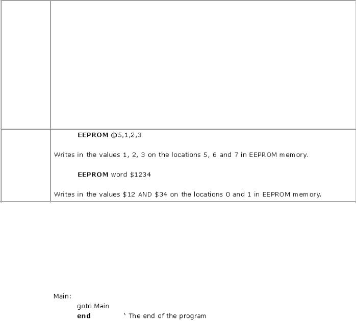
: of the location is omitted, the first EEPROM instruction starts to store the constants beginning with an address 0, and the next instructions place the values on the following locations. If the value of location is stipulated, the values are written starting from that very location.
Parameter "Constant" may be number or the sequence of constants. If "word" is not
quoted before constant that is being written in, only the bytes of lowest weights are saved. The sequences of are stored as consecutive bytes of ASCII values.
The instruction "EEPROM" is operative on only those PIC Microcontrollers, which possess EEPROM or FLASH programming memory built in the chip. The date are saved in the EEPROM space when the programming of microcontroller is definitely finished.
For inwriting and reading of EEPROM memory in the course of the operation of the microcontroller, the instructions WRITE and READ are being used.
Example:
4.14 END Marks the logical end of the program
Syntax: |
END |
|
|
Description |
Stops the further execution of the program and enters into the low energy consumption |
: |
mode executing continuous SLEEP instructions in a loop. Instruction END should be put at |
|
the end of every program. |
|
|
Example: |
|
|
|
4.15 FREQOUT Generates signal of a specified frequency on output pin
Syntax: |
FREQOUT Pin, Onms, Freq1, Freq2 |
|
|
Description |
FREQOUT generates the signals in the PWM form (Pulse Width Modulation) within the |
: |
frequency range from 0 to 32767Hz on the pin defined in parameter "Pin" and with the |
|
duration specified in parameter "Onms". |
|
|