

диафрагмированные волноводные фильтры / 5af5f68b-1793-48b2-bcdc-c106e3faa4d0
.pdfThis article has been accepted for inclusion in a future issue of this journal. Content is final as presented, with the exception of pagination.
IEEE TRANSACTIONS ON MICROWAVE THEORY AND TECHNIQUES |
1 |
An Integrated Ka-Band Diplexer-Antenna Array
Module Based on Gap Waveguide Technology
With Simple Mechanical Assembly and
No Electrical Contact Requirements
Abbas Vosoogh , Milad Sharifi Sorkherizi, Ashraf Uz Zaman, Member, IEEE,
Jian Yang , and Ahmed A. Kishk, Fellow, IEEE
Abstract— This paper presents the integration of a diplexer with a corporate feed network of a high gain slot array antenna at the Ka-band. A hybrid diplexer-splitter with a novel architecture is proposed to have compatibility for its direct integration with the feed network of the array antenna. A seventh-order hybrid diplexer-splitter is successfully integrated into a corporate feed network of a 16× 16 slot array antenna. The proposed integrated diplexer-antenna module consists of three distinct metal layers without the need of electrical contacts between the different layers based on the recently introduced gap waveguide technology. The designed module has two channels of 650-MHz bandwidths each with center frequencies 28.21 and 29.21 GHz. The fabricated prototype provides good radiation and input impedance characteristics. The measured input reflection coefficients for both Tx/Rx ports are better than −13 dB with the measured antenna efficiency better than 60% in the designed passband, which includes the losses in the diplexer.
Index Terms— Bandpass filter, diplexer, gap waveguide, group delay, high efficiency, integration, millimeter-wave, slot array antenna, space mapping.
I. INTRODUCTION
AHIGH gain antenna connected to a diplexer is one integral part of any frequency-division duplexing communication link that has a major influence on the performance of the complete system. The integration of these two components can significantly reduce the total size and cost of the system and improves the system functionality. There have been some attempts to integrate antennas and diplexers [1]–[3]. However, in these examples, the proposed single antenna element does not provide enough gain for high data rate point-to-point
Manuscript received June 30, 2017; accepted August 29, 2017. This work was supported in part by the Swedish Governmental Agency for Innovation Systems VINNOVA via a project within the VINN Excellence Center Chase and in part by the European Research Council under the 7th Framework Program ERC under Grant 321125. (Corresponding author: Abbas Vosoogh.)
A. Vosoogh, A. U. Zaman, and J. Yang are with the Department of Electrical Engineering, Chalmers University of Technology, 412 58 Gothenburg, Sweden (e-mail: abbas.vosoogh@chalmers.se; zaman@chalmers.se; jian.yang@chalmers.se).
M. S. Sorkherizi and A. A. Kishk are with the Electrical and Computer Engineering Department, Concordia University, Montreal, QC H3G 1M8, Canada (e-mail: mi_shari@encs.concordia.ca; kishk@encs.concordia.ca).
Color versions of one or more of the figures in this paper are available online at http://ieeexplore.ieee.org.
Digital Object Identifier 10.1109/TMTT.2017.2757469
wireless links, especially in the millimeter-wave frequency bands. Moreover, in all these cases, the diplexer is designed separately and connected to the antenna. Therefore, no major size reduction is observed in the total size of the module. The goal of this paper is to study the feasibility of integrating a practical diplexer into the feed network of a large-scale array antenna in a compact form. Therefore, the total size of the integrated module would be equal to that of the antenna.
Planar array antennas have several advantages over the reflector and lens antennas in terms of the size, assembly simplicity, and higher aperture efficiency. Therefore, they are preferred over the bulky lens and reflector antennas for many applications. Several works have been done to design highgain array antennas with improved efficiency. The microstrip and substrate integrated waveguide have been used for this objective [4]–[9]. However, their associated losses are a major limiting factor for applications at high frequencies, such as at Ka-band and higher. Hollow waveguides, on the other hand, have the superior performance in terms of efficiency. However, ensuring the electrical contact between the different metal parts is an expensive and complicated procedure that limits the application of waveguide-based high gain slot arrays especially at higher frequencies [10]. In order to achieve good electrical contact, diffusion bonding of thin copper plates is used in [11] and [12] to form corporate-feed hollow waveguide array antennas.
The gap waveguide technology that was proposed in [13] and [14] is an alternative to the conventional hollow waveguide to overcome the problem of the electrical contact between the different building blocks and still achieve low-loss performance, manufacturing flexibility, and cost effectiveness. Gap waveguide is based on parallel-plate waveguide configuration and using a semiperiodic array of electromagnetic bandgap structure to control the direction of propagation. By doing so, no electrical contact is required between the different metal blocks and metal layers. Several array antennas have been proposed in gap waveguide technology by using different fabrication techniques such as computer numerical control (CNC) machining [15], [16], die-sink electric discharge machining [17], direct metal laser sintering 3-D printing [18], and printed circuit board technology [19], [20].
0018-9480 © 2017 IEEE. Personal use is permitted, but republication/redistribution requires IEEE permission. See http://www.ieee.org/publications_standards/publications/rights/index.html for more information.

This article has been accepted for inclusion in a future issue of this journal. Content is final as presented, with the exception of pagination.
2 |
IEEE TRANSACTIONS ON MICROWAVE THEORY AND TECHNIQUES |
Design and optimization of diplexers is a topic that has been studied by many researchers for decades. Several geometries and methods have been proposed to calculate the lumped element model of the diplexers either by considering the impedance of the common port [21]–[28] or by optimization procedures [29], [30]. The major challenge is to translate the lumped element model to the physical dimensions of the structure since it involves numerical calculations of a computationally expensive structure due to its size. Generally, full-wave optimization and post fabrication tuning have major roles for this purpose. Bandpass filters are widely used to design diplexers [31], [32]. However, in some applications, where the relative bandwidth of the transmit and receive channels is large, it is better to use low-pass and high-pass filters combination instead of two bandpass filters [33].
The Q factors of the ridge and groove gap waveguide resonators has been investigated in [34] and compared with Q of a conventional rectangular waveguide. It has been shown that groove gap and rectangular waveguide have similar Q values. Using gap waveguide technology, several prototypes of filters have been proposed, tested, and shown the effectiveness of this technology to realize low-loss filters, especially at higher frequency bands [35]–[41]. In [42], the performance of a groove gap waveguide filter has been compared to the same filter made in conventional rectangular waveguide technology with comparable performance. It has been shown that the electrical contact between the sidewalls and the upper plate is not needed in gap waveguide technology and does not affect the performance. However, in hollow waveguide components, good electrical and galvanic contact between the building blocks is critical. In [43], the integration of waveguide filters into a corporate-fed slot array antenna at E-band is presented. The authors have used diffusion bonding of several laminated thin copper plates to form the waveguide structure and maintain good electrical contact between the layers, which is an expensive process.
For the purpose of this paper, it is required to integrate a power combiner/divider into a diplexer in order to implement it in the middle of the feed network of the array antenna in a way that each output port of the power combiner/divider excites each half of the feeding network equally. In [44], we presented a method to calculate the lumped element model of a hybrid diplexer-splitter using an efficient optimization routine. Here, the investigation is completed by providing more details on the design of the lumped model in Section III. Also, a method is proposed to translate the lumped model to physical dimensions efficiently without performing any full-wave optimization. In Section IV, the design of the 16 × 16 antenna array is presented. In Section V, the designed hybrid diplexer-splitter and the array antenna are integrated to propose an efficient and novel module for Ka-band. Finally, experimental validation of the designed integrated diplexer-antenna array module is presented in Section VI.
II. INTEGRATED DIPLEXER-ANTENNA
MODULE CONFIGURATION
The configuration of the proposed integrated diplexerantenna module is shown in Fig. 1. The array antenna consists
Fig. 1. (a) Configuration of the proposed integrated diplexer-antenna.
(b) Distribution feed network with an integrated diplexer.
of three distinct metal layers with a small gap between each layer. The PEC/PMC stopband produced by the pins suppresses the undesired parallel-plate modes and leakage. The radiating layer consists of 16 × 16 slots with element spacing slightly smaller than one wavelength. The slots are fed by cavities on the middle layer. Each cavity feeds four slots in the form of a subarray to enable corporate-fed excitation of slots, despite the limited space available to implement the feed network. In the lower layer, a ridge gap waveguide corporate feeding network is used to feed all the cavities via the coupling apertures.
The main element of the proposed module is a diplexer whose outputs are connected to a power combiner/divider. Fig. 1(b) shows the geometry of the distribution feed network with integrated hybrid diplexer-splitter in more detail. The diplexer consists of two seventh-order bandpass filters, whose

This article has been accepted for inclusion in a future issue of this journal. Content is final as presented, with the exception of pagination.
VOSOOGH et al.: INTEGRATED Ka-BAND DIPLEXER-ANTENNA ARRAY MODULE BASED ON GAP WAVEGUIDE TECHNOLOGY |
3 |
Fig. 2. Coupling diagram of a seventh-order channel hybrid diplexer-splitter [44].
Fig. 3. Hybrid diplexer-splitter using gap waveguide technology. (a) Top view without the upper lid. (b) 3-D view.
rectangular cavities and side walls are approximated by rows of pins. The designed hybrid diplexer-splitter is integrated into the feed network of the array antenna in the middle. Each output of the hybrid diplexer-splitter feeds each half of the feed network with the same phase and amplitude. A simple E-probe transition is designed to match the ridge gap waveguide to a standard WR-28 rectangular waveguide at the back of the antenna. The proposed module is a compact design with a simple mechanical assembly without any requirement of electrical contact between the building blocks.
III. HYBRID DIPLEXER-SPLITTER DESIGN
The first step of the design is to calculate the lumped element model or the coupling matrix (CM) of a hybrid diplexersplitter. To do so, we proposed a methodology in [44] that uses a modified goal function to calculate the CM of any integrated diplexer-power divider with Chebyshev responses. The coupling diagram of a hybrid seventh order channel diplexersplitter is shown in Fig. 2. The diplexer is composed of two channels with seven resonators intercoupled to each other. The diplexer also acts as a power divider at the output. A new error function is presented in [44] in order to eliminate a spurious resonance between Port 3 and Port 4 through Resonator 0. This has been done by applying a transmission zero in S43 at the center frequency of the diplexer. The objective is to have channels with center frequencies at 28.21 and 29.21 GHz with 650-MHz bandwidths.
The design procedure of the diplexer with CM in Fig. 2 is presented in [44]. In this section, realization of the CM model using the delay response of subcircuits is explained in more detail. Using the goal function in [44, eq (1)], the coupling values (k) and resonant frequencies ( f ) of the diagram of Fig. 2 are calculated and listed in Table I. For the output coupling of the diplexer (Ports 3 and 4 to Resonator 0), the normalized coupling of M = 1 is used as the initial value.
TABLE I
OPTIMIZED PARAMETERS OF THE LUMPED ELEMENT MODEL OF THE HYBRID DIPLEXER-SPLITTER (FIG. 2)
The normalization bandwidth is the total bandwidth of the diplexer (27.88–29.54 GHz). Furthermore, Resonator 0 is set to the center frequency of the diplexer.
The geometry of the realized CM is shown in Fig. 3. The structure consists of a semiperiodic array of metallic pins that together with the metal top plate create a bandgap to confine the energy inside the resonators without using any electrical contact between the lower part of the device and the top plate. Also, four guiding ridges are placed to work as the input–output of the device. Between each coupled cavity, a pair of extended pin controls the coupling. The value of the input–output couplings is controlled by the extension of the ridge into the resonators. The resonant frequency of the cavities is controlled by moving the semiperiodic pins away or close to each other. The dispersion diagram of the periodic metallic pin and the top plate unit cell is shown

This article has been accepted for inclusion in a future issue of this journal. Content is final as presented, with the exception of pagination.
4 |
|
|
|
|
|
|
|
|
|
|
|
IEEE TRANSACTIONS ON MICROWAVE THEORY AND TECHNIQUES |
|||||||||
|
|
|
|
|
|
|
|
|
|
|
|
|
|
|
|
|
|
|
|
|
|
|
|
|
|
|
|
|
|
|
|
|
|
|
|
|
|
|
|
|
|
|
|
|
|
|
|
|
|
|
|
|
|
|
|
|
|
|
|
|
|
|
|
|
|
|
|
|
|
|
|
|
|
|
|
|
|
|
|
|
|
|
|
|
|
|
|
|
|
|
|
|
|
|
|
|
|
|
|
|
|
|
|
|
|
|
|
|
|
|
|
|
|
|
|
|
|
|
|
|
|
|
|
|
|
|
|
|
|
|
|
|
|
|
|
|
|
|
|
|
|
|
|
|
|
|
|
|
|
|
|
|
|
|
|
|
|
|
|
|
|
|
|
|
|
|
|
|
|
|
|
|
|
|
|
|
|
|
|
|
|
|
|
|
|
|
|
|
|
|
|
|
|
|
|
|
|
|
|
|
|
|
|
|
|
|
|
|
|
|
|
|
|
|
|
|
|
|
|
|
|
|
|
|
|
|
|
|
|
|
|
|
|
|
|
|
|
|
|
|
|
Fig. 4. Dispersion diagram and the size of the infinite periodic pin unit cell (d f = 2.9 mm, a = 0.9 mm, g = 0.12 mm, and p = 1.76 mm).
Fig. 6. Simulated delay response of Subcircuit 1 after and before phase removal procedure.
Fig. 5. Subcircuit 1 of the hybrid diplexer-splitter.
in Fig. 4, calculated by the CST Eigenmode solver. It is seen that the bandgap covers our band of interest.
Due to the relatively complex structure of gap waveguide components, the simulation time is generally high. Therefore, an efficient and fast procedure is needed in order to realize the CM of the structure in Fig. 3. We used the delay response of the subcircuits and space mapping to calculate the cavity, iris, and ridge dimensions, without applying full-wave optimization. This method was introduced in [45] and [46] for bandpass filters and diplexers. We have adapted this method with some modification for the proposed hybrid diplexers-splitter. The structure is divided into three subcircuits. In each subcircuit, few resonators are considered in the circuit, and the rest are detuned by metallic pins in their centers. Therefore, their resonant frequency is shifted to a higher frequency, but their physical influence is still considered in the EM simulation. The group delay response of S11, S22, and S43 is used to calculate the CM parameters of each subcircuit individually. Afterward, the physical dimensions are calculated by using a linear mapping procedure. We used CST Microwave Studio for all simulations.
Fig. 5 shows Subcircuit 1 in which the structure is excited at Port 3, and Resonators 0, 5–7, and 8–10 are in the circuits while the rest of them are detuned using shorting pins. To calculate the accurate phase information, a transition from the ridge waveguide to the ridge gap waveguide is used in the subcircuit. This comes from the issues regarding defining a simulation port in CST for ridge gap waveguide. The effect of the transition will be removed by the procedure outlined in [45]. All the information about the resonant frequencies and couplings of the elements in Subcircuit 1 can be extracted from the group delay of S34. Fig. 6 shows the delay response
Fig. 7. Delay response of the optimized Subcircuit 1 and the CM.
Fig. 8. Subcircuit 2 of the hybrid diplexer-splitter.
of S34 of Subcircuit 1 after and before the phase removal procedure. As can be seen, this step is crucial to extract the correct couplings of the subcircuit.
By performing an iterative space mapping procedure, all the cavity sizes and the iris dimensions are extracted. Also, the length of input ridges from Port 3, and Port 4 that extrudes to Cavity 0 is calculated. This length reflects the value of output coupling (R0). The outcome of the optimization procedure is shown in Fig. 7 by presenting the compensated delay response of EM model and the response from the CM. The resonators at the end of channels (Resonator 5 and Resonator 10) are considered in the circuit in order to mimic the loading effect on their adjacent resonators, and their calculated dimensions will be disregarded later.
Subcircuit 2 is shown in Fig. 8, which includes Resonators 1 to 6 while the rest of resonators are detuned. Group delay of reflection from Port 1 after phase removal is

This article has been accepted for inclusion in a future issue of this journal. Content is final as presented, with the exception of pagination.
VOSOOGH et al.: INTEGRATED Ka-BAND DIPLEXER-ANTENNA ARRAY MODULE BASED ON GAP WAVEGUIDE TECHNOLOGY |
5 |
||||||||||||||||
|
|
|
|
|
|
|
|
|
|
|
|
|
|
|
|
|
|
|
|
|
|
|
|
|
|
|
|
|
|
|
|
|
|
|
|
|
|
|
|
|
|
|
|
|
|
|
|
|
|
|
|
|
|
|
|
|
|
|
|
|
|
|
|
|
|
|
|
|
|
|
|
|
|
|
|
|
|
|
|
|
|
|
|
|
|
|
|
|
|
|
|
|
|
|
|
|
|
|
|
|
|
|
|
|
|
|
|
|
|
|
|
|
|
|
|
|
|
|
|
|
|
|
|
|
|
|
|
|
|
|
|
|
|
|
|
|
|
|
|
|
|
|
|
|
|
|
|
|
|
|
|
|
|
|
|
|
|
|
|
|
|
|
|
|
|
|
|
|
|
|
|
|
|
|
|
|
|
|
|
|
|
|
|
|
|
|
|
|
|
|
|
|
|
|
|
|
|
|
|
|
|
|
|
|
|
|
|
|
|
|
|
|
|
|
|
|
|
|
|
|
|
|
|
|
|
|
|
|
|
|
|
|
|
|
|
|
|
|
|
|
|
|
|
|
|
|
|
|
|
|
|
|
|
|
|
|
|
|
|
|
|
|
|
|
|
|
|
|
|
|
|
|
|
|
|
|
|
|
|
|
|
|
|
|
|
|
|
|
|
|
|
|
|
|
|
|
|
|
|
|
|
|
|
|
|
Fig. 9. Delay response of the optimized Subcircuit 2 and the CM.
Fig. 12. Simulated EM response of the hybrid diplexer-splitter compared to CM.
Fig. 10. Subcircuit 3 of the hybrid diplexer-splitter.
Fig. 13. Simulated transmission of the hybrid diplexer-splitter compared to CM.
Fig. 11. Delay response of the optimized Subcircuit 3 and the CM.
used to optimize the subcircuit. By optimizing Subcircuit 2, dimensions of Resonators 1 to 5 and the iris dimensions incorporated with them will be calculated. It is important to note that Resonator 6 only exists in the circuit to mimic the loading effect on Resonator 5. The dimension for Resonator 6 calculated from Subcircuit 2 should be replaced by the value from Subcircuit 1. Also, the dimension calculated for Resonator 5 is the correct value and should replace the value calculated from Subcircuit 1. The outcome of the optimization of Subcircuit 2 is shown in Fig. 9.
In a similar way, Subcircuit 3 is generated as shown in Fig. 10. Resonators 9 to 14 are included in Subcircuit 3. After performing the phase removal procedure and an iterative space mapping process, all the dimensions of the Subcircuit 3 are calculated. The delay response of reflection from Port 2 for the optimized subcircuits along with the expected response from the CM is plotted in Fig. 11, which shows the very close behavior. The dimension calculated for Resonator 10 is the correct value and should replace the value calculated from Subcircuit 1. If the outlined procedure is performed correctly,
the iris dimension between Resonators 9 and 10 (responsible for coupling k10) that is calculated from Subcircuit 1 and also from Subcircuit 3 should be equal or very close. This also applies to the iris between Resonators 5 and 6 (k5) that is calculated from Subcircuits 1 and 2.
At this step, all the resonator widths, iris dimensions, and input–output lines are calculated based on the coupling diagram in Fig. 2. After removing all the shorting rods, the response of the entire hybrid diplexer-splitter can be calculated. The optimized response of the design is shown in Fig. 12. The full-wave simulated results show an excellent agreement with the designed CM model. The focused transmission response is provided in Fig. 13. Ideally, at each output of the power divider, magnitude of |S31|, |S41|, |S32|, and |S42| should be −3 dB since the power is divided equally. However, due to the finite conductivity of the materials, a certain amount of loss is observed. Using aluminum as the constructing material, a minimum of 0.9-dB insertion loss is noted at the outputs of both channels.
IV. ARRAY ANTENNA DESIGN
Fig. 14 shows the configuration of 2 × 2 cavity-backed slot subarray, as the radiating element of the array antenna. Four slots with cylindrical cavities on the top of them are

This article has been accepted for inclusion in a future issue of this journal. Content is final as presented, with the exception of pagination.
6 |
|
|
|
|
|
IEEE TRANSACTIONS ON MICROWAVE THEORY AND TECHNIQUES |
||||||||||
|
|
|
|
|
|
|
|
|
|
|
|
|
|
|
|
|
|
|
|
|
|
|
|
|
|
|
|
|
|
|
|
|
|
|
|
|
|
|
|
|
|
|
|
|
|
|
|
|
|
|
|
|
|
|
|
|
|
|
|
|
|
|
|
|
|
|
|
|
|
|
|
|
|
|
|
|
|
|
|
|
|
|
|
|
|
|
|
|
|
|
|
|
|
|
|
|
|
|
|
|
|
|
|
|
|
|
|
|
|
|
|
|
|
|
|
|
|
|
|
|
|
|
|
|
|
|
|
|
|
|
|
|
|
|
|
|
|
|
|
|
|
|
|
|
|
|
|
|
|
|
|
|
|
|
|
|
|
|
|
|
|
|
|
|
|
|
|
|
|
|
|
|
|
|
|
|
|
|
|
|
|
|
|
|
|
|
|
|
|
|
|
|
|
|
|
|
|
|
|
|
|
|
|
|
|
|
|
|
|
|
|
|
|
|
|
|
|
|
|
|
|
|
|
|
|
|
|
|
|
|
|
|
|
|
|
|
|
Fig. 14. Exploded view of 2 × 2 cavity-backed slot subarray.
Fig. 16. Simulated reflected coefficient of the subarray, ridge gap waveguide feed network, and complete 16 × 16 slot array.
TABLE II
DIMENSIONS OF 2 × 2 CAVITY-BACKED
SLOT SUBARRAY (FIGS. 14 AND 15)
Fig. 15. Bottom feeding layer geometry. (a) Perspective view. (b) Top view.
fed by an air-filled cavity, which is formed by the pins on the middle layer. The radiating element, i.e., slot layer and cavity layer are similar to the one in [47]. The slots are tilted by 10° as explained in [47] in order to improve the far-field radiation characteristics of the antenna and satisfy the European Telecommunications Standards Institute (ETSI) class II sidelobe requirement. By this means, the sidelobe levels of the antenna are reduced by separating the E- and H-planes of the antenna from the principal planes of the array.
In this paper, a new feed network with a novel feeding mechanism is proposed for corporate-fed excitation of the cavities. In [47] T-shaped ridges are used to couple the quasiTEM mode of the feed ridge lines to the cavities via coupling slots. There is only one pin row separation between the ridge lines near the T-shaped ridges in the feed network in [47]. Therefore, there is not enough space to place a diplexer in the middle of the feed network for a compact integration.
Fig. 15 shows the feeding layer of the proposed subarray. The quasi-TEM mode of the ridge line is first coupled to a secondary cavity and then to the subarray via a coupling slot. With this new excitation, there are at least two pin rows between the ridge lines and consequently adequate space to integrate diplexer into the distributing feeding network of the array.
The proposed subarray is optimized using CST Microwave Studio in infinite array environment with periodic boundary conditions. The simulated input reflection coefficient of the
subarray is shown in Fig. 16. The final dimensions of the subarray are also presented in Table II. A full corporate feed network is designed by cascading E-plane ridge gap waveguide T-junctions with equal power division. The design procedure of the feed network is similar to the one in [47]. The reflection coefficient of an 8×8 ways distribution network is also shown in Fig. 16. The output ports of the distributing network are terminated with waveguide ports in this figure. Furthermore, the simulated input reflection coefficient of the complete 16 × 16 slot array antenna is also presented in Fig. 16.

This article has been accepted for inclusion in a future issue of this journal. Content is final as presented, with the exception of pagination.
VOSOOGH et al.: INTEGRATED Ka-BAND DIPLEXER-ANTENNA ARRAY MODULE BASED ON GAP WAVEGUIDE TECHNOLOGY |
7 |
|||||||||||||
|
|
|
|
|
|
|
|
|
|
|
|
|
|
|
|
|
|
|
|
|
|
|
|
|
|
|
|
|
|
|
|
|
|
|
|
|
|
|
|
|
|
|
|
|
|
|
|
|
|
|
|
|
|
|
|
|
|
|
|
|
|
|
|
|
|
|
|
|
|
|
|
|
|
|
|
|
|
|
|
|
|
|
|
|
|
|
|
|
|
|
|
|
|
|
|
|
|
|
|
|
|
|
|
|
|
|
|
|
|
|
|
|
|
|
|
|
|
|
|
|
|
|
|
|
|
|
|
|
|
|
|
|
|
|
|
|
|
|
|
|
|
|
|
|
|
|
|
|
|
Fig. 17. Geometry of the rectangular waveguide to ridge gap waveguide transition (w p = 0.78 mm and l p = 2 mm).
Fig. 18. Simulated performances of the rectangular waveguide to ridge gap waveguide transition.
The response of the feed network and full array are calculated using full wave simulations. The reflection coefficient of the whole array is below −20 dB in the desired frequency band (over 27.9–29.9 GHz).
Fig. 17 shows the geometry of a simple E-probe rectangular waveguide to ridge gap waveguide transition which is designed to match the ridge gap waveguide line to the standard WR-28 rectangular waveguide. To have an easier connection between the inputs of the antenna and the measurement equipment, the WR-28 opening is also rotated 10° to be parallel to the radiating slots. The simulated S-parameters of the transition are shown in Fig. 18. The S11 is below −20 dB over the frequency band 27.5–31 GHz and the simulated insertion loss is smaller than 0.06 dB with aluminum as material over the same frequency band.
V. INTEGRATION OF DIPLEXER AND
THE ARRAY ANTENNA
The designed hybrid diplexer-splitter is integrated into the distribution feed network of the array antenna. Fig. 1(b) shows the feed network of the antenna with the integrated diplexer. The outputs of the hybrid diplexer-splitter are connected to the feed network at the middle of the antenna to act as the first power division stage. Therefore, the proposed architecture is
Fig. 19. Simulated E-field distribution within the feed network.
(a) 28.2 and (b) 29.2 GHz.
very compact. The inputs of the diplexer are connected to WR-28 rectangular waveguides in the bottom plate via simple transitions.
The simulated time-averaged amplitudes of the E-field distribution within the feed network of the antenna at the center frequencies of two Tx/Rx channels are illustrated in Fig. 19. As shown, despite the presence of a small gap between the layers and no electrical contact, there is no leakage between the feeding ridge lines and also between the diplexer and adjacent ridge lines. The latter is due to the stopband of the pin texture, which prevents the propagation of the wave in the unwanted directions.
To investigate any possible leakage in the feed network, the coupling between two parallel ridge lines with a different row of pins separation is studied. Coupling between Port 1 and Port 4 for two lines with a length of 30 mm is demonstrated in Fig. 20. The coupling increases by placing the

This article has been accepted for inclusion in a future issue of this journal. Content is final as presented, with the exception of pagination.
8 |
|
|
|
|
|
|
|
|
|
|
IEEE TRANSACTIONS ON MICROWAVE THEORY AND TECHNIQUES |
||||||||||
|
|
|
|
|
|
|
|
|
|
|
|
|
|
|
|
|
|
|
|
|
|
|
|
|
|
|
|
|
|
|
|
|
|
|
|
|
|
|
|
|
|
|
|
|
|
|
|
|
|
|
|
|
|
|
|
|
|
|
|
|
|
|
|
|
|
|
|
|
|
|
|
|
|
|
|
|
|
|
|
|
|
|
|
|
|
|
|
|
|
|
|
|
|
|
|
|
|
|
|
|
|
|
|
|
|
|
|
|
|
|
|
|
|
|
|
|
|
|
|
|
|
|
|
|
|
|
|
|
|
|
|
|
|
|
|
|
|
|
|
|
|
|
|
|
|
|
|
|
|
|
|
|
|
|
|
|
|
|
|
|
|
|
|
|
|
|
|
|
|
|
|
|
|
|
|
|
|
|
|
|
|
|
|
|
|
|
|
|
|
|
|
|
|
|
|
|
|
|
|
|
|
|
|
|
|
|
|
|
|
|
|
|
|
|
|
|
|
|
|
|
|
|
|
|
|
|
|
|
|
|
|
|
|
|
|
|
|
|
|
|
|
|
|
|
|
|
|
|
|
|
|
|
|
|
|
|
|
|
|
|
|
|
|
|
|
|
|
|
|
|
|
|
|
|
|
|
|
|
|
|
|
|
|
|
|
|
|
|
|
|
|
|
|
|
|
|
|
|
|
|
|
|
|
|
|
|
|
|
|
|
|
|
|
|
|
|
|
|
|
|
|
|
|
|
|
|
|
|
|
|
|
|
|
|
|
|
|
|
|
|
|
|
|
|
|
|
|
|
|
|
|
|
|
|
|
|
|
|
|
|
|
|
|
|
|
|
|
|
|
|
|
|
|
|
|
|
|
|
|
|
|
|
|
|
|
|
|
|
|
|
|
|
|
|
|
|
|
|
|
|
|
|
|
|
|
|
|
|
|
|
|
|
|
|
|
|
|
|
|
|
|
|
|
|
|
|
|
|
|
|
|
|
|
|
|
|
|
|
|
|
|
|
|
|
|
|
|
|
|
|
|
|
|
|
|
|
|
|
|
|
|
|
|
|
|
|
|
|
|
|
|
|
|
|
|
|
|
|
|
|
|
|
|
|
|
|
|
|
|
|
|
|
|
|
|
|
|
|
|
|
|
|
|
|
|
Fig. 20. Coupling between two parallel ridge lines separated by pin rows. |
Fig. 22. Comparison of simulated and measured input reflection coefficients. |
|||||||
|
|
|
|
|
|
|
|
|
|
|
|
|
|
|
|
|
|
|
|
|
|
|
|
|
|
|
|
|
|
|
|
|
|
|
|
|
|
|
|
|
|
|
|
|
Fig. 23. Measured isolation between input ports.
Fig. 21. Photograph of the fabricated integrated diplexer-antenna array module.
ridge lines closer with fewer rows of pins separation. In the designed feeding network with an integrated diplexer, there are minimum two rows of pins between the ridge lines. The coupling between two parallel ridge lines is lower than −37 dB for two rows of pins separation and −50 dB for three rows of pins separation. Therefore, coupling and leakage is not an issue in the designed gap waveguide feed network.
A prototype consisting of 16 × 16 slots has been manufactured by CNC milling. The fabricated integrated diplexerantenna module is illustrated in Fig. 21. The fabricated antenna has a planar structure with an aperture size of 180 × 180 mm2 and the total thickness of 10 mm.
VI. EXPERIMENTAL RESULTS
The measured and simulated input reflection characteristics of the manufactured module are presented in Fig. 22. There is a very good agreement between simulated and measured results. The measured reflection coefficients of the two Tx/Rx ports of the integrated diplexer-antenna module are below −13 dB. There is almost no shift in frequency between the simulated and measured input reflection coefficients. The measured
reflection coefficients are slightly higher than the simulated ones, which could be due to manufacturing and assembly tolerances. The measured isolation between two input ports is also illustrated in Fig. 23, which shows that there is no direct leakage between the two ports through the pins in the feed network.
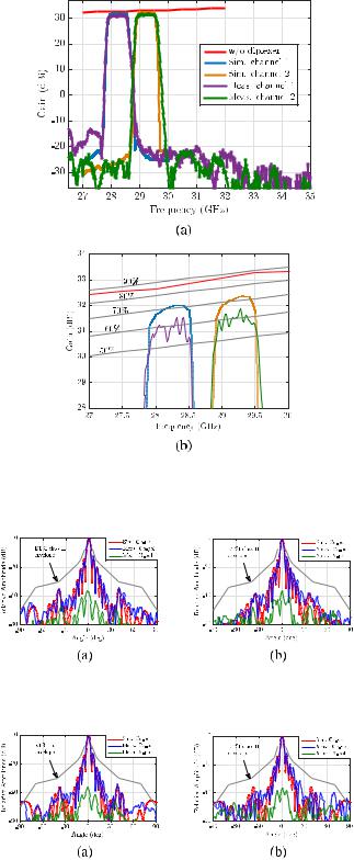
The simulated and measured gains of the fabricated module for two input ports are shown in Fig. 24. The simulated gain of the antenna without diplexer is also presented. The dashed lines in Fig. 24(b) correspond to the maximum available directivities for an aperture with the same size of the antenna with different aperture efficiencies. The simulated antenna efficiency without the diplexer is more than 85% over the frequency band 27–30 GHz. The gain of the antenna is decreased after integrating the diplexer into the feeding network of the antenna. This drop is due to the losses introduced by the diplexer. The simulated efficiency of the antenna with diplexer is around 70%. However, the measurements show lower gains and efficiencies. This reduction is attributed to the manufacturing tolerances and conductivity deterioration due to the surface roughness of the fabricated prototype. The simulated and measured gains of the two input ports of the proposed module are in good agreement with almost no shift in the operating frequency bands. The measured antenna efficiency of the fabricated integrated diplexer-antenna is around 60%.
The normalized simulated and measured E- and H-planes radiation patterns of the antenna at the center of the two channels of the diplexer 28.2 and 29.2 GHz are shown in Figs. 25 and 26, respectively. The designed antenna satisfies
This article has been accepted for inclusion in a future issue of this journal. Content is final as presented, with the exception of pagination.
VOSOOGH et al.: INTEGRATED Ka-BAND DIPLEXER-ANTENNA ARRAY MODULE BASED ON GAP WAVEGUIDE TECHNOLOGY |
9 |
Fig. 24. Measured and computed gains of the designed integrated diplexerantenna module. (a) Overview. (b) Details in the channels. The dashed lines are the directivities with 90%, 80%, 70%, and 60% aperture efficiencies.
Fig. 25. Simulated and measured radiation patterns of the proposed array antenna at 28.2 GHz. (a) E-plane. (b) H-plane.
Fig. 26. Simulated and measured radiation patterns of the proposed array antenna at 29.2 GHz. (a) E-plane. (b) H-plane.
the ETSI class II Co-polar radiation pattern sidelobe requirement. The measured and simulated Co-polar radiation patterns are in good agreement, which shows that the hybrid diplexersplitter feeds the two halves of the array feeding network with the same amplitude and phase. The measured cross-polar
patterns are also presented in Figs. 25 and 26. The measured cross-polarization levels are better than −35 dB in the both E- and H-planes.
VII. CONCLUSION
The integration of a diplexer into a corporate feed network of a slot array antenna has been presented at the Ka-band. A compact integrated diplexer-antenna array has been designed using gap waveguide technology. The proposed module consists of three unconnected metal layers with simple mechanical assembly without the need of electrical contact between the metal blocks. This has been realized using the stopband property of the pin texture to prevent any possible leakage and by controlling the direction of the wave propagation in a parallel plate waveguide configuration. The detail design procedure of a new method for designing of large-scale filters and diplexers based on the group delay responses of subcircuits in combination with space mapping has been presented. The proposed hybrid diplexer-splitter has been optimized with the proposed method efficiently with few full-wave simulations.
A prototype consisting of 16 × 16 cavity-backed slots with integrated diplexer has been manufactured with CNC milling. The fabricated prototype showed high gain and high efficiency. The designed integrated diplexer-antenna array has two channels with center frequencies at 28.21 and 29.21 GHz with 650-MHz bandwidths, connected to standard WR-28 rectangular waveguides at the back side of the antenna. The measured input reflection coefficients of both Tx/Rx ports are better than −13 dB. The proposed antenna has very good radiation characteristics and satisfies the ETSI class II Co-polar sidelobe envelope requirement. The measured antenna efficiency is better than 60% in the designed passbands with high isolation of gain between two ports. The overall performance of the integrated diplexer-antenna module is quite promising, and this can open up new development of such integrated modules in the future.
ACKNOWLEDGMENT
This work had been done under the supervision of the late Prof. P.-S. Kildal. The authors would like to thank Prof. P.-S. Kildal, as he was a source of inspiration to the members of the Antenna Group, Chalmers University of Technology, Gothenburg, Sweden. His absence will always be felt, and the work started by him on gap waveguide technology will be continued.
REFERENCES
[1]T.-Y. Yun et al., “A 10to 21-GHz, low-cost, multifrequency, and fullduplex phased-array antenna system,” IEEE Trans. Antennas Propag., vol. 50, no. 5, pp. 641–650, May 2002.
[2]C. S. Cabello and E. Rajo-Iglesias, “Low cost self-diplexed antenna in inverted microstrip gap waveguide technology,” in Proc. Int. Symp. Antennas Propag. (ISAP), Dec. 2014, pp. 169–170.
[3]Z. Kordiboroujeni, L. Locke, and J. Bornemann, “A diplexing antenna system in substrate integrated waveguide technology,” in Proc. IEEE Int. Symp. Antennas Propag. USNC/URSI Nat. Radio Sci. Meeting, Jul. 2015, pp. 1042–1043.
This article has been accepted for inclusion in a future issue of this journal. Content is final as presented, with the exception of pagination.
10
[4]J. Wu, Y. J. Cheng, and Y. Fan, “A wideband high-gain high-efficiency hybrid integrated plate array antenna for V-band inter-satellite links,” IEEE Trans. Antennas Propag., vol. 63, no. 4, pp. 1225–1233, Apr. 2015.
[5]Y. J. Cheng, Y. X. Guo, and Z. G. Liu, “W-band large-scale high-gain planar integrated antenna array,” IEEE Trans. Antennas Propag., vol. 62, no. 6, pp. 3370–3373, Jun. 2014.
[6]W. C. Yang, H. Wang, W. Q. Che, Y. Huang, and J. Wang, “Highgain and low-loss millimeter-wave LTCC antenna array using artificial magnetic conductor structure,” IEEE Trans. Antennas Propag., vol. 63, no. 1, pp. 390–395, Jan. 2015.
[7]S. B. Yeap, Z. N. Chen, and X. Qing, “Gain-enhanced 60-GHz LTCC antenna array with open air cavities,” IEEE Trans. Antennas Propag., vol. 59, no. 9, pp. 3470–3473, Sep. 2011.
[8]J. Xu, Z. N. Chen, X. Qing, and W. Hong, “Bandwidth enhancement for a 60 GHz substrate integrated waveguide fed cavity array antenna on LTCC,” IEEE Trans. Antennas Propag., vol. 59, no. 3, pp. 826–832, Mar. 2011.
[9]Y. Li and K. M. Luk, “60-GHz substrate integrated waveguide fed cavitybacked aperture-coupled microstrip patch antenna arrays,” IEEE Trans. Antennas Propag., vol. 63, no. 3, pp. 1075–1085, Mar. 2015.
[10]Y. Miura, J. Hirokawa, M. Ando, Y. Shibuya, and G. Yoshida, “Doublelayer full-corporate-feed hollow-waveguide slot array antenna in the
60-GHz band,” IEEE Trans. Antennas Propag., vol. 59, no. 8,
pp. 2844–2851, Aug. 2011.
[11]K. Hashimoto, J. Takeuchi, J. Hirokawa, A. Hirata, and M. Ando,
“Design and fabrication of a dual-polarization corporate-feed waveguide 32 × 32-slot array antenna for 120 GHz band,” in Proc. Int. Symp. Antennas Propag. (ISAP), Dec. 2014, pp. 33–34.
[12] |
Y. Miura, J. Hirokawa, M. Ando, K. Igarashi, |
and |
G. Yoshida, |
|
“A circularly-polarized aperture array antenna with a corporate-feed |
||
|
hollow-waveguide circuit in the 60 GHz-band,” in Proc. IEEE Int. Symp. |
||
|
Antennas Propag. (APSURSI), Jul. 2011, pp. 3029–3032. |
|
|
[13] |
P.-S. Kildal, “Artificially soft and hard surfaces |
in electromagnet- |
|
|
ics,” IEEE Trans. Antennas Propag., vol. 38, no. 10, pp. 1537–1544, |
||
|
Oct. 1990. |
|
|
[14] |
P.-S. Kildal, A. U. Zaman, E. Rajo-Iglesias, |
E. |
Alfonso, and |
A. Valero-Nogueira, “Design and experimental verification of ridge gap waveguide in bed of nails for parallel-plate mode suppression,” IET Microw., Antennas Propag., vol. 5, no. 3, pp. 262–270, Feb. 2011.
[15]A. Vosoogh and P.-S. Kildal, “Corporate-fed planar 60-GHz slot array made of three unconnected metal layers using AMC pin surface for the gap waveguide,” IEEE Antennas Wireless Propag. Lett., vol. 15,
pp.1935–1938, Dec. 2015.
[16]A. U. Zaman and P.-S. Kildal, “Wide-band slot antenna arrays with single-layer corporate-feed network in ridge gap waveguide technology,” IEEE Trans. Antennas Propag., vol. 62, no. 6, pp. 2992–3001, Jun. 2014.
[17]A. Vosoogh, P.-S. Kildal, and V. Vassilev, “A multi-layer gap waveguide array antenna suitable for manufactured by die-sink EDM,” in Proc. 10th Eur. Conf. Antennas Propag. (EuCAP), 2016, pp. 1–4.
[18]A. Vosoogh, P.-S. Kildal, V. Vassilev, A. U. Zaman, and S. Carlsson, “E-band 3-D metal printed wideband planar horn array antenna,” in Proc. Int. Symp. Antennas Propag. (ISAP), 2016, pp. 304–305.
[19]S. A. Razavi, P.-S. Kildal, L. Xiang, E. Alfonso Alos, and H. Chen, “2 × 2-slot element for 60-GHz planar array antenna realized on two doubled-sided PCBs using SIW cavity and EBG-type soft surface fed by microstrip-ridge gap waveguide,” IEEE Trans. Antennas Propag., vol. 62, no. 9, pp. 4564–4573, Sep. 2014.
[20]H. Attia, M. S. Sorkherizi, and A. A. Kishk, “60 GHz slot antenna array based on ridge gap waveguide technology enhanced with dielectric superstrate,” in Proc. 9th Eur. Conf. Antennas Propag. (EuCAP), 2015,
pp.1–4.
[21]F. M. Vanin, D. Schmitt, and R. Levy, “Dimensional synthesis for wideband waveguide filters and diplexers,” IEEE Trans. Microw. Theory Techn., vol. 52, no. 11, pp. 2488–2495, Nov. 2004.
[22]A. Garcia-Lamperez, M. Salazar-Palma, and T. K. Sarkar, “Analytical synthesis of microwave multiport networks,” in IEEE MTT-S Int. Microw. Symp. Dig., vol. 2. Jun. 2004, pp. 455–458.
[23]A. Morini, T. Rozzi, and M. Morelli, “New formulae for the initial design in the optimization of T-junction manifold multiplexers,” in IEEE MTT-S Int. Microw. Symp. Dig., vol. 2. Jun. 1997, pp. 1025–1028.
[24]J. Rhodes and R. Levy, “A generalized multiplexer theory,” IEEE Trans. Microw. Theory Techn., vol. MTT-27, no. 2, pp. 99–111, Feb. 1979.
[25]K. L. Wu and W. Meng, “A direct synthesis approach for microwave filters with a complex load and its application to direct diplexer design,”
IEEE Trans. Microw. Theory Techn., vol. 55, no. 5, pp. 1010–1017, May 2007.
IEEE TRANSACTIONS ON MICROWAVE THEORY AND TECHNIQUES
[26]H. Meng and K.-L. Wu, “Direct optimal synthesis of a microwave bandpass filter with general loading effect,” IEEE Trans. Microw. Theory Techn., vol. 61, no. 7, pp. 2566–2573, Jul. 2013.
[27]G. Macchiarella and S. Tamiazzo, “Generation of canonical forms for multiport filtering networks,” in IEEE MTT-S Int. Microw. Symp. Dig., Jun. 2014, pp. 1–3.
[28]U. Rosenberg and S. Amari, “New power distribution (combination) method with frequency selective properties,” in Proc. Eur. Microw. Conf., 2012, pp. 1–34.
[29]P. Zhao and K. L. Wu, “An iterative and analytical approach to optimal synthesis of a multiplexer with a star-junction,” IEEE Trans. Microw. Theory Techn., vol. 62, no. 12, pp. 3362–3369, Dec. 2014.
[30]S. Amari, “Synthesis of cross-coupled resonator filters using an analytical gradient-based optimization technique,” IEEE Trans. Microw. Theory Techn., vol. 48, no. 9, pp. 1559–1564, Sep. 2000.
[31]E. Ofli, R. Vahldieck, and S. Amari, “Novel E-plane filters and diplexers with elliptic response for millimeter-wave applications,”
IEEE Trans. Microw. Theory Techn., vol. 53, no. 3, pp. 843–851, Mar. 2005.
[32]J. M. Rebollar, J. R. Montejo-Garai, and A. Ohoro, “Asymmetric H-plane T-junction for broadband diplexer applications,” in Proc. IEEE Antennas Propag. Soc. Int. Symp., vol. 4. Jul. 2000, pp. 2032–2035.
[33] |
F. Teberio, I. Arregui, P. Soto, M. A. Laso, V. |
E. Boria, and |
|
M. Guglielmi, “High-performance compact diplexers for Ku/K-band |
|
|
satellite applications,” IEEE Trans. Microw. Theory Techn., vol. 65, |
|
|
no. 10, pp. 3866–3876, Oct. 2017. |
|
[34] |
E. Pucci, A. U. Zaman, E. Rajo-Iglesias, P.-S. Kildal, |
and A. Kishk, |
|
“Study of Q-factors of ridge and groove gap waveguide resonators,” |
|
|
IET Microw., Antennas Propag., vol. 7, no. 11, |
pp. 900–908, |
|
Aug. 2013. |
|
[35]E. A. Alös, A. U. Zaman, and P.-S. Kildal, “Ka-band gap waveguide coupled-resonator filter for radio link diplexer application,” IEEE Trans. Compon., Packag., Manuf. Technol., vol. 3, no. 5, pp. 870–879, May 2013.
[36]M. Rezaee, A. U. Zaman, and P.-S. Kildal, “V-band groove gap waveguide diplexer,” in Proc. 9th Eur. Conf. Antennas Propag. (EuCAP), May 2015, pp. 1–4.
[37]M. S. Sorkherizi, A. Khaleghi, and P.-S. Kildal, “Direct-coupled cavity filter in ridge gap waveguide,” IEEE Trans. Compon., Packag., Manuf. Technol., vol. 4, no. 3, pp. 490–495, Mar. 2014.
[38]M. Rezaee, A. U. Zaman, and P.-S. Kildal, “A groove gap waveguide iris filter for V-band application,” in Proc. 23rd Iranian Conf. Electr. Eng., 2015, pp. 462–465.
[39]M. S. Sorkherizi and A. A. Kishk, “Fully printed Gap waveguide with facilitated design properties,” IEEE Microw. Wireless Compon. Lett., vol. 26, no. 9, pp. 657–659, Sep. 2016.
[40]A. Vosoogh, A. A. Brazález, and P.-S. Kildal, “A V-band inverted microstrip gap waveguide end-coupled bandpass filter,” IEEE Microw.
Wireless Compon. Lett., vol. 26, no. 4, pp. 261–263, Apr. 2016.
[41] A. Berenguer, M. Baquero-Escudero, D. Sanchez-Escuderos, B. Bernardo-Clemente, and V. E. Boria-Esbert, “Low insertion loss 61 GHz narrow-band filter implemented with groove gap waveguides,” in Proc. 44th Eur. Microw. Conf. (EuMC), 2014, pp. 191–194.
[42]M. S. Sorkherizi and A. A. Kishk, “Completely tuned coupled cavity filters in defected bed of nails cavity,” IEEE Trans. Compon., Packag., Manuf. Technol., vol. 6, no. 12, pp. 1865–1872, Dec. 2016.
[43]X. Xu, M. Zhang, J. Hirokawa, and M. Ando, “E-band plate-
laminated waveguide filters and their integration into a corporatefeed slot array antenna with diffusion bonding technology,” IEEE Trans. Microw. Theory Techn., vol. 64, no. 11, pp. 3592–3603, Nov. 2016.
[44]M. S. Sorkherizi, A. Vosoogh, A. A. Kishk, and P.-S. Kildal, “Design of integrated diplexer-power divider,” in IEEE MTT-S Int. Microw. Symp. Dig., May 2016, pp. 1–3.
[45]M. S. Sorkherizi, A. A. Kishk, and M. Saad, “High rejection stacked bandpass filter optimized by group delay response,” in IEEE MTT-S Int. Microw. Symp. Dig., May 2015, pp. 1–4.
[46]M. S. Sorkherizi and A. A. Kishk, “Use of group delay of sub-circuits in optimization of wideband large-scale bandpass filters and diplexers,”
IEEE Trans. Microw. Theory Techn., vol. 65, no. 8, pp. 2893–2905, Aug. 2017.
[47]A. Vosoogh, P.-S. Kildal, and V. Vassilev, “Wideband and high-gain corporate-fed gap waveguide slot array antenna with ETSI class II radiation pattern in V-band,” IEEE Trans. Antennas Propag., vol. 65, no. 4, pp. 1823–1831, Apr. 2017.