

диафрагмированные волноводные фильтры / 2235ec6d-fcac-4646-a7e6-53fc47967ba0
.pdfProceedings of the 46th European Microwave Conference
Design of 3D Printed Plastic Modular Filters
Jérémy Saucourt, Nicolas Jolly, Aurélien Périgaud, Olivier Tantot, Nicolas Delhote, Stéphane Bila, Serge Verdeyme
XLIM UMR 7252, University of Limoges/CNRS
123 Avenue Albert Thomas, 87060, France
olivier.tantot@xlim.fr
Abstract—The design of 3D printed plastic modular filters is presented in this paper. The proposed principle allows the user to choose at will the order of a bandpass filter by plugging as much blocks (resonators) as needed. The conception and results of a 4- poles filter are discussed. Because of their simplicity, these filters have the potential to be used for microwave practical courses thanks to good performances, quick and easy assembly, easy tuning and maintenance and finally low cost manufacturing.
Keywords—Volumic filters, 3D printing technology, modular filter, quick and easy assembly.
I. INTRODUCTION
Previous studies have proved the efficiency of the plastic additive manufacturing [1] and metal manufacturing [2] for microwave applications when fast and low cost solutions are required.
In the first part of this paper, the initial concept of modular filter is presented, as well as improvement of the initial design. Then, the second part deals with HFSS simulations focused on losses coming from the joints between blocks and tuning screws.
After that HFSS simulations of bandpass filters made from elementary blocks are presented, describing filtering possibilities and performances of a modular waveguide filter.
Finally, measurements made from a 3D printed modular plastic filter are analyzed and confronted to simulations.
II. MODULAR FILTERS CONCEPT, PROBLEMS, AND SOLUTIONS
OF USE
A. Waveguide used and cavity tuning
The aim is to design and build a modular and tunable filter made of elementary blocks which are assembled. In order to validate the principle, a rectangular WR75 waveguide is used on the fundamental mode TE10 mode allowing to work in the 9 to 15 GHz range. Cavities are created in the waveguide by placing metal planes separated by a distance equal to g/2 in order to make incident and reflected waves interfere constructively [3].
Tuning the resonant frequency of a cavity is achieved by disturbing an established EM field, for instance by inserting a metal plane parallel to the E field in a position where the field is maximum [4]. Considering a TE101 mode cavity, a screw can be placed in the center of the cavity for that purpose.
When the screw depth in the cavity is increased, the resonant frequency decreases because of an additional capacitance created between the screw faces and the cavity walls. These additional capacitors, added to the capacitance of the RLC equivalent circuit of the cavity decreases its resonant frequency accordingly.
B. Screw joint problems and solutions
To be effective, the cavity tuning that is described above requires a metal insertion where the field is maximum. However, since the cavity-screw joint is collinear to the H field of the TE101 mode, which is the first resonant mode of the chosen cavity, part of the EM field leaks from the coaxial effect created by the screw in the cavity.
The tuning of the cavity frequency using a screw is a relatively simple method, compared to plungers or movable walls methods described in the literature [4], since it allows linear displacement. In order to limit the EM filed leakage problem, two improvements can be applied:
Dielectric screws instead of metal screws: even if the dielectric relative permittivity of the dielectric screws is low, resonant frequency tuning remains possible. The leakage coming from the screws is also limited because the dielectric screws inside the cavity holes are similar to a small cylindrical waveguide with a cutoff frequency way higher than the resonant frequency of the cavity. The radiated energy from this part of the device is therefore much more limited.
Optimised cavity thickness: If one consider metal screws and a cavity thickness equal to g/4, then a perfect E plane is presented on the cavity-screw joint in the cavity top wall. This principle may be applied for low permittivity dielectric screws as well.
III. HFSS SIMULATIONS OF CAVITY TUNING AND ASSOCIATED
LOSSES
A. Tuning screw and associated losses
The resonant modes and unloaded Q factors of the proposed cavity have been simulated for different screw diameters, lengths and materials. The cavity walls are considered plated with a silver paint ( = 5 s/μm) and is vacuum-filled. The screw is separated from the cavity wall by a 100 μm air gap.
978-2-87487-043-9 © 2016 EuMA |
369 |
4 –6 Oct 2016, London, UK |

In order to simulate losses from the air gap around the screw (in addition to metallic and dielectric losses), either a 377 impedance ring (for a metal screw) or a 377 impedance disk (for a Teflon screw) is placed on the external face of the cavity at the end of the screw (Fig. 1). This impedance surfaces limit reflected waves by simulating the transition to the air surrounding the cavity and thus takes into account the coaxial effect leakage (in the case of a metal screw), or circular waveguide leakage (in the case of a dielectric screw).
Fig. 1. Cavity tuning setups for a metal screw and a dielectric screw
Fig. 2. Frequency shift of the cavity
Considering different lengths of the screw in the cavity, the resulting frequency shift are presented in Fig 3. The screws have the purpose to adjust the central frequency and the bandwidth of the filter, and not to tune these parameters over a wide range. Thus, low relative permittivity dielectric screws (such as Teflon screws) are sufficient. The Q factor results presented in Fig. 4 show that less energy is leaking through dielectric screws. Long metal screws decreases the Q factor to nearly zero, which is normal with the decrease of the equivalent volume and the full perturbation of the resonant mode.
Even if the frequency shifting is less important with Teflon screws, the quality factor is much better. Dielectric screws are then a good compromise between frequency shifting and losses. If the aim is to adjust the filter over a 500 MHz frequency range for instance to compensate geometrical dimensions dispersion, dielectric screws are sufficient for that purpose.
Teflon screws have been simulated with relative permittivity equal to 2.1 and dielectric losses equal to 10-3 at 1 GHz.
Fig. 3. Q factor of the cavity
B. Elementary block losses
In order to evaluate the leakage coming through connected waveguide flanges, a 100 %m air gap has been considered. Different flange contact setups are compared (B rectangular flange, B+ rectangular flange with screw, C circular flange).
Fig. 4. Join set-up configurations
Setup B presents λg/4 wide flanges parallel to the inner waveguide. Setup B+ includes metal screws (2 mm diameter) on the flanges corners. Setup C use circular flange Simulations results of these 3 setups are provided in Fig. 5.
Fig. 5. S-parameters for join set-up configuration
Setup B+ shows the best overall performances: no spurious modes and correct insertion loss.
IV. COUPLING SYNTHESIS STUDY
We will now use such cavities in order to design bandpass filters. We will more particularly run simulations in order to study the effect of screws placed in the inductive iris between two cavities and their impact on the coupling coefficient [5, 6, 7]. A standard Chebyshev filter synthesis is then performed to calculate the external Q factor (Qe) and the coupling between adjacent resonators (k) with the following parameters: central frequency (12.0 GHz), equi-ripple Band-Width (200 MHz), ripple (0.2dB) for 2, 3 or 4 resonators. Simulations are realized with a fixed width of the iris for the calculations of the external Q factor (Qe) and the coupling factor (k). Only one
370

resonator is used with two input/output waveguides to calculate Qe as a function of the depth of the screw. The coupling factor k can be determined thanks to the simulation of two cavities with the variation of the depth of the screw inside the iris. Fig. 6 presents the obtained coupling laws for Teflon screws with 5 mm diameter. These values are then used to complete the filter theoretical synthesis.
A good accuracy is produced from the Polyjet technology with a maximum deviation from the nominal values as low as 60 μm.
Fig. 7. Manufactured elements
Fig. 6. Qe and k as a function of the screw length and for different screw diameters.
V. MANUFACTURING AND MEASUREMENT OF MODULAR
FILTERS
A. Manufacturing of modular filters and design errors
The idea is to obtain modular and simple elementary blocks that have to be assembled and aligned in order to create a bandpass filter. Thus no complicated or non-symmetrical locking methods are wanted here. The alignment and locking functions are then made in a way that they can be manipulated separately.
Alignment is the easiest function to make by placing on each connecting face pins and holes. However locking is critical in our case since a bad electrical connection lead to significant losses (see part III.b). Modular locking can be achieved by inserting locking keys in locking holes at each block connection (Fig. 9.b). First trials using the Polyjet 3D printer (Objet 260 Connex1 from Stratasys) andinvolving different pin and locking key sizes have been made. We seek here the dimensions which lead to the best possible connection between two blocks.
After this step, building blocks (input/output waveguides, resonators) designed to build multi-poles bandpass filters have been 3D printed (Fig. 7, Fig. 9.a, and 9.b). The I/O waveguides are made here with standard WR 75 dimensions. Each iris join contains a slot in order to improve the electrical connection. The main purpose of the locking key is to connect the adjacent blocks. It also presents a hole to let a screw going through it for the tuning of the coupling coefficient. Similar building blocks can be used for bandstop filters.
Post-manufacturing processes involves a 24h soda bath, drying and ethanol cleaning, in order to clean structural plastic defects and to obtain a sleek surface. Then, the WR75 transition blocks and the cavity blocks dimensions have been checked. Some manufacturing dispersion has been observed on the elements dimensions but remains low (Fig. 8).
Fig. 8. Dispersion of the 3D printed cavity dimensions
Screw holes are finally drilled and threaded so that M5 screws can be used. Then, each element faces interacting with the EM field are Silver painted three times (to increase the surface conductivity), until the painted surface is homogeneous enough. The final result is presented in Fig. 10.
Fig. 9.a Assembly of 4 resonators, b.3 resonators
A particular attention has to be paid on the threaded holes between cavities to allow the modular building approach we seek here.
B. Measurement of a four-pole bandpass filter
The holes and the threading have been made directly on an assembled 4-poles band-pass filter. This way makes sure that the filter can be taken to pieces and then rebuilt without problems with the tuning screws. The S parameters measurements have been done after the calibration of a network analyzer with a WR75 calibration kit. M5 metal
371
screws or plastic screws (an unknown plastic, made of a low permittivity dielectric) have been used to tune the filter.
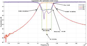
A first measurement with unpainted screw holes has led to poor filter performances. A second measurement has been made after silver-painting the screw holes, leading to much better parameters after filter tuning. The results are presented in Fig. 10 and Table I.
Fig. 10. S-parameters of the optimized filter (metal screws)
TABLE I. |
SIMULATED AND MEASURED FILTERS CHARACTERISTICS |
|||||
|
|
|
|
|
|
|
Screw |
|
f0 (GHz) |
Bandwidth |
Insertion |
Return |
Extracted |
type |
|
|
(MHz) |
loss (dB) |
loss (dB) |
Q0 |
Metal |
|
12.185 |
228 |
1.6 |
16.5 |
750 |
Plastic |
|
12.09 |
235 |
2.5 |
19.5 |
400 |
Similar filtering characteristics are obtained with metal or dielectric screws. Insertion loss is equal to 1.6dB for metal screws and 2.5dB with plastic screws. Thus, the dielectric losses inside the unknown plastic screws are more important than the metallic losses on the surface of the metal screws. Insertion losses are a bit high for both setups, but are acceptable considering the technology used. Moreover, they can probably be lowered by applying more layers of silver paint, especially in the screw holes. Metal screws offer a better selectivity, whereas the bandwidth is larger with plastic screws (235 MHz with plastic screws, and 228 MHz with metal screws). The plastic screws setup also presents 16.5dB return loss compared to 19.5dB for metal screws.
Finally, those measurements are coherent with the simulation of the4-poles Chebyshev-synthesized filter. The Q factor of the filter resonators has been obtained by fitting the measured S-parameters to theoretical curves obtained with coupling matrix synthesis.
VI. CONCLUSION
The idea of 3D printed plastic modular filters has been exploited in order to make n-poles bandpass filters for education purpose (microwave practical courses more
particularly). First, the problems of modular filters at screw joins and join blocks have been discussed. In order to improve the overall filter performances, dielectric screws tuning have been proposed. Then, in a second time, tuning possibilities according to the screw material have been compared. It has been shown that Teflon screws might be sufficient to adjust the response of the filter. A very good accuracy has been obtained with a maximum deviation of 60μm compared to the nomila dimensions.
Next, the design and manufacturing problems of a set of elementary blocks have been presented. The alignment function provided by alignment plots has been separated from the locking function provided by locking keys. Measurements of the 4-poles filter have been performed after silver painting the plastic parts and have shown a good agreement with the theoretical filter.
Finally the results shows that such modular filters offer a practical way to discover filtering design, since the filters can be built from elementary blocks having a specific filtering function, like an advanced "Lego" game. With some performance enhancements and a additive manufacturing using metal, they might be used as efficient modular filters.
ACKNOWLEDGMENT
The 3D printer was provided by the technological platform RAMSEI’S in Limoges, France. We want to thank M. Gramond for its availability and mastering of the 3D printer.
REFERENCES
[1]N. Jolly, O. Tantot, N. Delhote, S. Verdeyme, L. Estagerie, L. Carpentier, and D. Pacaud, “Wide range continuously high electrical performance tunable e-plane filter by mechanical translation”, In Microwave Conference (EuMC), 2014 44th European, pages 351–354, Oct 2014.
[2]P. Booth and E. V. Lluch, “Performance enhancement for waveguide filters using additive manufacturing”, In CNES/ESA International Workshop on Microwave Filters, volume 6, Mar 2015.
[3]G. Boudouris, “Cavités électromagnétiques”, Ed. Dunod, Paris (1971).
[4] Sichak, W.; Augenblick, |
H., |
"Tunable Waveguide Filters," |
in Proceedings of the IRE , |
vol.39, |
no.9, pp.1055-1059, Sept. 1951 |
doi: 10.1109/JRPROC.1951.273747 |
|
|
[5]S. Akatimagool and S. Choocadee, “The development of efficient cwfd simulation tools for waveguide band-pass filter design”, In Intelligent Signal Processing and Communications Systems (ISPACS), 2011 International Symposium on, pages 1–4, Dec 2011.
[6]Ji-Fuh Liang, H.-C. Chang, and K.A. Zaki, “Design and tolerance analysis of thick iris waveguide bandpass filters”, Magnetics, IEEE Transactions on, 29(2):1605–1608, Mar 1993.
[7]M.H.N. Potok, “Capacitive-iris-type mechanically tunable waveguide filters for the x-band”, Proceedings of the IEE - Part B: Electronic and Communication Engineering, 109(48):505–510, November 1962.
372