

диафрагмированные волноводные фильтры / 7035d8ee-4cac-4484-a08d-409df93533e6
.pdfReceived: 25 February 2019
DOI: 10.1002/mop.31929
R E S E A R C H A R T I C L E
A compact duplex filtering antenna using a T-shape probe-fed patch and hairpin resonators
Jia-Cheng Yuan | Ze-Ming Xie
School of Electronic and Information Engineering, South China University of Technology, Guangzhou, China
Correspondence
Jia-Cheng Yuan, School of Electronic and Information Engineering, South China University of Technology, Guangzhou, China.
Email: eeyjc@mail.scut.edu.cn
Funding information
Science and Technology Project of Guangzhou, Grant/Award Number: 201707010060
Abstract
A compact duplex filtering antenna using a T-shape probe-fed patch and hairpin resonators is proposed. First, the T-shape probe-fed patch is designed as a dual-band radiation element by connecting a microstrip line to the patch. Then the dual-band radiation element is coupled to two bandpass filters based on half-wavelength hairpin resonators directly to construct the duplex filtering antenna. The two modes of the dual-band radiation element function as last stage resonators, improving the selectivity of both the transmitting band and the receiving band, increasing the bandwidths, and enhancing the isolation. A prototype antenna is fabricated and measured. The measured results agree well with the simulated results.
K E Y W O R D S
duplex filtering antenna, hairpin resonator, high isolation
1 | INTRODUCTION
Duplex communication systems enable users to transmit and receive signals at the same time, so they play important roles in modern communications. Traditionally, a duplexer with high isolation should be used in a duplex wireless
communication system, enabling a transmitter and a receiver to share one antenna through a cable, as mentioned in Reference 1. In this traditional design, matching networks must be used to connect the duplexer and the antenna. This method adversely effects the communication efficiency because of the transmission loss introduced by the extra matching networks, and it also makes the system more complex and expensive. In the last decade, mobile communication has become increasingly popular, boosting the demands of integrated equipment, in which the transceiver and the antenna should be built together. As a result, compact duplex antennas that are free of extra matching networks and even duplexers have gained popularity.
Connecting a duplexer to an antenna directly is an effective way to cancel extra complex matching networks. In Reference 2, a substrate-integrated waveguide (SIW) cavity duplexer was integrated with a radiating patch to realize a duplex antenna with high isolation but narrow bandwidth. In Reference 3, a dual-band antenna was coupled to a duplexer that used a dual-mode resonator to combine two channel filters, achieving a port-to-port isolation over 30 dB.
Another simple method to build a duplex antenna system is to use two filtering antennas. However, it will take a larger space to accommodate two distinct antennas. In Reference 4, two distinct monopoles with filtering structures were placed together in close proximity to construct a novel duplex antenna system. In Reference 5, two aperture antennas were put together, and then two band-stop filters were inserted into their feeding lines to improve the isolation.
To design a more compact duplex antenna, one can use a dual port antenna connected to two channel filters directly. In Reference 6, a slot antenna was fed through two λ/4 SIWs. The two SIWs produce two channel filters and led to an isolation over 25 dB. The antenna was compact, but its bandwidths were narrow. In Reference 7, a rectangular aperture loaded with T- stubs was excited by two T-shape microstrip lines. This antenna exhibits self-duplex behavior, but its channel selectivity needs to be improved. In Reference 8, a microstrip patch with two slots was used as a dual-mode radiating element. A pair of microstrip resonators fed the patch. A second-order filtering characteristic was obtained, and the isolation was over 20 dB.
In this article, a compact duplex filtering antenna with increased bandwidth, improved selectivity and high isolation is proposed. A T-shape probe-fed microstrip patch antenna is used as a dual-mode radiation element and is coupled to two bandpass filters based on half-wavelength hairpin resonators. The two modes of the radiation element are used as the filtering resonators of the channel filters and are codesigned with
2506 |
|
© 2019 Wiley Periodicals, Inc. |
wileyonlinelibrary.com/journal/mop |
Microw Opt Technol Lett. 2019;61:2506–2512. |
|
YUAN AND XIE |
|
2507 |
|
|
|
||
|
|
|
|
FIGURE 1 The configuration of the T-shape probe-fed dual-band
radiation element [Color figure can be viewed at
wileyonlinelibrary.com]
the hairpin filters, so the filtering performance is improved. A prototype antenna for the RF front-end of a communication device is designed with a transmitting band of 2.36 to 2.49 GHz and a receiving band of 2.94 to 3.18 GHz. High isolation of over 36 dB in the transmitting band and over
31 dB in the receiving band is achieved. Good rectangle coefficients are observed in both channels.
2 | ANTENNA DESIGN
2.1 | Design of the dual-band radiation element
The configuration of the T-shape probe-fed dual-band radiation element is shown in Figure 1. The element consists of two substrates. A rectangular patch is printed on the top layer of the upper substrate. A small rectangular slot is cut into the rectangular patch to accommodate the T-shape probe. A ground plane is placed on the upper layer of the lower substrate. The T-shape probe is connected to a microstrip line on the bottom layer of the lower substrate through a hole in the ground plane. There is an air layer 4 mm in height exists between the two substrates. Both the substrate boards have a dielectric constant of 3.55, a loss tangent of 0.0027, and a thickness of 0.8 mm.
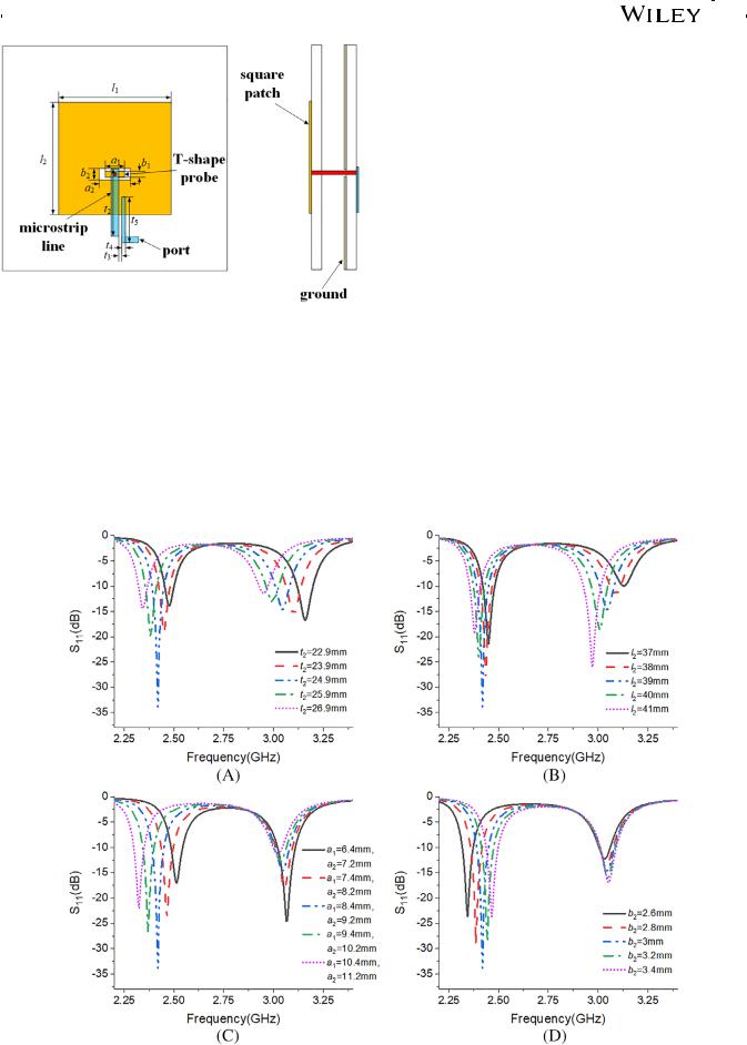
When the radiation element is excited as depicted in Figure 1, its return losses for various dimensions are simulated with HFSS software and shown in Figure 2. The dualband characteristic is observed in Figure 2. In Figure 2A,
FIGURE 2 The influences of the dimensions on the central frequencies of the two bands [Color figure can be viewed at
wileyonlinelibrary.com]

2508 |
|
|
YUAN AND XIE |
|
|
||
|
|
|
|
a1 = 8.4 mm, a2 = 9.2 mm, b1 = 2 mm, b2 = 3 mm, l1 = 39 mm, and l2 = 39 mm. In Figure 2B, a1 = 8.4 mm, a2 = 9.2 mm, b1 = 2 mm, b2 = 3 mm, l1 = 39 mm, and t2 = 24.9 mm. In Figure 2C, b1 = 2 mm, b2 = 3 mm, l1 = 39 mm, l2 = 39 mm, and t2 = 24.9 mm. In Figure 2D, a1 = 8.4 mm, a2 = 9.2 mm, b1 = 2 mm, l1 = 39 mm, l2 = 39 mm, and t2 = 24.9 mm.
Figure 2 depicts the influences of the dimensions on the central frequencies of the two bands. The length of the microstrip line under the ground plane, t2, influences both central frequencies. The length of the radiating patch, l2, mainly influences the central frequency of the high band. The length of the coupling microstrip line, a1, and the length of the rectangle slot on the patch, b2, mainly influence the central frequency of the low band.
The T-shape probe-fed antenna is then designed to operate at 2.4 GHz and 3.05 GHz. The dimensions are given in Table 1.
Figure 3A,B shows the current distributions at 2.4 GHz and 3.05 GHz. Notice that the patch has similar current
TABLE 1 The values of different parameters of the antenna
distributions but opposite current directions at the two frequencies, showing that the whole structure operates in different resonant modes. As a comparison, Figure 3C shows the current distribution of a probe-fed patch antenna operating in the TM10 mode. The three current distributions are similar. As a result, the dual-band radiation element will have similar radiation patterns for its two working bands
2.2 | Filter-integrated duplex antenna
Figure 4 shows the configuration of the codesigned duplex filtering antenna. (A), (B), and (C) in Figure 4 are the three views of the proposed antenna. The overall size is 90*90*5.6 mm3. The parameters of the antenna are shown in Table 1.
Port 1 feeds the dual-band radiation element through two hairpin resonators operating at 2.4 GHz. Port 2 feeds the dual-band radiation element through another two hairpin resonators operating at 3.05 GHz.
Parameter |
Value |
Parameter |
Value |
Parameter |
Value |
l1 |
39 mm |
l2 |
39 mm |
a1 |
8.4 mm |
|
|
|
|
|
|
a2 |
9.2 mm |
b1 |
2 mm |
b2 |
3 mm |
d1 |
0.9 mm |
d2 |
1.2 mm |
d3 |
0.4 mm |
|
|
|
|
|
|
d4 |
0.5 mm |
h |
0.8 mm |
h1 |
4 mm |
g1 |
0.5 mm |
g2 |
0.8 mm |
g3 |
0.4 mm |
|
|
|
|
|
|
g4 |
0.3 mm |
m1 |
16 mm |
m2 |
6.6 mm |
m3 |
6.5 mm |
m4 |
17.2 mm |
n1 |
14.2 mm |
n2 |
3.2 mm |
n3 |
3 mm |
v |
1 mm |
t1 |
2 mm |
t2 |
24.9 mm |
w |
1.75 mm |
s1 |
2 mm |
dy |
6 mm |
l |
90 mm |
t3 |
0.3 mm |
t4 |
0.5 mm |
t5 |
20 mm |
FIGURE 3 Current distributions of the T-shape probe-fed antenna and the probe-fed antenna. A, Current distribution of the T-shape probe-fed antenna at 2.4 GHz. B, Current distribution of the T-shape probe-fed antenna at 3.05 GHz. C, Current distribution of the probe-fed antenna at 3.05 GHz [Color figure can be viewed at wileyonlinelibrary.com]

YUAN AND XIE |
|
2509 |
|
|
|
||
|
|
|
|
FIGURE 4 The configuration of the codesigned duplex filtering
antenna [Color figure can be viewed at wileyonlinelibrary.com]
The topology of the filter-integrated duplex antenna is shown in Figure 5. Port 1 represents the transmitting port, and port 2 represents the receiving port. Resonator 1 and resonator 2 in the Tx channel represent the two hairpin resonators used in the transmitting channel filter. Resonator 3 and resonator 4 in the Rx channel represent the two hairpin resonators used in the receiving channel filter. f1 and f2 in the circles refer to the resonance frequencies of the resonators. Both filtering channels are integrated with the T-shape resonator-fed antenna by electromagnetic coupling. The coupling strength t can be adjusted by changing the coupling gap widths (d1 for the transmitting channel and g1 for the receiving channel).
In the transmitting band at 2.4 GHz, resonator 3 and resonator 4 do not work, and the T-shape resonator-fed antenna operates in the lower resonance mode. Thus, resonator 1, resonator 2, and the lower mode of the T-shape resonator-fed antenna compose a three-stage transmitting channel filter, as depicted in Figure 6. In the receiving band at 3.05 GHz, resonator 1 and resonator 2 do not work, and the T-shape resonator-fed antenna operates in the higher resonance
FIGURE 5 The topology diagram of the filter-integrated duplex antenna [Color figure can be viewed at wileyonlinelibrary.com]
FIGURE 6 The topology diagram of the duplex antenna when port 1 is excited [Color figure can be viewed at wileyonlinelibrary.com]
FIGURE 7 The topology diagram of the duplex antenna when port 2 is excited [Color figure can be viewed at wileyonlinelibrary.com]
mode. Thus, resonator 3, resonator 4, and the higher mode of the T-shape resonator-fed antenna compose a three-stage receiving channel filter, as depicted in Figure 7.
The radiation element is used as the last stage resonator in both the Tx band and the Rx band. Regardless of which port is excited, a three-stage filtering characteristic is obtained. As a result, both the bandwidth and the frequency selectivity of the duplex antenna are enhanced. When port 1 operates in the transmitting band, the Rx channel produces a stopband. When port 2 operates in the receiving band, the Tx channel produces a stopband. As a result, the port-to-port isolation is enhanced.
3 | SIMULATED AND MEASURED RESULTS
Figure 8 shows photographs of the top and bottom layers of the fabricated antenna. Figure 9 shows the simulated and

2510 |
|
|
YUAN AND XIE |
|
|
||
|
|
|
|
FIGURE 8 Photographs of the fabricated duplex antenna. A, Top layer of the top substrate. B, Bottom layer of the bottom substrate [Color figure can be viewed at wileyonlinelibrary.com]
FIGURE 9 Simulated and measured S-parameters of the duplex filtering antenna [Color figure can be viewed at wileyonlinelibrary.com]
FIGURE 10 Simulated and measured gains of the duplex filtering antenna [Color figure can be viewed at wileyonlinelibrary.com]
measured S-parameters. It can be derived from the curves in Figure 9 that third-order filtering performance is realized in each working band. The measured S-parameters agree well with the simulated S-parameters except for a small frequency shift due to the fabrication tolerance. The simulated results show that the impedance bandwidths of the antenna are 2.35 to 2.48 GHz (FBW = 5.38%) in the low band and 2.91 to 3.16 GHz (FBW = 8.23%) in the high band. The measured impedance bandwidths of the fabricated antenna are 2.36 to 2.49 GHz (FBW = 5.36%) in the low band and 2.94 to 3.18 GHz (FBW = 7.84%) in the high band. High isolation of over 36 dB in the Tx band and over 31 dB in the Rx band is realized according to the measured results.
Figure 10 displays the simulated and measured gains of the duplex antenna. The simulated results show that the antenna achieves a flat gain of 5.2 dBi when port 1 is excited and 7.5 dBi when port 2 is excited. Compared with the simulated gain curves, the measured gain curves show a small frequency shift and a small gain drop in the two working bands. The differences are caused by the fabrication tolerance. When one port is excited, the corresponding gain will decrease sharply and reach a very low level in the other
band. When port 1 is excited, the corresponding gain is suppressed to −14 dBi in the Rx band, and when port 2 is excited, the corresponding gain is suppressed to −16.6 dBi in the Tx band.
Figure 11A shows the simulated and measured radiation patterns at 2.4 GHz when port 1 is excited and port 2 is connected to a 50-Ω load. Figure 11B presents the simulated and measured radiation patterns when port 2 is excited and port 1 is connected to a 50-Ω load at 3.05 GHz. All the radiation patterns are normalized. Figure 11A,B shows that the antenna radiates with similar radiation patterns in the two operating bands. The radiation patterns for the two operating bands are similar to the radiation pattern of a typical microstrip patch antenna operating in the fundamental mode. This can be explained by the current distributions given in Figure 3. The measured radiation patterns agree well with the simulated radiation patterns in the H-plane for the two bands while the measured cross-polarization level in the E- plane is higher than the simulated results for the two bands. At 2.4 GHz, the measured HPBWs are 64 and 72 , and the measured cross-polarization discrimination levels are over 17 dB and 10 dB in the E-plane and H-plane, respectively.

YUAN AND XIE |
|
2511 |
|
|
|
||
|
|
|
|
FIGURE 11 Normalized simulated and measured radiation patterns of the duplex antenna [Color figure can be viewed at
wileyonlinelibrary.com]
At 3.05 GHz, the measured HPBWs are 64 and 68 , and the measured cross-polarization discrimination levels are over 21 dB and 12 dB in the E-plane and H-plane, respectively. The cross-polarization discrimination level is lower in the H-plane than in the E-plane at both 2.4 GHz and 3.05 GHz. This is due to the unwanted radiation caused by the transverse current around the rectangular slot in the radiating patch and the vertical current of the probe
characteristic is realized in each working band. The bandwidth of the antenna is increased, and the port-to-port isolation is enhanced. The measured bandwidth reaches 5.36% in the transmitting band and 7.84% in the receiving band. High isolation of over 36 dB in the transmitting band and over 31 dB in the receiving band is obtained. Furthermore, the duplex antenna achieves good frequency selectivity, flat gain and a compact size due to the codesign of the antenna and the filters.
4 | CONCLUSION
The design of a compact duplex filtering antenna using a T- shape probe-fed patch and hairpin resonators has been presented and analyzed. A T-shape probe-fed radiation element is designed to realize dual-band performance. Filters based on half-wavelength hairpin resonators are designed for each operating band. Then, the filters and the dual-band radiation element are integrated, and a third-order filtering
ACKNOWLEDGMENT
This work is supported by the Science and Technology Project of Guangzhou (201707010060).
ORCID
Jia-Cheng Yuan https://orcid.org/0000-0003-3867-4150

2512 |
|
|
YUAN AND XIE |
|
|
||
|
|
|
|
REFERENCES
[1]Hikita M, Sakiyama K, Hikino O, Kijima M. New low-distortion band-switching techniques for SAW antenna duplexers used in ultra-wide-band cellular phone. IEEE Trans Microw Theory Technol. 2004;52(1):38-45.
[2]Ho M-H, Hong W, Guan P-H, Chang G-G. Duplexing patch antenna design using substrate integrated waveguide cavities.
Microw Opt Technol Lett. 2017;59:3023-3030.
[3]Mao C, Gao S, Wang Y, Qin F, Chu Q. Compact highly integrated planar duplex antenna for wireless communications. IEEE Trans Microw Theory Technol. 2016;64(7):2006-2013.
[4]Li J, Zhai H, Shi J, Liu L, Nie Z, Hu D. Higher isolation dualfrequency distinct coupled antennas based on integrated filtering structures. Microw Opt Technol Lett. 2019;61:261-266.
[5]Zhang P, Xie Z. Frequency duplex function aperture antenna with high isolation. 2016 IEEE International Conference on Microwave and Millimeter Wave Technology (ICMMT); 2016: 644-646.
[6]Mukherjee S, Biswas A. Design of self-diplexing substrate integrated waveguide cavity-backed slot antenna. IEEE Trans Antennas Wirel Propag Lett. 2016;15:1775-1778.
[7]Lu Y, Lin Y. A mode-based design method for dual-band and selfdiplexing antennas using double T-stubs loaded aperture. IEEE Trans Antennas Propag. 2012;60(12):5596-5603.
[8]Lee Y, Tarng J, Chung S. A filtering diplexing antenna for dual-band operation with similar radiation patterns and low cross-polarization levels. IEEE Trans Antennas Wirel Propag Lett. 2017;16:58-61.
How to cite this article: Yuan J-C, Xie Z-M. A compact duplex filtering antenna using a T-shape probefed patch and hairpin resonators. Microw Opt Technol Lett. 2019;61:2506–2512. https://doi.org/10.1002/ mop.31929