

диафрагмированные волноводные фильтры / 1a3dda28-aa9d-48a4-917e-b20ef9575aa7
.pdfSee discussions, stats, and author profiles for this publication at: https://www.researchgate.net/publication/283104918
A review of antenna designs with harmonic suppression for wireless power transfer
Article · January 2015
CITATIONS |
|
READS |
|
5 |
|
1,162 |
|
5 authors, including: |
|
|
|
Nurzaimah Zainol |
Zahriladha Zakaria |
||
Technical University of Malaysia Malacca |
Universiti Teknikal Malaysia Melaka (UTeM), Malaysia |
||
12 PUBLICATIONS |
35 CITATIONS |
396 PUBLICATIONS |
3,330 CITATIONS |
SEE PROFILE |
|
SEE PROFILE |
|
Maisarah Abu |
|
Mawarni Yunus |
|
Universiti Teknikal Malaysia Malaysia |
Technical University of Malaysia Malacca |
||
74 PUBLICATIONS |
471 CITATIONS |
26 PUBLICATIONS |
102 CITATIONS |
SEE PROFILE |
|
SEE PROFILE |
|
All content following this page was uploaded by Nurzaimah Zainol on 20 February 2016.
The user has requested enhancement of the downloaded file.

VOL. 10, NO. 11, JUNE 2015 |
ISSN 1819-6608 |
ARPN Journal of Engineering and Applied Sciences
©2006-2015 Asian Research Publishing Network (ARPN). All rights reserved.
www.arpnjournals.com
A REVIEW OF ANTENNA DESIGNS WITH HARMONIC SUPPRESSION
FOR WIRELESS POWER TRANSFER
Nurzaimah Zainol, Zahriladha Zakaria, Maisarah Abu, Mohammed Saeed Jawad and Mawarni Mohamed Yunus
Microwave Research Group, Centre for Telecommunication Research and Innovation (CeTRI), Faculty of Electronics and Computer Engineering, Universiti Teknikal Malaysia Melaka (UTeM), Durian Tunggal, Melaka, Malaysia
E-Mail: nurzaimahzainol@ymail.com
ABSTRACT
This paper presents the investigation and characterization of antenna design with harmonic suppression for wireless power transfer to improve the overall system performance for RF/microwave front-end subsystems. This study focuses on the geometry of antenna to produce filtering and radiating element on antenna circuit itself by suppressing unwanted signal resonate at higher order other than spurious radiation. The research work about antenna with harmonic suppression was reviewed and analyzed in order to propose optimum topology that suits in energy scavenging and most importantly the new proposed structure must have high gain for overall system performance. The printed antenna which is microstrip patch antenna are mostly used due to efficient radiators, lightweight, simple construction and cost effectiveness. This antenna with harmonic suppression would be useful in microwave systems and can be integrated with rectenna system or wearable energy application where the systems give size reduction.
Keywords: microstrip patch antenna, defective ground structure, gain, harmonic suppression, resonator.
INTRODUCTION
Recently, fast growth of wireless power transmission application requires an efficient rectenna in delivering RF energy to be rectified into DC voltage for overall wireless power transfer system. Figure 1 illustrate wireless technology powered using ambient radiation which is widely used in many wireless communications such as agricultural management, healthcare management, factory monitoring and so forth. The wireless power transfer system must operate efficiently and the losses of energy during receiving and conversion of signal processes should be minimized by suppressing the unwanted signal. However, the interface between the antenna and the nonlinear circuit component such as diode [1-8] or FET for active integrated antenna (AIA) or rectenna system has a harmonic suppression filter which contributes additional insertion loss. The basic idea implementation of antenna with harmonic suppression is to avoid spurious radiation that easily produced at high-order resonant frequencies of the antenna from the circuits [9]. This weak signal then flow to the rectifier circuit for the RF-to-DC conversion and the process are repeated caused the output of the rectenna is low for wireless power transfer system [10-15].
One of the important issues found in [16] shows that the input impedance of the antenna design would allow the second harmonic at high-order frequency which occur at twice of its design frequency. However, higher order harmonic can be blocked as input impedance at higher order almost zero or unmatched.
Harmonic rejection technique: In this study on antenna element for harmonic suppression [17], the metallic structure with some modification on their basic design can be made to suppress the harmonic radiation as well as several techniques adopted by other research work such as slit and the stub in microstrip patch antenna, a circular sector patch antenna, a photonic band gap structure [18-19], defected ground structure (DGS) [20-22], shorting pin [23] and inserting slot [24-29].
To receive the transmitted signal effectively, the polarization of the antenna must be matched with the polarization of the wave, which is the same as the polarization of the transmitting antenna. Usually, the waves will be refracted or reflected if there are obstacles on the way of the signal transmission journey. However, the receiving antenna which capable of receiving both types of polarization such as dual circular polarized antenna can be used for wireless power transfer [30-35].
In this paper, a microstrip patch antenna with harmonic suppression is presented. The geometry of antenna with their design discrepancy was reviewed. The antenna performances as well as the electromagnetic fields of the structures are analyzed through simulations using CST Microwave Studio software. Through this work, we hope antenna harmonic suppression can improve the overall system performance by maximizing the power transfer at fundamental frequency only. The antenna design can be used for wearable energy application as well as rectenna system in wireless application.
1

VOL. 10, NO. 11, JUNE 2015 |
ISSN 1819-6608 |
ARPN Journal of Engineering and Applied Sciences
©2006-2015 Asian Research Publishing Network (ARPN). All rights reserved.
www.arpnjournals.com
Figure-1. Wireless technology powered using ambient radiation.
ANTENNA WITH HARMONIC SUPPRESSION
Several research works conducted recently as recorded in Table 1 featuring important of antenna design at 2.45GHz (ISM Band) applications [36] which not only act as radiator but also able to suppress the unwanted harmonics produced due to spurious radiation or excitation at high-order frequency. Several studies have been conducted on antenna harmonic rejection technique in order to proposed new design with improvement in overall system performance in term of its good return loss, voltage standing wave ratio (VSWR), radiation pattern, directivity and gain.
The best technique will be applied on the basic structure of radiating element to control the distribution of current flow on the patch antenna like slit, stub, defective ground structure or else. In turn, the performance of the overall system will be improved since the technique used will maximized power at the fundamental frequency and suppressed the radiated power at harmonic frequencies to achieve harmonic rejection characteristics. However, antenna harmonic suppression will have maximum power transfer at its design frequency if input impedance of antenna is 50Ω and perfectly matched with the characteristic impedance of transmission line in order to obtain maximum energy transfer between transmission feed line and an antenna.
2

VOL. 10, NO. 11, JUNE 2015 |
ISSN 1819-6608 |
ARPN Journal of Engineering and Applied Sciences
©2006-2015 Asian Research Publishing Network (ARPN). All rights reserved.
www.arpnjournals.com
Table-1. Various research work and associated harmonic rejection technique at 2.45GHz.
(Author (s), Year) |
Research’s title |
Antenna harmonic rejection |
Application |
||||
Technique |
Performance |
||||||
|
|
|
|||||
(Y.H.Suh, 2002) |
A High-Efficiency Dual-Frequency Rectenna for |
Open ended T- |
Efficiency: 82.7% |
2.45GHz and |
|||
[37] |
2.45 and 5.8GHz Wireless Power Transmission. |
strip CPS. |
|
|
|
5.8GHz |
|
|
Harmonic Suppression Characteristic of a CPW- |
CPW-fed |
S11< -10 dB |
|
|||
(J.Yeo, 2009) |
circular slot |
|
|||||
fed Circular Slot Antenna Using Single Slot On A |
E-plane: Bidirectional |
2.45GHz |
|||||
[38] |
with slot on |
||||||
Ground Conductor. |
H-plane: Omni-directional |
|
|||||
|
ground. |
|
|||||
|
|
|
|
|
|
||
(C.S Ong, 2010) |
A Compact 2x2 Circularly Polarized Antenna |
Unbalanced |
S11meas |
|
: <20 dB |
|
|
ARmeas |
|
: 0.15 dB |
2.45GHz |
||||
[39] |
Array For Energy Harvesting. |
slots. |
|
||||
Gainmeas |
:10.8 dBi |
|
|||||
|
|
|
|
||||
|
|
|
S11 |
|
: -25 dB |
|
|
(S.Riviere, 2010) |
A Compact Rectenna Device At Low Power Level. |
Slot at ground. |
Efficiency : 34% |
2.45GHz |
|||
[40] |
Gain |
|
: 4.3 dB |
||||
|
|
|
|
||||
|
|
|
Directivity : 6.5 dB |
|
|||
(H.Arai, 2011) |
Wireless Power Transfer System. |
Slit and stub. |
Efficiency : 53.0% |
2.45GHz |
|||
[41] |
|
|
|
||||
|
|
|
|
|
|
||
|
|
|
BW |
|
: 2.1GHz |
|
|
(Z.Harouni, 2011) |
A Dual Circularly Polarized 2.45GHz Rectenna |
Compact DCP |
3 dB (AR) : 705MHz |
|
|||
Efficiency : 63% |
2.45GHz |
||||||
[42] |
For Wireless Power Transmission. |
patch antenna. |
|||||
RHCPgain |
: 25.24 dB |
|
|||||
|
|
|
|
||||
|
|
|
LHCPgain |
: 6.8 dB |
|
||
|
|
|
S11 |
|
: -45 dB |
|
|
(F.J Huang, 2012) |
Design of Circular Polarization Antenna with |
Four right- |
Efficiency : 37.8% |
|
|||
BW |
|
: 137 MHz |
2.45GHz |
||||
[43] |
Harmonic Suppression For Rectenna Application. |
angles slit. |
|
||||
3 dB (AR : 30 MHz |
|
||||||
|
|
|
|
||||
|
|
|
ARmin |
|
: 0.32 dB |
|
|
(R.A Rahim, 2012) |
A 2.45GHz Circular Patch Antenna With |
|
S11 |
|
: -48 dB |
|
|
Harmonic Suppression For Wireless Power |
Slit and stub. |
|
2.45GHz |
||||
[44] |
|
|
|
||||
Transmission. |
|
|
|
|
|
||
|
|
|
|
|
|
||
(R.A Rahim, 2012) |
A 2.45GHz Harmonic Suppression Rectangular |
Slot and open |
S11 |
|
: -40 dB |
2.45GHz |
|
[45] |
Patch Antenna. |
stub. |
|
|
|
||
|
|
|
|
||||
|
|
|
BW |
|
: 70 MHz |
|
|
(J.Hung, 2012) |
Novel T-Shape Slot Couple Feed Dual Circular |
|
ARmin |
|
: 0.6 dB |
|
|
T-shape slot. |
3 dB (AR) |
: 40 MHz |
2.45GHz |
||||
[46] |
Polarized Rectenna. |
||||||
|
RHCPgain |
|
: 7.98 dBic |
|
|||
|
|
|
|
|
|||
|
|
|
LHCPgain |
: 8 dBic |
|
||
|
|
|
S11 |
|
: -20 dB |
|
|
|
Harmonics Suppression Single-Fed Dual- |
Circular slot |
Dirtot |
|
:9.887dBi |
|
|
(R.A Rahim, 2013) |
AR |
|
: 0.26 dB |
|
|||
Circularly Polarized Microstrip Patch Antenna For |
defected ground |
|
2.45GHz |
||||
[47] |
RHCPgain |
: 4.119 dB |
|||||
Future Wireless Power Transmission. |
structures. |
|
|||||
|
LHCPgain |
: 4.149dB |
|
||||
|
|
|
|
||||
|
|
|
Gaintot |
|
: 6.655dB |
|
|
|
|
|
VSWR |
|
: 1.054 |
|
|
(M.A Sennouni, 2013) |
Circular Polarized Square Patch Antenna Array |
Inclined slot. |
Main lobe |
2.45GHz |
|||
[48] |
For Wireless Power Transmission. |
Magnitude : 9.2 dBi |
|||||
|
|
||||||
|
|
|
Direction |
: 35.0o |
|
||
(F. Zhang, 2014) |
Design of a Compact Planar Rectenna For Wireless |
|
Gain |
: 2.05 dBi |
|
||
Planar topology. |
BW |
: 400MHz |
2.45GHz |
||||
[49] |
Power Transfer in the ISM Band. |
||||||
|
Size :122 x 122mm2 |
|
|||||
|
|
|
|
||||
(C.Y.D Sim, 2014) |
Microstrip-Fed Ring Slot Antenna Design With |
Ring slot. |
S11 |
: -24 dB |
2.45GHz |
||
[50] |
Wideband Harmonic Suppression. |
BW |
: 210 MHz |
||||
|
|
||||||
Harmonic suppression characteristic of a CPWfed circular slot antenna using single slot on a ground conductor was demonstrated by authors in [38] and this
design has multi-band rejection characteristic where the second and higher rejection bands are integer-multiple of the first band, and this is generated by inserting single slot
3
VOL. 10, NO. 11, JUNE 2015 |
ISSN 1819-6608 |
ARPN Journal of Engineering and Applied Sciences
©2006-2015 Asian Research Publishing Network (ARPN). All rights reserved.
www.arpnjournals.com
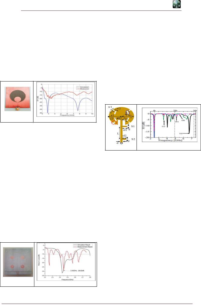
on a ground conductor of the antenna. The simulated and measured results shows good agreement and the integermultiple notch bands can be adjustable by varying the length of the slot on the ground plane. Figure-3 depict 70 mm x 80 mm of antenna dimension which notched frequency bands can be modified by adjusting the length of the arc-shaped slot itself. This circular slot antenna exhibits wider bandwidth illustrated in Figure 3 (c) due to antenna element was etched on 0.508mm thick Taconic RF-35 board which employing low relative permittivity, =3.5 [51].
(a)
(b)
Figure-3. CPW-fed circular slot antenna with an arcshaped slot on a ground conductor; (a) Fabricated
antenna; (b) Return loss characteristics without slot on ground conductor [38].
Authors in [39] proposed a compact 2x2 circularly polarized antenna array for energy harvesting. Figure-4 (a) depict the unbalanced slot on the radiating element of circular patch was adopted to obtain circular polarized and gives the simplest method of miniaturization. A 2x2 antenna array is designed using sequential rotation feeding scheme with a simulated axial ratio (AR) of more than 100MHz and gain of 13dBi. The higher gain is obtained due to arrays are very versatile that are used to synthesize a required pattern that cannot be achieved with a single element [52]. The measured return loss for antenna element is greater than -20dB and the minimum axial ratio (AR) of 0.21dB whereas the measured return loss for 2x2 arrays is - 28.8dB and the measured minimum axial ratio is 0.15dB with a 3dB AR bandwidth of 140MHz. The advantage of this design is circular polarized does not degrade the polarization loss between transmitter and receiver since the orientation is always perpendicular to the direction of propagation.
(a)
(b)
Figure-4. (a) Photograph of fabricated 2x2 antenna array; (b) Return loss of 2x2 arrays [39].
A circular microstrip patch antennas with slits and stub loading was demonstrated in Figure-5 proposed by researcher in [41]. The techniques adopted in this design able to suppress harmonic frequencies at higher order modes by inserting slits in the circular microstrip patch antenna and two stub on the feeding line. Based on Figure- 5 (b), the improved efficiency can be observed by applying both stubs and slit to the antenna design. The combination of techniques used to control the current flows on the radiating element and adding stub are required in this design for complete suppression of the second and third modes. As a result, second and third harmonic frequencies is suppressed to -0.26dB at 4.9GHx whereas -0.17 dB at 7.35GHz. The antenna design yield conversion efficiency of 53.0% for circular microstrip patch antenna with slits and stubs.
(b)
(a)
Figure-5. (a) Geometry of circular patch antena with slits and stub; (5(b)) Return loss characteristics; (a)
Without slits and stubs, (b) With stub and without slits,
(c) With slit and without stub, (d) With slits and stubs [41].
A microstrip patch antenna design with two peripheral cuts and four right angle slits embedded in the antenna design proposed in research work [43] was illustrated in Figure-6 (a) whereby Figure-6 (b) depict the return loss characteristics of simulation and measurement result. The geometry of the proposed antenna comprises a circular microstrip patch with dual peripheral cuts in order to excite circular polarization and four right angle slits used for harmonic rejection technique. The adopted CP antenna built on low cost FR4 substrate has a measured bandwidth of 137MHz and a 30MHz CP bandwidth (3 dB axial ratio). The reason why researcher used four right angle slits that are aligned symmetrical surrounding the patch center is to create the disturbance at the fundamental frequency without degrading it. This is because the slits extend and prolong the current path and perturb the higher order modes much more than the fundamental mode and adjusting certain parameter yields suppression at harmonic frequency. In fact, the measured copolarization radiation patterns in the xz-plane for the proposed antenna is quite obvious in Figure-6 c (i) as harmonic bands are suppressed effectively when compare with the reference circular microstrip disk antenna in Figure 6 c (ii) and the measured maximum CP
4

VOL. 10, NO. 11, JUNE 2015 |
ISSN 1819-6608 |
ARPN Journal of Engineering and Applied Sciences
©2006-2015 Asian Research Publishing Network (ARPN). All rights reserved.
www.arpnjournals.com
gain of the proposed antenna at the fundamental frequency |
yields 3.4 dBi. |
(a)
(b)
(i) |
(ii) |
Figure-6. (a) Geometry of antenna design; (b) Return loss; (c) Measured copolarization radiation pattern in the xz-plane; (i) proposed antenna;
(ii) reference circular microstrip disk antenna [43].
Researcher in [44] demonstrated a 2.45 GHz Circular Patch Antenna with Harmonic Suppression for Wireless Power Transmission. The proposed harmonic suppression circular patch antenna is excited with a microstrip feeding method and the advantage of this method is the connection of the patch and the feed is direct connection and they are on the same substrate to provide planar structure. The improvement of the input impedance matching has been made by the quarter-wave section in the transmission line feed. The slits at the patch and the stub at
the transmission line feed are proposed to suppress the harmonics at the higher order modes. Parallel slits function as controlling the current flows on the top patch. However, the current distribution on the circular patch is very complex and the harmonics still able to re-radiate. Thus, the open stub is introduced at the microstrip line feed to provide additional suppression on the harmonics frequencies and the geometry of antenna design can be observed in Figure-7. The antenna return loss is -48 dB at 2.45GHz and has realized gain 2.229 dB.
(a) |
(b) |
Figure-7. (a) Circular patch antenna, (i) Top view; (ii) Bottom view; (b) Return loss [44].
Besides, author in [45] proposed new design which is A 2.45 GHz Harmonic Suppression Rectangular Patch Antenna. The dimension value of patch shape can be obtained by calculating its transmission line model [53]. The techniques that are used in the suppression of harmonics are a notch-loaded and curvature slots at the antenna patch together with an open stub and inset feed transmission line. The partially ground with a circular slot at ground plane is also introduced to reduce the overall
patch size. The patch antenna gives -40dB return loss at 2.45GHz and suppress all the harmonics up to -1dB. In this design, the open stub and inset feed was adopted to suppress the harmonic for the second time whereas the curvature slot helps in increasing the bandwidth. The deployment of technique used in this structure able to suppress unwanted harmonics up to the third order effectively.
5

VOL. 10, NO. 11, JUNE 2015 |
ISSN 1819-6608 |
ARPN Journal of Engineering and Applied Sciences
©2006-2015 Asian Research Publishing Network (ARPN). All rights reserved.
www.arpnjournals.com
(i) |
(ii) |
(b) |
|
(a) |
|
|
|
Figure-8. (a) Proposed design; (i) Top view; (ii) Bottom view; (b) Return loss [45].
A novel design of a harmonic suppression singlefed dual-circularly polarized microstrip patch antenna for a rectenna system proposed in [47] which capable of receiving both types of circular polarization signal either RHCP or LHCP simultaneously and at the same time also able to filter the unwanted harmonic signals itself. These characteristics are achieved after introducing a circular slot defected ground structure to an array of nearly-square microstrip patch antenna with an offset inset microstrip feeding line and two open stubs on the feeding line. From a basic rectangular shape patch antenna, a nearly-square circularly polarized microstrip patch antenna is developed by a segment perturbation of the basic rectangular patch structure with an offset microstrip feeding line technique. To improve the input impedance matching, a quarter-wave impedance transformer section in the transmission line feed is applied. An overview of the antenna structure can be observed in Figure-9 and the antenna design yield maximized surface current distribution at fundamental frequency which illustrated in Figure-10 (a) while concentration of current flow is low at higher order modes depicted in Figure-10 (b) and Figure-10(c). The proposed antennas able to receive dual circular polarization of waves which can minimize the polarization mismatch loss during the transmission of signal. Thus, antenna design will received the transmitted signal effectively and act as filter at harmonic frequency.
(a) |
(b) |
(c) |
Figure-9. (a) Geometry of CP nearly-square patch antenna; (b) Front view; (c) Back view [47].
(a) 2.45GHz (b) 4.9GHz |
(c) 7.35 GHz) |
Figure-10. Surface current plot of the proposed antenna [47].
Circular polarized square patch antenna array for wireless power transmission was proposed by research work in [48] where 3x3 antenna array developed with attain their circular polarization using slot. The illustrated square patch antenna element with inclined slot in the center of radiating element can be seen in Figure-11 whereby input antenna is feeding by a microstrip line. Proposed design yield -31.59dB of its return loss and high directivity which is 9.256 dBi. Based on the result obtain, it indicate that the proposed design has the ability to focus energy in a particular direction and suits to wireless power transmission application. However, new arrangement of this design with additional V shaped slot at the corner also yields good performance [54].
6

VOL. 10, NO. 11, JUNE 2015 |
ISSN 1819-6608 |
ARPN Journal of Engineering and Applied Sciences
©2006-2015 Asian Research Publishing Network (ARPN). All rights reserved.
www.arpnjournals.com
(a)
(b)
Figure-11. (a) 3x3 slotted patches array; (b) Directivity of proposed design [48].
The recent research in [50] proposed microstripfed ring slot antenna design with wideband harmonic suppression. In order to suppress the additional harmonic modes excited by the ring slot, a single inverted U-shaped slot or defected ground structure is integrated into the CRSA. Through this, harmonic suppression approximately between 3 and 9 GHz was achieved for a wide bandwidth. This DGS can also be applied to other microstrip-fed ring slot antennas, such as square and triangular ring slot antennas and Figure 12 (a) depict clearly circular shape of
ring slot antenna that integrated with defective ground surface effectively suppress the unwanted harmonic frequency at high order modes. This geometry gives measured gain of 3.27 dBi and its corresponding efficiency was between 75% and 79%. The simulated and measurement result in Figure-12 (b) shows good performance of CRSA and proposed antenna. Thus, loading an inverted U-shaped DGS into CRSA achieves harmonic rejection technique effectively.
(a)
(b)
Figure-12. (a) Photograph of the proposed antenna; (b) Simulated and measurement return loss of CRSA and proposed antenna [50].
CONCLUSIONS
This review paper has presented a thorough introduction into the various harmonic rejection techniques for antenna harmonic suppression. The advantages and disadvantages of the various techniques have been highlighted and have presented a thorough comparison. Discussion has been focused on performance of each technique to seek the best topology suit for wireless power transfer system. Apart from that, each antenna harmonic suppression structure has pros and cons in terms of complexity, cost, size and its performance. However, some modification can be made to construct harmonic rejection capability in antenna design. Thus, a study on antenna with harmonic suppression has been reviewed and there are some design issues occurred in wireless power transfer that need to be considered including low conversion efficiency due to excitation at harmonic frequency and polarization mismatch. Improvements in overall system performance are important since maximum power must be transferred at fundamental frequency. The result of previous studies has
been compared to seek the best harmonic rejection technique and it is concluded that the combination of slit, stub and defective ground structure can achieve harmonic suppression characteristics. The verification process of the proposed antenna harmonic suppression will be further explored and implemented through an experiment in laboratory and field works. This new structure of antenna harmonic suppression is useful for RF/ microwave frontend subsystems where it will provide an attractive solution for the miniaturization of overall physical dimensions.
ACKNOWLEDGEMENT
The authors would like to express their thanks to the anonymous reviewers for their careful reading of the research article, and their constructive suggestions for the improvement of our work. The work was supported by UTeM under research grants RAGS/2013/FKEKK/TK02/02/B00031.
7

VOL. 10, NO. 11, JUNE 2015 |
ISSN 1819-6608 |
ARPN Journal of Engineering and Applied Sciences
©2006-2015 Asian Research Publishing Network (ARPN). All rights reserved.
www.arpnjournals.com
REFERENCES
[1]Zhongkun Ma and Guy A.E. Vandenbosch. 2014. Wideband Harmonic Rejection Filtenna for Wireless Power Transfer. IEEE Transactions on Antennas and Propagation. 62(1).
[2]Minoru Furukawa, Yoshiro Takahashi and Teruo Fujiwara. 2006. 5.8GHz Planar Hybrid Rectena for Wireless Powered Applications. Proceedings of AsiaPacific Microwave Conference.
[3]Rajiv Dahiya, A.K.Arora and V.R. Singh. 2013. RF Energy Harvesting for Hybrid Application: Review Analysis. International Journal of Innovative Technology and Exploring Engineering (IJITEE), ISSN: 2278-3075, 2(6).
[4]Sika Shrestha, Sun Kuk Noh and Dong You Choi. 2013. Review Article: Comparative Study of Antenna Designs for RF Energy Harvesting. International Journal of Antennas and Propagation, Article ID 385260.
[11]Jihwan Ahn, Woosung Lee, Young Joong Yoon and Young Do Kim. 2008. Planar Inverted F-Antenna with Suppressed Harmonic. IEEE.
[12]Shaoqiu Xiao, Li Jiang, Bing-Zhong Wang, and Jianpeng Wang. 2008. A Millimeter Wave Microstrip Antenna Array with Harmonics Suppression Elements. IEEE.
[13]Yunxue Xu, Shuxi Gong and Ying Guan. 2012. Coaxially Fed Microstrip Antenna for Harmonic Suppression. Electronics Letters. 48(15).
[14]Z. Zhang, Y.C Jiao and Z.B Weng. 2012. Design of 2.4GHz Power Divider with Harmonic Suppression. Electronics Letters. 48(12).
[15]Leszek S. Czarnecki. 2000. An Overview of Method of Harmonic Suppression in Distribution Systems. IEEE.
[16]Vesna Radisic, Siou Teck Chew, Yongxi Qian and Tatsuo Itoh. 1997. High-Efficiency Power Amplifier Integrated with Antenna. IEEE Microwave and Guided Wave Letters. 7(2).
[5]Sanghamitra Dasgupta, Bhaskar Gupta and Hiranmoy Saha. 2010. Development of Circular Microstrip Patch Antenna Array for Rectenna Application. IEEE INDICON.
[6]S.Riviere, F.Alicalapa, A.Douyere, J.D. Lan Sun Luk. 2010. A Compact Rectenna Device at Lower Power Level. Progress in Electromagnetics Research C. 16: 137-146.
[7]Xue-Xia Yang, Chao Jiang, Atef Z. Elsherbeni, Fan Yang and Ye-Qing Wang. 2012. A Novel Compact Printed Rectenna for Communication Systems. IEEE.
[8]Guo Min Yang, R. Jin, C.Vittoria, V.G. Harris and N.X. Sun. 2008. Small Ultra-Wideband (UWB) Bandpass Filter with Notched Band. IEEE Microwave and Wireless Components Letters. 18(3).
[9]X. Yin, H.Zhang, X.Y. Huang and H.Y.Xu. 2012. Spurious Modes Reduction in a Patch Antenna using an EBG-Based Microstrip Transmission Line Filter. Progress in Electromagnetics Research C. 25: 41-54.
[10]Fu Ren Hsiao, Tzung-Wern Chiou and Kin Lu Wong. 2001. Harmonic Control of a Square Microstrip Antenna Operated at the 1.8GHz Band. Proceeding of APMC, IEEE.
[17]Hyungrak Kim and Young Joong Yoon. 2003. Compact Microstrip-Fed Meander Slot Antenna for Harmonic Suppression. Electronics Letters. 39(10).
[18]Haiwen Liu, Zhengfan Li, Xiaowei Sun, and Junfa Mao. 2005. Harmonic Suppression with Photonic Bandgap and Defected Ground Structure for a Microstrip Patch Antenna. IEEE Microwave and Wireless Components Letters. 15(2).
[19]Nornikman Hassan, Badrul Hisham Ahmad, Mohamad Zoinol and Zahriladha Zakaria. 2013. Microstrip Patch Antenna with a Complementary Unit of Rhombic Split Ring Resonator (R-SRR) Structure. World Applied Sciences Journal 21(Special Issue of Engineering and Technology): 85-90, ISSN 1818-4952.
[20]Ashwani Kumar, A.K.Verma. 2009. Design of Compact Seven Poles Low Pass Filter using Defected Ground Structure. International Conference on Emerging Trends in Electronic and Photonic Devices and System (ELECTRO-2009).
[21]R.Sujith, S.Mridula, P.Binu, D.Laila, R.Dinesh and P.Mohanan. 2010. Compact CPW-Fed Ground Defected H-Shaped Slot Antenna with Harmonic Suppression and Stable Radiation Characteristics. Electronic Letters. 46(12).
8

VOL. 10, NO. 11, JUNE 2015 |
ISSN 1819-6608 |
ARPN Journal of Engineering and Applied Sciences
©2006-2015 Asian Research Publishing Network (ARPN). All rights reserved.
www.arpnjournals.com
[22]Sujoy Biswas, Debatosh Guha, and Chandrakanta Kumar. 2013. Control of Higher Harmonics and Their Radiations in Microstrip Antennas Using Compact Defected Ground Structures. IEEE Transactions on Antennas and Propagation. 61(6).
[23]Sewoong Kwon, Byoung Moo Lee, Young Joong Yoon, Woo Young Song and Jong-Gwak Yook. 2003. A Harmonic Suppression Antenna for an Active Integrated Antenna. IEEE Microwave and Wireless Components Letters. 13(2).
[24]Mohammad Saeid Ghaffarian and Gholamreza Moradi. 2011. A Novel Harmonic Suppressed Coplanar Waveguide (CPW)-Fed Slot Antenna. IEEE Antennas and Wireless Propagation Letters. Vol. 10.
[25]Ngoc-Anh Nguyen, Rashid Ahmad, Yun Taek Im, Yong Sun Shin and Seong-Ook Park. 2007. A T- Shaped Wide Slot Harmonic Suppression Antenna. IEEE Antennas and Wireless Propagation Letters. Vol. 6.
[26]Ngoc-Anh Nguyen and Seong-Ook Park. 2008. A Harmonic Suppression Antenna using T-Shaped Wide Slot. Proceedings of Iwat 2008, IEEE.
[27]Sang il Kwak, Jong Hwa Kwon, Dong-Uk Sim and Kihun Chang. 2010. Design of the Printed Slot Antenna Using Wiggly Line with Harmonic Suppression. IEEE Antennas and Wireless Propagation Letters. Vol. 9.
[28]Hyungrak Kim, Kwang Sun hwang, Kihun Chang and Young Joong Yoon, June 2004. Novel Slot Antennas for Harmonic Suppression. IEEE Microwave and Wireless Components Letters. 14(6).
[29]J.Yeo and D.Kim. 2009. Harmonic Suppression Characteristic of a CPW-Fed Circular Slot Antenna Using Single Slot on a Ground Conductor. Progress in Electromagnetics Research Letters. 11: 11-19.
[30]Yu Jiun Ren and Kai Chang. 2006. 5.8GHz Circularly Polarized Dual-Diode Rectenna and Rectenna Array for Microwave Power Transmission. IEEE Transactions on Microwave Theory and Techniques. 54(4).
[31]Berndie Strassner and Kai Chang. 2003. Highly Efficient C-Band Circularly Polarized Rectifying Antenna Array for Wireless Microwave Power
Transmission. IEEE Transactions on Antennas and Propagation. 51(6).
[32]Berndie Strassner and Kai chang. 2003. 5.8GHz Circularly Polarized Dual-Rhombic Loop Travelling Wave Rectifying Antenna for Low Power Density Wireless Power Transmission Applications. IEEE Transactions on Microwave Theory and Techniques. 51(5).
[33]Yunxue Xu, Shuxi Gong and Tao Hong. 2013. Circularly Polarized Slot Microstrip Antenna for Harmonic Suppression. IEEE Antennas and Wireless Propagation Letters. 13(12).
[34]Mohammod Ali, Guangli Yang and Roger Dougal. 2006. Miniature Circularly Polarized Rectenna with Reduced Out-of-Band Harmonics. IEEE Antennas and Wireless Propagation Letters. Vol. 5.
[35]Y.Y Gao, X.X Yang, C.Jiang and J.Y.Zhou , 2010. A Circularly Polarized Rectenna with Low Profile for Wireless Power Transmission. Progress in Electromagnetics Research Letters. 13: 41-49.
[36]Malaysian Communications and Multimedia Commission, December 2013. Requirements for Devices using Ultra-Wideband (UWB) Technology Operating in the frequency bands of 30MHz to 960MHz, 2.17GHz to 10.6GHz, 21.65GHz to 29.5GHz and 77GHz to 81GHz”, SKMM SRSP-549, UWB. p. 16.
[37]Young-Ho Suh and Kai Chang. 2002. A High Efficiency Dual-Frequency Rectenna for 2.45GHz and 5.8 GHz Wireless Power Transmissions. IEEE Transactions on Microwave Theory and Techniques. 50(7).
[38]J. Yeo and D.Kim. 2009. Harmonic Suppression Characteristic of a CPW-Fed Circular Slot Antenna Using Single Slot on a Ground Conductor. Progress in Electromagnetics Research Letters. 11: 11-19.
[39]C.S Ong, M.F.Karim, L.C.Ong, T.M.Chiam and A.Alphones. 2010. A Compact 2x2 Circularly Polarized Antenna Array for Energy Harvesting. Proceedings of Asia-Pacific Microwave Conference.
[40]S. Riviere, F.Alicalapa, A.Douyere and J.D.Lan Sun Luk. 2010. A Compact Rectenna Device at Low Power Level. Progress in Electromagnetics Research C. 16: 137-146.
9