

диафрагмированные волноводные фильтры / e9add6eb-a2cb-4c40-a5ea-d7cf608efe3d
.pdfThis article was downloaded by: [The University of Manchester Library] On: 12 October 2014, At: 05:39
Publisher: Taylor & Francis
Informa Ltd Registered in England and Wales Registered Number: 1072954 Registered office: Mortimer House, 37-41 Mortimer Street, London W1T 3JH, UK
Journal of Electromagnetic Waves and Applications
Publication details, including instructions for authors and subscription information: http://www.tandfonline.com/loi/tewa20
Substrate Integrated Folded
Waveguide (SIFW) Partial H-Plane
Filter with Quarter Wavelength
Resonators
Z. Wang a , Y. Jin b , R. Xu c , B. Yan d & W. Lin e
aSchool of Electronic Engineering, University of Electronic Science and Technology of China, Chengdu, Sichuan 610054, China
bSchool of Electronic Engineering, University of Electronic Science and Technology of China, Chengdu, Sichuan 610054, China
cSchool of Electronic Engineering, University of Electronic Science and Technology of China, Chengdu, Sichuan 610054, China
dSchool of Electronic Engineering, University of Electronic Science and Technology of China, Chengdu, Sichuan 610054, China
eSchool of Electronic Engineering, University of Electronic Science and Technology of China, Chengdu, Sichuan 610054, China
Published online: 03 Apr 2012.
To cite this article: Z. Wang , Y. Jin , R. Xu , B. Yan & W. Lin (2010) Substrate Integrated Folded Waveguide (SIFW) Partial H-Plane Filter with Quarter Wavelength Resonators, Journal of Electromagnetic Waves and Applications, 24:5-6, 607-617, DOI: 10.1163/156939310791036403
To link to this article: http://dx.doi.org/10.1163/156939310791036403
PLEASE SCROLL DOWN FOR ARTICLE
Taylor & Francis makes every effort to ensure the accuracy of all the information (the “Content”) contained in the publications on our platform. However, Taylor

Downloaded by [The University of Manchester Library] at 05:39 12 October 2014
& Francis, our agents, and our licensors make no representations or warranties whatsoever as to the accuracy, completeness, or suitability for any purpose
of the Content. Any opinions and views expressed in this publication are the opinions and views of the authors, and are not the views of or endorsed by Taylor & Francis. The accuracy of the Content should not be relied upon and should be independently verified with primary sources of information. Taylor and Francis shall not be liable for any losses, actions, claims, proceedings, demands, costs, expenses, damages, and other liabilities whatsoever or howsoever caused arising directly or indirectly in connection with, in relation to or arising out of the use of the Content.
This article may be used for research, teaching, and private study purposes. Any substantial or systematic reproduction, redistribution, reselling, loan, sublicensing, systematic supply, or distribution in any form to anyone is expressly forbidden. Terms & Conditions of access and use can be found at http:// www.tandfonline.com/page/terms-and-conditions

Downloaded by [The University of Manchester Library] at 05:39 12 October 2014
J. of Electromagn. Waves and Appl., Vol. 24, 607–617, 2010
SUBSTRATE INTEGRATED FOLDED WAVEGUIDE (SIFW) PARTIAL H-PLANE FILTER WITH QUARTER WAVELENGTH RESONATORS
Z. Wang, Y. Jin, R. Xu, B. Yan, and W. Lin
School of Electronic Engineering
University of Electronic Science and Technology of China Chengdu, Sichuan 610054, China
Abstract—In this paper, the design and experiment of a novel substrate integrated folded waveguide (SIFW) partial H-plane bandpass filter, consisting of quarter wavelength resonators, is presented. In the proposed filter, two adjacent quarter wavelength resonators are coupled by connecting an admittance inverter and an impedance inverter alternately. Here, the admittance inverter and impedance inverter are realized by H-plane slot of open-ended evanescent waveguide and H-plane septa of short-ended evanescent waveguide, respectively. In order to validate the new proposed topology, a four-pole narrowband bandpass filter is designed and fabricated using standard printed circuit board process. The tapered line is used as transition between SIFW and microstrip-line for easy integration and measurement. The measured results are in good agreement with simulated results.
1. INTRODUCTION
Microwave and millimeter-wave have become important working frequency with electronic technology development and are widely applied to radar, wireless communication and electronic antagonism [1– 5]. Advancement in these technologies brings the demands on high performance bandpass filters, with low cost and compact size. Conventional technologies of designing bandpass filters mainly include metallic waveguide and microstrip line. Conventional metallic waveguide bandpass filters have been widely used in microwave and millimeter-wave systems due to its merits of low insertion loss and high power handling capacity. But metallic waveguide filters are
Corresponding author: Z. Wang (wangzhigang19791@163.com).
Downloaded by [The University of Manchester Library] at 05:39 12 October 2014
608 Wang et al.
bulky, heavy, high cost, and also di cult to be integrated with planar circuit technology, being three-dimensional (3-D) structures [6– 11]. Microstrip line bandpass filters also have been widely applied to diversified systems for their compact size. However, microstrip line filters cannot provide required performances due to low Q-factor, especially at millimeter-wave frequencies [12–14].
Recently, a new planar waveguide structure called substrate integrated waveguide (SIW) is proposed [15, 16], which is realized by periodical metallic via-holes on low loss substrate through conventional planar circuit processes, such as printed circuit board (PCB) process and low temperature co-fired ceramic (LTCC) technology. Such a class of waveguides has the advantages of high Q-factor, convenient integration, mass-producible, low cost, etc. Diversified filters based on SIW have been realized [17–21, 30, 31]. However, compared with microstrip line or stripline components, the width of SIW may be too large for some circuits. In order to reduce the width, the concept and geometry of substrate integrated folded waveguides (SIFW) are presented [22, 23]. In [22] and [23], two di erent SIFW structures are proposed, which keep the advantages of SIW, but the width is nearly reduced in half. Several components have been studied to demonstrate these structures [23–26, 32].
Based on the coupling matrix synthesis method for microwave bandpass filters, this paper presents the design and development of a SIFW quarter wavelength resonator partial H-plane bandpass filter, by using two di erent types of evanescent waveguide, namely H- plane slot and H-plane septa. A tapered transition from SIFW to microstrip line is also designed for the convenience of measurement and integration. The proposed filter has advantages of low cost and mass-producible property. The filter is significantly smaller than its metallic folded waveguide counterpart [10, 11], and, more importantly, its performances are defined purely by the metallization on the central metal layer, which can be defined very accurately using photolithography. The length of resonators is quarter wavelength, so that the total length is shorter than the designed SIFW bandpass filter in [23]. In addition, compared with the filter in [23], the proposed filter has the sharp skirt characteristic and improved spurious responses.
2. DESIGN OF THE SIFW PARTIAL H-PLANE BANDPASS FILTER
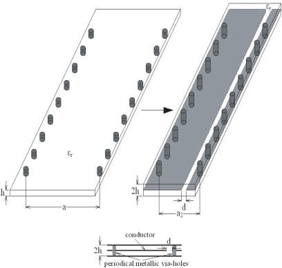
The configuration of an SIW is shown in Fig. 1(a) and that of an SIFW in Fig. 1(b), with a2 being the width of the SIFW and d the spacing between the H-plane metal vane and the right sidewall of metallic via-
Downloaded by [The University of Manchester Library] at 05:39 12 October 2014
SIFW partial H-plane filter with quarter wavelength resonators |
609 |
holes. Fig. 1(c) is the side view of the SIFW. It can be seen that the SIFW is a SIW whose sides have been folded together from its central part. Metallic via-holes are used to synthesize the conducting side walls. The diameter and spacing of the holes is much shorter than the operating wavelength and therefore is equivalent to a conducting wall [16]. The top, bottom and central metal layers are formed by patterned metallization on the surfaces of substrates. The thickness 2h of the SIFW of Fig. 1(b) is twice that of the h of the SIW in Fig. 1(a), while its width a2 is nearly half of a. The fundamental mode of the SIFW is TE10 mode as the SIW. The maximum field is presented at the edge of the guide between the middle conductor and sidewall. For the correct choice of a2, h and d, the SIFW can be made to have the identical propagation characteristics to that of the SIW [27].
(a) |
(b) |
(c)
Figure 1. Configuration of SIW and SIFW: (a) SIW, (b) SIFW, (c) the side view of the SIFW.

Downloaded by [The University of Manchester Library] at 05:39 12 October 2014
610 |
Wang et al. |
The proposed SIFW partial H-plane bandpass filter with quarter wavelength resonators is shown in Fig. 2. This structure provides a more compact bandpass filter compared with metallic waveguide counterpart. In the proposed SIFW partial H-plane filter, two adjacent quarter wavelength resonators are coupled by connecting an admittance inverter and an impedance inverter alternately. Here, the admittance inverter and impedance inverter are realized by H- plane slot of open-ended evanescent waveguide and H-plane septa of short-ended evanescent waveguide, respectively, as shown in Fig. 2. A tapered transition from SIFW to microstrip is employed for the convenience of test and integration. The design of the tapered transition requires simultaneous matching of the fields and impedance. Several transition designs have been reported [15, 23]. It is easy to achieve a fairly good field matching by their dominant vertical E-field components. Their impedance is also matched using the tapered line without significant disturbance of their vertical E-field components. A commercial full-wave 3-D FEM simulator (Ansoft HFSS) is used to analyze and optimize the transition structure. The geometric dimensions of transition designed are shown in Table 1.
(a)
(b)
Figure 2. The proposed SIFW partial H-plane filter with quarter wavelength resonators: (a) 3-D structure, (b) layout of the central metal layer.

Downloaded by [The University of Manchester Library] at 05:39 12 October 2014
SIFW partial H-plane filter with quarter wavelength resonators |
611 |
Table 1. The geometric dimensions of the designed SIFW partial H-plane bandpass filter (unit: mm).
l1 |
l2 |
l3 |
l4 |
l5 |
l6 |
w |
w1 |
4 |
6 |
5.2 |
5.2 |
6 |
4 |
0.75 |
0.6 |
|
|
|
|
|
|
|
|
w2 |
w3 |
w4 |
w5 |
sw |
tw |
S1 |
S2 |
9.24 |
2 |
9.6 |
0.6 |
0.4 |
2.22 |
4.3 |
5.6 |
|
|
|
|
|
|
|
|
S3 |
d |
Q |
P |
a2 |
tl |
h |
|
4.3 |
1.2 |
0.5 |
0.7 |
9.1 |
7.42 |
0.254 |
|
The classical design theories of filter have been consummated since long time ago. In this paper, the procedures to design convectional parallel-coupled bandpass filter can be applied to the design of the proposed bandpass filter [28]. The bandpass filter can be designed with a set of parameters consisting of external quality factors Qe1, Qen and coupling coe cients Ki,j . First of all, the element values for Chebyshev lowpass prototype can be calculated as follows [29]:
g0 = 1.0, |
|
|
|
= |
|
2 sin |
|
π |
|
|
|
|
|
|
|
|
|
|
||||||
|
g1 |
2n |
|
|
|
|
|
|
|
|
||||||||||||||
|
|
|
r |
|
|
|
|
|
|
|
|
|
|
|
|
|
||||||||
|
|
|
|
|
|
|
|
|
|
|
|
|
|
|
|
|
|
|
|
|
|
|
||
|
|
|
|
|
(2i |
1)π |
|
|
|
|
|
(2i 3)π |
|
|
|
|
|
|||||||
|
|
4 sin |
|
|
− |
|
|
|
sin |
|
− |
|
|
|
|
|
|
|||||||
|
|
|
|
|
|
|
2n |
|
|
|
|
|
|
|
|
2n |
|
|
|
|
|
|
||
|
|
|
|
|
|
|
|
|
|
|
|
|
|
|
|
|
|
|
|
|
|
|
|
|
gigi 1 = |
|
|
|
|
|
|
|
|
|
|
|
|
|
|
|
|
|
|
, for i = 2, 3, . . . n (1) |
|||||
|
|
|
|
|
|
|
|
|
2 (i |
|
1)π |
|
||||||||||||
|
− |
|
|
|
2 |
|
|
|
|
|
|
|
|
|
|
|
|
|||||||
|
|
|
|
|
|
|
|
|
|
|
|
|
|
|
|
|
|
|
|
|
|
|
||
|
|
|
|
γ |
|
+ sin |
|
|
− |
|
β |
|
|
|
|
|
||||||||
|
|
|
|
|
|
|
|
|
|
|
|
|
|
|
|
n |
|
|
|
|
|
|||
|
|
|
|
|
|
|
|
|
|
|
|
|
|
|
|
|
|
|
4 |
|
|
|
|
|
|
|
|
|
|
|
|
|
|
|
|
|
|
|
|
|
|
|
|
|
|
|
|||
|
|
|
|
|
|
|
|
|
or |
|
|
coth |
|
(n even) |
||||||||||
|
|
|
|
|
|
|
|
|
|
|
|
|||||||||||||
gn+1 = 1(n odd) |
|
|
|
|
|
|||||||||||||||||||
|
|
|
|
|
|
|
|
|
|
|
|
|
|
|
|
|
|
|
|
|
|
|
|
|
|
|
|
|
|
|
|
|
|
|
|
|
|
|
|
|
|
|
|
|
|
|
|
|
|
where |
β = ln coth |
17.37 |
|
, |
|
γ = sinh |
2n |
|||||||||||||||||
|
|
|
|
|
|
|
|
|
|
LAr |
|
|
|
|
|
|
β |
|
||||||
Secondly, the design parameters of BPF, i.e., the coupling coe cients (Kij ) and external quality factors (Qe), can be determined by the formulas [29]:
Qe1 = |
g0g1 |
|
|
||
F BW |
|
||||
Qen = |
g0g1 |
|
(2) |
||
F BW |
|||||
|
|
||||
|
F BW |
|
|||
Ki,i+1 = √ |
|
for i = 1 to (n − 1) |
|||
gigi+1 |
|||||
where gi’s are the element values of Chebyshev lowpass prototype filter, FBW the fractional bandwidth, and n the order of the filter.

Downloaded by [The University of Manchester Library] at 05:39 12 October 2014
612 |
Wang et al. |
(a) |
|
(b) |
Figure 3. Unit cells of the proposed SIFW partial H-plane filter: (a) partial H-plane septa, (b) partial H-plane slot.
(a)
(b)
Figure 4. (a) Impedance inverter (K-inverter) for H-plane septa, (b) Admittance inverter (J-inverter) for H-plane slot.
The next step of the filter design is to characterize the coupling coe cients and external quality factors in terms of physical structures, so that the physical dimensions of the filter can be determined against the design parameters in Equation (2). There are two di erent types of coupling structures encountered in the filter design, i.e., H-plane slot of open-ended evanescent waveguide and H-plane septa of short-ended evanescent waveguide, respectively, as shown in Fig. 3. The H-plane septa of short-ended evanescent waveguide can be represented with an impedance inverter (K-inverter) circuit, as shown in Fig. 4(a). The H- plane slot of open-ended evanescent waveguide can be represented with an admittance inverter (J-inverter) circuit, as shown in Fig. 4(b). As far as the coupling between any pair of coupled resonators is concerned, it is quite easy to identify, in the full-wave EM simulation, the two split resonant frequencies fa and fb, which are related to the coupling

Downloaded by [The University of Manchester Library] at 05:39 12 October 2014
SIFW partial H-plane filter with quarter wavelength resonators |
613 |
coe cients as [29]:
Ki,j = |
fb2 |
− fa2 |
(3) |
||
f 2 |
+ f 2 |
||||
|
|
b |
|
a |
|
The external quality factor can be modeled by [29]: |
|
||||
Qe = |
|
f0 |
|
(4) |
|
|
δf3 dB |
||||
where f0 and δf3 dB are the resonant frequency and the 3-dB bandwidth of the input or output resonator when it alone is externally excited by the tapered line transition. Then, the relationships between the physical dimensions of the filter and coupling coe cients (Kij ), between the physical dimensions of the filter and external quality factors (Qe) can be obtained.
Thus, according to the design requirements of filter, the initial physical dimensions of filter can be determined.
Finally, a commercial full-wave 3-D FEM simulator Ansoft HFSS is used to analyze and optimize the filter after the initial design. To validate the proposed novel partial H-plane filter based on SIFW, a four-pole narrowband bandpass filter is designed using a substrate with relative dielectric of 2.22 and thickness of 0.254 mm. The specification for the filter is four-pole, 0.01 dB passband ripple, center frequency f0 = 10 GHz, and the fractional bandwidth = 4% (400 MHz). Ansoft HFSS is used to simulate and optimize the filter after initial design. To enable measurement, a tapered transition to SIFW has been developed, as shown in Fig. 2. The geometric dimensions are determined as shown in Table 1.
3. FABRICATION AND MEASUREMENTS
The filter is fabricated on a substrate with relative dielectric constant of 2.22 and thickness of 0.254 mm, using standard printed circuit board process. Photograph of the fabricated partial H-plane filter is shown in Fig. 5 (including a pair of test cavity with SMA connectors). The filter is considerably smaller than its metallic waveguide counterpart.
The measurements were taken using Agilent E8363B vector network analyzer (VNA). The simulated and measured responses of the filter are shown in Fig. 6. It can be seen from Fig. 6 that the operating bandwidth of measurement results is little smaller than that of simulation results, and insertion loss is larger, which could be attributed to the tolerance of manufacture and relativity permittivity, dielectric loss, high order modes, material and radiation loss. In spite of these, the simulated and measured results still have a good

Downloaded by [The University of Manchester Library] at 05:39 12 October 2014
614 Wang et al.
agreement. The fabricated filter exhibits 1.7 dB insertion loss at center frequency 10 GHz (including the loss of transitions and the influences of SMA connectors), a 1 dB-bandwidth of 315 MHz, and the return loss better than 10 dB. The measured out of band rejection is better than 52 dB and 37 dB at 1 GHz lower and higher separation from the center frequency of 10 GHz. Obviously, the proposed filter has excellent selectivity, the rejection in down and up stop-band is equally excellent.
Figure 5. Photograph of the fabricated four-pole partial H-plane filter (including test cavity).
|
0 |
|
|
|
|
|
-20 |
|
|
|
|
(dB) |
|
|
|
|
|
Magnitude |
-40 |
|
|
|
|
|
|
|
|
|
|
|
-60 |
|
|
Simulated (S11) |
|
|
|
|
|
|
|
|
|
|
|
Simulated (S21) |
|
|
|
|
|
Measured (S11) |
|
|
|
|
|
Measured (S21) |
|
|
-80 |
|
|
|
|
|
6 |
8 |
10 |
12 |
14 |
Frequency (GHz)
Figure 6. Simulated and measured S-parameters of the fabricated four-pole partial H-plane filter with quarter wavelength resonators.
4. CONCLUSION
A novel SIFW partial H-plane bandpass filter with quarter wavelength resonators, using H-plane slot and H-plane septa as coupling schemes, has been developed and investigated in this paper. The proposed filter is considerably smaller than its metallic waveguide counterpart.