

диафрагмированные волноводные фильтры / b8f210ff-ebb9-4889-b924-258b199a81f2
.pdfProceedings of the 38th European Microwave Conference
E-plane Filters with Selectively Located Transmission Zeros
R.López-Villarroya, G.Goussetis, J.S. Hong, J.L. Gómez -Tornero*
RF and Microwave Research Group, Heriot Watt University, Riccarton, Edinburgh, EH14 4AS, Scotland, UK *Universidad Politécnica de Cartagena
Abstract—The possibility to produce transmission zeros at selectively located finite frequencies is reported for bandpass filters compatible with the conventional E-plane topology. The structure is based on etching resonant apertures on a thin allmetal E-plane insert, which are coupled in parallel. We demonstrate that different combinations of the horizontal (overlap) length and vertical distance between the resonators can produce the same coupling coefficient while introducing transmission zeros at different frequencies. This allows for selective location of the transmission zero for each pair of resonators, which is demonstrated by means of 2nd order filter examples. Two prototypes have been designed and fabricated producing sharp roll-off at either the lower or higher cutoff frequency. Good agreement between numerical and experimental results validate our argument. Moreover compared to conventional E-plane filters, the parallel coupling topology is shown to reduce the overall dimensions by about 50% and shift the spurious resonance by about 1GHz at x-band while maintaining the low-cost and mass-producible characteristics.
b |
|
a |
Lr1 |
Ls10 |
|
|
||
s |
s1su |
|
b |
|
s2sd |
|
|
|
Ls23 |
Lr2 Ls12 |
|
I. INTRODUCTION
All-metal inserts mounted in the E-plane of a split block waveguide housing is a well-established technique for realising low-cost and mass producible microwave configurations, such as bandpass filters [1-8]. However, despite their favourable characteristics, E-plane filters suffer from bulky size and stopband performance that may often be too low for many applications, such as multiplexers. Furthermore, many multi-channel or diplexer applications require filters with sharp cutoff, in order to accommodate for closely spaced frequency channels and avoid cross-talk.
The requirement of steep attenuation slopes is very conveniently addressed with transmission zeros positioned close to the cutoff of the filter, rather than increasing the order of the filter, which in turn would increase the size and the losses. Similarly, the out-of-band rejection performance can be locally improved by selectively positioning transmission zeros. To address this requirement, Ofli et. al. recently proposed a folded configuration that allows cross-coupling between the resonators in order to produce a pseudo-elliptic response [5], at the cost of fabrication simplicity. In [4] a 3rd order E-plane filter compatible with the thin all-metal insert split-block housing E-plane topology was demonstrated to produce sharp higher frequency roll-off implementing a transmission zero. The topology in [7] involved both series and parallel coupled resonators and it was argued that the
Fig. 1 Schematic layout of the open ended oven concept
transmission zero emerges due to cross coupling between the three resonators.
In this paper we present the possibility to selectively position transmission zeros using a pair of parallel coupled resonators. The resonators are etched as half wavelength slots in the all-metal E-plane insert and are arranged symmetrically in the waveguide as shown in the schematic of Fig. 1. This coupling arrangement produces a transmission zero at finite frequencies. Moreover, it allows two free variables in controlling the coupling coefficient in the passband, namely the overlap length (horizontal) and the vertical separation. Different combinations of the two parameters allow for selective positioning of the transmission zero. In the following we demonstrate this by means of parametric simulated results as well as numerical and experimental results in an example involving second order filters.
II. SELECTIVE LOCATION OF THE TRANSMISSION ZERO
In order to demonstrate the possibility to selectively position a transmission zero with a pair of resonators arranged as in Fig. 1, here we present a parametric study based on simulated results. HFSS has been employed for the simulations throughout this paper, assuming an 2D planar
978-2-87487-006-4 ♥ 2008 EuMA |
733 |
October 2008, Amsterdam, The Netherlands |

(a)
(b)
Fig 2: Paramateric study of (a) the coupling coefficient magnitude and (b) the transmission zero location for a pair of synchronously tuned resonators (su= sd) arranged as in Fig. 1. Dimensions (in mm) Lr1= Lr2= 16, s1= s2= 2.1
metal insert. We model a pair of synchronously tuned resonators at 8.9GHz (i.e. Lr1= Lr2= 16mm, s1= s2= 2.1mm su= sd) and excite them very weakly so that we can study the split of the odd and even resonance [8]. Weak excitation is ensured by long input and output coupling septa, here Ls10= Ls23= 8mm. Fig. 2a shows the magnitude of the coupling coefficient as the vertical separation s between the resonators increases for different overlapping lengths Ls12.
For the lower values of Ls12, the coupling strength reduces with increasing separation. For values of Ls12 in the middle range of Fig. 2a, the magnitude of the coupling coefficient appears to obtain a minimum value for a certain s. For the two highest values of Ls12, the curves appear to be increasing. This is because Fig. 2a plots the magnitude of the coupling coefficient. Careful investigation along a curve with a minimum reveals that the even and odd resonance swap in frequency close to the minimum, which corresponds to change in sign of the coupling coefficient into a negative value.
Hence for the larger / smaller values of Ls12, for which the coupling coefficient appears to increase / reduce
monotonically with the separation s, the coupling coefficient is of opposite sign. Similarly, for the curves with a minimum, the coupling coefficient changes sign away from it.
(a)
(b)
Fig 3: Second order filters with passband centred approximately at 8.9GHz and transmission zeros located in the (a) upper and (b) lower stopband. Dimensions (in mm) (a) Lr1= Lr2= 16, s1= s2= 2.1, s= 1.7 and (b) varying dimensions (see main document)
From the same set of simulations, the location of the transmission zero, identified as a sharp minimum in the transmission coefficient, is reported in Fig. 2b. As shown, the transmission zero drops with increasing separation s in all cases. Careful observation reveals that the transmission zero emerges below the resonant frequency (8.9GHz) for the cases with negative coupling coefficient. This allows for selective positioning of the transmission zero at the upper or lower stopband of the filter.
In order to demonstrate this, Fig. 3 presents a series of approximate second order filter designs with passbands centred at 8.9GHz and different locations of the transmission zeros. In particular, Fig. 3a shows a parametric study varying the overlap length Ls12 for an arrangement with Lr1= Lr2= 16mm, s1= s2= 2.1mm, s= 1.7mm, which produces a transmission zero in the upper stopband. As shown, the increasing Ls12 results in narrower passbands, due to the reduced coupling coefficient between the two resonators (see Fig. 2a). Moreover, in accordance to Fig. 2b, for increasing Ls12, the transmission zero emerges at increasingly lower frequencies approaching the upper cutoff. A similar graph is shown in Fig. 3b for transmission zeros located in the lower stopband. To illustrate the possibility to selectively position
734
(a) |
(b) |
(d) |
(c) |
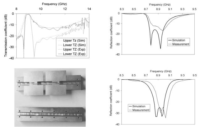
Fig 4: (a) Simulated and measured transmission coefficient for the Lower TZ and Upper TZ filter prototypes (b) Simulated and measured reflection coefficient for the Lower TZ filter prototype (c) Simulated and measured reflection coefficient for the Upper TZ filter prototype (d) Photograph of the fabricated prototypes (Lower TZ prototype on right hand side). Dimensions in mm: Lower TZ prototype are Lr1= Lr2= 16, s1= s2= 2.1, s= 1.5 Ls12= 11.4 Upper TZ prototype are Lr1= Lr2= 16, s1= s2= 2.1, s= 1.7, Ls12= 8.4
the transmission zero in this case, several parameters of the filter had to be adjusted. Nevertheless, as shown in Fig 3a and 3b, the arrangement of Fig. 1 allows for selective location of the transmission zeros on either side of the passband.
III. PROTOTYPES: NUMERICAL AND EXPERIMENTAL DESIGNS
To demonstrate the above, two second order filter x-band prototypes have been designed to produce approximately the same passband characteristics but a sharp roll-off on either the lower or higher frequency cutoff. In the following these will be referred to as the Lower and Upper Transmission Zero (TZ) prototype respectively. The dimensions (in mm) for the Lower
TZ prototype are Lr1= Lr2= 16, s1= s2= 2.1, s= 1.5 Ls12= 11.4 while for the Upper TZ prototype are Lr1= Lr2= 16, s1= s2= 2.1,
s= 1.7, Ls12= 8.4. The simulated transmission coefficient for the two prototypes is shown in Fig. 4a (dashed lines). The simulated reflection coefficient is shown in Fig. 4b and 4c for the Lower and Upper TZ prototype respectively.
The passband for both filters is to a good approximation between 8.75GHz and 9.10GHz. Although there is a difference of about 10dB in the maximum value of the reflection coefficient, both maintain reflection levels below - 15dB and are suitable for demonstrating the selective positioning of the transmission zero. The transmission zeros are located at 8.6GHz and 9.45GHz for the Lower TZ and
Upper TZ prototype respectively. This produces a sharp rolloff rate at the lower and upper cutoff frequency respectively. The spurious harmonic resonance is above 14GHz for both prototypes. This is more than 1GHz improvement compared to the conventional E-plane filters, e.g. [8]. Moreover, the total lengths are 22.4mm and 25.4mm for the Lower TZ and Upper TZ respectively. This compares to about 46mm required for a conventional second order E-plane filter [8], corresponding to about 50% size reduction.
In order to validate the simulations, the two prototypes have been fabricated. A 100µm copper foil has been routed to etch the filter circuit, which was mounted in a machined brass waveguide housing. A photograph of the two prototypes is shown in Fig. 4d. The prototypes were measured in an HP8510 vector network analyser, using commercial x-band flanges. The calibration was made to the level of the coaxial cable. The comparison of the simulated with the measured results is shown in Fig.4a-c, and are in good agreement, validating the possibility to selectively locate the transmission zero. Fig. 4b and 4c reveal a frequency shift between 50 and 100MHz. This is attributed to relative convergence of our simulations, experimental tolerances as well as the fact that the simulations did not account for the finite thickness of the copper insert.
735
IV. CONCLUSIONS
The selective positioning of transmission zeros in a bandpass filter compatible with the low-cost and massproducible characteristics of thin all-metal insert split-block E-plane topology has been demonstrated. By means of parametric studies involving two synchronously tuned resonators, we have shown that it is possible to almost independently control the value of the coupling coefficient (including negative values) and the location of the transmission zeros. Good agreement between simulated and experimental results for two prototypes with sharp lower and upper cutoff respectively have validated the performance enhancement. Moreover, the prototypes outperformed conventional E-plane filters in the upper stopband bandwidth (extended by 1GHz at x-band) and overall physical size (about 50% miniaturisation).
.
REFERENCES
[1]Vahldieck R., Bornemann J., Arndt F., Grauerholz D., “W-Band Low- Insertion-Loss E-Plane Filter”, IEEE Transactions on Microwave Theory and Techniques, pp. 133 -135, Vol. 32, Issue 1, Jan 1984
[2]Jia-Sheng Hong, “Design of E-plane filters made easy”, IEE Proceedings Microwaves, Antennas and Propagation (H), pp. 215 – 218, Vol. 136, Issue 3, June 1989
[3]D. Budimir, G. Goussetis, “Design of asymmetrical RF and microwave bandpass filters by computer optimization”, IEEE Transactions on Microwave Theory and Techniques, pp. 1174 –1178, Vol. 51, No. 4, April 2003
[4]G. Goussetis and D. Budimir, “Novel Periodically Loaded E-plane Filters”, IEEE Microwave and Wireless Components Letters, pp 193195, Vol.13, No. 6, June 2003
[5]E. Ofli, R. Vahldieck, S. Amari, “Novel E-plane filters and diplexers with elliptic response for millimeter-wave applications,” IEEE Transactions Microwave Theory and Techniques, Vol. 53, No. 3, 1, pp. 843-851, March 2005
[6]G. Goussetis, A.P. Feresidis and P. Kosmas, “Efficient Analysis, Design and Filter Applications of EBG Waveguide with Periodic Resonant Loads,” IEEE Transactions on Microwave Theory and Techniques, Vol. 54, No. 11, pp. 3885-3892, November 2006
[7]G. Goussetis, A.P. Feresidis, D. Budimir, and J.C. Vardaxoglou, “Compact Ridge Waveguide Filter with Parallel and Series Coupled Resonators,” Microwave and Optical Technology Letters, Vol. 45, No. 1, pp. 22-23, April 2005
[8]Jia-Sheng Hong and M.J Lancaster, Microstrip filters for RF/Microwave applications, Wiley, ISBN 0-471-38877-7, 2001
736