

книги / Организация закачки воды. Система поддержания пластового давления
.pdfThe underground waters are characterized by a considerable variety of chemical composition (mineralization 100 to 200 mg/l) and insignificant amount of suspended particles.
Waters from open water bodies are inferior considerably in quality, they contain a great amount of mechanical admixtures (clay or sand), especially during the period of heavy rains and flood season, snow melting, and they can cause shale hydration.
Waters from deep water-bearing horizons are more mineralized than others and often do not require additional treatment.
Waste waters consist mainly of formation water produced together with oil, fresh waters fed to the oil treatment plants, and storm waters. They are mineralized (15 to 3000 g/l) and possess good oil-driving properties, but contain a large amount of emulsified oil, mechanical admixtures, as well as carbon dioxide and hydrogen sulfide.
A water source shall be selected on the basis of technical-and-economic analysis data, taking into consideration the water treatment technology.
At the fields of Tatarstan, Bashkiriya, Perm Krai, surface fresh waters are used. In Azerbaijan and on the Mangyshlak peninsular, water from the Caspian sea is used.
At Jurassic production facilities of the Western Siberia fields, besides surface waters, the water of Aptian-Albium-Cenomanian horizon is used as a working agent. The waters of the Aptian-Cenomanian complex are found practically everywhere, they are sodium-chloride, low-alkalinity, salty with a mineralization of 10 g/l.
These waters are stable to fall-out of calcium carbonates; fall-out of ferric hydroxide is possible. The composition of waters is stable with time. When mixed with the formation water, they practically do not produce any sediment.
The requirements to water to be injected into the formation vary depending on:
1)properties of the production horizon (formation);
2)formation structure and non-uniformity;
21
3)type of fluid to be injected;
4)character of production objectives to be solved.
Standard requirements to be met by water injected into the production formation:
•low content of mechanical admixtures;
•insignificant content of emulsified oil;
•corrosion inactivity regarding the delivery and distribution pipes, pumps, downhole equipment of injection wells;
•absence in water of hydrogen disulfide, water grass, microorganisms initiating an intensive development of corrosion of equipment and a considerable decrease of injectability of injection wells.
The oxygen dissolved in water brings about an intensive corrosion of metal and contributes to active multiplication of aerobic bacteria in the formation. Carbon dioxide (CO2) decreases the pH value of water which brings about destruction of the protective oxidized film on metal and increases corrosion of the equipment. Hydrogen disulfide forms, during reaction with iron, solid particles of ferric sulfide carried away by the water flow, and in presence of oxygen – sulfurous acid. It can be formed as a result of reduction of calcium sulfate contained in water by oil hydrocarbons with emission of carbon dioxide in the form of calcium carbonate sediment. Its presence in the product of oil-producing wells contributes to corrosion of the oil-producing equipment.
In checking the composition of water to be injected, attention shall be given to conditions of potential development and multiplication of the so-called sulfate bacteria. Sulfate-consuming and sulfate-forming bacteria bring about biocorrosion of metals. They can exist at the expense of breakage of organic and non-organic substances and develop both in absence of free oxygen (anaerobic bacteria) and in presence of oxygen dissolved in water (aerobic bacteria). Sul- fate-restoring bacteria are capable of complete restoration of sulfates present in the water to be injected and to form up to 100 mg/l of hydrogen disulfide. The
22
ions of sulfates (SO 24− ) initiate the process, and the activity of bacterial culture brought to life contributes to formation of ferric sulfides. High density of ferric sulfide causes its settling out in the formation, especially in the bottomhole zone of wells. When brought to the surface, FeS brings about formation of a durable intermediate layer in the reservoirs of the system intended for treatment and storage of field product.
Chemical non-compatibility of the injected and formation waters can decrease the formation permeability because of clay swelling in fresh waters and set- tling-out of different sediments. Mechanical admixtures, iron compounds (corrosion products and ferric sulfide), water grass and different microorganisms silt up (colmatage)the filtration surface and exclude the fine-pores layers from the driving process. The most frequently encountered causes of a decrease of the bottomhole zone formation permeability at the oil fields are as follows:
–a partial or complete colmatation of the formation pore space with a solid phase of the clay mud during drilling in and perforating the formation, and also with a solid phase of the wash fluid during performance of repair and other works in the well;
–colmatation of the bottomhole zone permeability with mechanical admixtures and corrosion products brought into the formation by injection water;
–increased residual oil saturation of separate interlayers of the injection wells adjoining the bottomhole zone, especially of those drilled inside the oil pool outline and transferred for water injection, because of water relative permeability;
–colmatation of the formation bottomhole zone with oxidized oil upon injection of produced waste waters into the formations;
–swelling of clays of the oil-reservoir rock during interaction with fresh water and with solutions of some chemical agents (alkalies), resulting in a decrease of absolute permeability of the formation, especially of low-permeability sub-layers;
–decrease of the oil-reservoir rock permeability by 15 to 60 % can take place upon change of mineralized cenomanian or produced water with fresh water because of an increase of flow potential.
23
It is not expedient to establish the unified standards for quality of water to be injected into formations. The permissible content of mechanical admixtures and emulsified oil shall be adopted with regard for permeability and fracturing of rock up to 5 to 50 mg/l, with an increase of fracturing the permissible content being increased too. The diameter of filtration channels shall be by 3 to 6 times greater than the diameter of particles. Suitability of water shall be estimated in the laboratory (a standard analysis of water composition and properties, experiments for attenuation of filtration through a natural core sample) and by a trial injection into the formation.
Special attention upon injecting into the formation of “primary” or “reused” water shall be given to the composition of salts and their content. The chemical composition of injection water shall be compared with that of the formation water in order to determine their compatibility under formation conditions.
The composition and content of mineral salts in the water shall be estimated according to the procedure of six-component analysis for positive ions of calcium (Ca2+), magnesium (Mg2+) and sodium (Na2+) and for negative ions of chlorine (Cl–), sulfate (SO 24− ) and HSO 3− group. In addition to the ion analysis, it is necessary to check the water density, pH, and other indices. The permissible values of the above-said indices are usually set individually for each development object (field, deposit). Separate components of the development object require an individual approach too.
Water intake complexes
Infrabed method of water treatment is realized by use of two configurations: with a vacuum and a pump intake. In case of a vacuum or siphon intake (fig. 3), an infrabed well is constructed in close vicinity to the water body into which the water from the surface source is filtrated through a earthen pad. The water treatment and transportation installation comprises the following elements: a vacuum collector, vacuum reservoir, 1st elevation pumping plant, delivery pipe-
24
lines, and a main water conduit. The infrabed wells with a depth of up to 20 m are constructed at a distance of 70 to 90 m from the water body bank and are spaced apart by 150 to 200 m from one another. Casing strings are made of pipes with a diameter of 300 mm and water-lifting strings – with a diameter of 200 mm; the wellhead is provided with a concrete ring with a diameter of 1.5 m and with a sealed access hole.
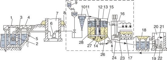
Fig. 4. Diagram of water intake from the open water body by use of a water-treatment station:
1 – well; 2 – suction strainer; 3, 8, 21 – water conduits; 4 – bridge; 5 – piles; 6, 19 – pumps;
7, 20 – 1st and 2nd elevation pumping plants; 9 – batcher; 10 – mixer; 11 – tray; 12 – central pipe; 13 – clarifier; 14 – distributing header; 15 – flocculator; 16 – gravel-sand filters;
17 – collector; 18 – underground reservoir; 19, 22 – pump for washing the sand filters;
23 – gate valve; 24 – tray; 25 – water sampling pipes; 26 – solid bottom; 27 – settler cone;
28 – ports
The 1st elevation pumping plant is provided with vacuum pumps for siphon intake from the infrabed wells and with pumps for delivery of water to the FPM (formation-pressure maintenance) system and to the main water conduit. The 1st elevation pumping plants are equipped, as a rule, with centrifugal pumps which are selected depending on the volume of injection. In this configuration, water is purified mainly by filtration through an infrabed sand pad. Secondary treatment can be carried out on the group pumping station site prior to delivery to the suction manifold of high-pressure pumps. This configuration is sufficiently efficient at a high level of infrabed waters (fig. 5).
25
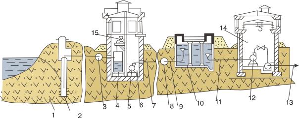
Fig. 5. Diagram of siphon water intake:
1 – sand pad; 2 – infrabed well; 3 – group siphon header; 4 – vacuum tank; 5, 12 – pumps;
6, 14 – pumping plants; 7, 8, 9, 13 – water conduits; 10 – reservoir; 11 – intake pipeline
The configuration of infrabed water treatment with a pump intake is employed at a low stand of water level (below 8 m). In this case, each infrabed well is provided with a centrifugal pump whose electric drive is mounted on the surface. These pumps make up the 1st elevation system. Over the flow line and collecting conduits, water is fed to the 2nd elevation pumping plant which comprises, in addition to pumps, an underground ferroconcrete reservoir. The 2nd elevation pumps transfer water over the delivery pipeline into the main (circular or linear) pipeline and therefrom to the group pumping stations of the oil field FPM system.
5. FRESH AND WASTE FORMATION WATER TREATMENT
FOR INJECTING INTO FORMATION
The main purpose of water treatment is attaining the desired operation qualities (ability for oil driving, viscosity, ability to provide the assigned sweep efficiency) and removal of components decreasing the injectivity index, worsening the oil quality and producing negative effect on the formation. During water treatment for injecting into the formation, such properties of it, that can bring about undesired chemical reactions in the formation, are cancelled.
26
Depending to the requirements to water to be injected and regarding the ecological and technical-and-economic conditions, the waters of surface sources are treated by two methods – with infrabed and open water intake. In case of open intake from a surface source (fig. 11), an underwater well is constructed directly in the water body where a suction strainer is located for the 1st elevation pumping plant which transfers the water cleaned for coarse mechanical admixtures to the purification plant. The basic components of the plant are: a batcher for feeding the coagulant (aluminum sulfate Al2(SO4)3 18H2O or ferrous sulfate FeSO4), a mixer for providing interaction of coagulant and water, a clarifier, and a gravel-sand filter. In the clarifier, an exchange reaction takes place with formation of flake-like components trapping the mechanical admixtures in the water. The major bulk of flakes with mechanical admixtures is separated from water directly in the clarifier, the remaining part – in the gravel-sand filters. The purified water is delivered into the underground reservoir, wherefrom it is fed by the 2nd elevation pumps to the main pipeline of the formation-pressure maintenance system. The gravel-sand filters are restored by back flow of clean water with the help of one of the 2nd elevation pumps. The duration of restoration is 10 to 15 minutes, the rate of filtration is not over 12 to 15 dm3 /cm2), which prevents washing-out of the filter proper.
Waste waters used for formation-pressure maintenance consist of 85 to 90 % of the produced formation water. The oil production industry employs both specially-developed methods for preparation of waste formation waters and methods borrowed from adjacent branches, employing large-capacity water treatment systems.
Among the most frequently used are the following methods:
–water desilting;
–water filtering through porous and other media;
–flotation;
–coalescence;
–centrifugal separation;
27
–dispergation;
–remove of admixtures by means of absorbers;
–ozonation.
For water desilting, the following technical means are used: settling reservoirs, oil traps, sand separators, and sediment ponds.
Settling reservoirs provide purification of still water according by use of encapsulated arrangement. Depending on throughput, feedstock quality, and requirements to purified water, the reservoirs of different capacity (from 200 to 5000 m3) are used with different filling and piping. The reservoirs are selected and calculated depending on the time required for water desilting (from 8 to 16 hours). The process of purification can be performed either in cycle or continuous mode. The piping of water-purification reservoirs is mainly sequential.
For fine purification of oil field waste waters from emulsified oil and hard mechanical admixtures, settlers with cartridge filters, type ОПФ-300, are employed.
Settler with the ОПФ-300 Cartridge Filters
This type of settler is intended for fine purification of oil field waste waters from emulsified oil and solid mechanical admixtures. The settler is included into a complex of equipment for purification of waster waters used in the FPM system (fig. 6).
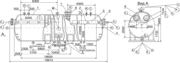
Fig. 6. Settler with the ОПФ-300 cartridge filters:
1 – reservoir; 2 – cartridge filter; 3 – cartridge filter bank; 4 – baffle tray;
5 – pure water collector; 6 – ladder; 7 – manhole; 8 – rotating device; 9 – inlet pipe
28
The settler is intended for operation in moderate and cold macroclimate areas as per GOST 15150-69. The ОПФ-300-01 filter is intended for use in macroclimate areas with moderate climate at an average temperature of the coldest fiveday period of not below 233 K (40 ºC). The minimum permissible temperature of the settler wall under pressure is 233 K (40 ºC). The climatic version is designated У1 as per GOST 15150-69.
The ОПФ-300-02 filter is intended for use in macroclimate areas with cold climate at an average temperature of the coldest five-day period from 232 to 213 K (from –40 to –60 ºC). The minimum permissible temperature under pressure is 213 K (–60 ºC).
The climatic version is designated ХЛ1 as per GOST 15150-69.
The ОПФ-300 settler comprises a standard horizontal cylindrical reservoir 1 inside which there are 16 cartridge filters 2 grouped into four cartridge-filter banks 3, four baffle support trays 4, pure water collector 5, and ladder 6. The reservoir is mounted on two saddle-like supports and is provided with manhole 7, mounting access holes, pipe unions for connection of process pipelines, installation of safety valves and I&ACS (instrumentation and automatic control system) instruments.
The reservoir is equipped with rotating device 8 for installation and removal of the manhole, load-lifting elements, and with thermal insulation attachment parts.
Operating Principle of Settler
After a preliminary coarse purification in the oil treatment facilities, waste water is fed through the distributor-pipe header and inlet pipe 9 into the internal cavity of filters, wherefrom under the action of head pressure it is filtered through foamed polyurethane into the settler cavity. Upon emulsion filtration through the foamed polyurethane, the particles of emulsified high-dispersion oil are enlarged to film size and are torn away from the filter surface by fluid flow and float up in the upper part of the settler.
29
The purified waste water is continuously taken out through the pure water collector and fed to the formation-pressure maintenance system.
The floated-up oil is taken out continuously or periodically from the settler through the oil pipe union into the trapped oil tank. Solid admixture, falling out to the reservoir bottom, is drained continuously or periodically, depending on the intensity of accumulation, together with fluid into a sludge tank.
Admission of waste water into the settler from two opposite sides allows the fluid to be distributed uniformly in the reservoir and makes it possible to increase the utilization factor of the settle volume. Location of the filters in the settler upper part decreases the height of floating of oil particles and, as a consequence, the time of fluid staying in the settler. Foamed polyurethane operates in the self-cleaning mode and does not require any regeneration which allows the filters to be used without replacement for not less than 12 months.
The settler can operate in two modes: automated and non-automated (“full filling” mode). To provide operation in the automated mode, the settler is equipped with regulators and indicators of separation level of phases “oil-water”, indicators of upper and lower fluid limit levels, actuators, and a purified water flow meter. In the “full filling” mode, the trapped oil together with gas is taken away continuously with excessive amount (up to 5 to 10 % of the settling capacity) of waste water into the trapped oil tank, wherefrom the gas is recycled or taken out to a flare, and the trapped oil is delivered to the oil treatment facilities. To facilitate adjustment of the settler to the “full filling” mode, it is recommended to install in the upper zone of the settler body 3 to 4 sampling cocks, and on the purified water and trapped oil outlet lines – flow meters.
Sediment ponds (chip catchers, emergency sumps) are intended for separating the hydrocarbon components from mechanical admixtures. The estimated time of set- tling-down is 2 days. A sediment pond is an earthwork structure with a length of up to 200 m, width across the water surface up to 40 m, and depth of 1.5 to 2.5 m and generally consists of two series-connected sections. Hydraulic seal and prevention of underground waters contamination are provided by different methods (table 1).
30