

80
.pdfАханова Н.Е. и др.
соответствовать широкому спектру требований наукоемких технологий, в том числе нанотехнологий.
В данной работе разработана структура и функциональная схема фазоизмерительной системы в нанодиапазоне. Проведено измерение реальныхперемещенийобъектоввнанодиапазоне и рассмотрены вопросы практического применения разработанных методов.
Экспериментальная установка
На основе анализа и обсуждении была разработана линейная система измерений ЛИС-01М. Данная система включает в себя:
–стабилизированный гелий-неоновый лазер;
–интерференционный оптический преобразователь;
–фотоприёмное устройство (ФПУ);
–электронно-фазометрическую систему
(ЭФС);
–блок высокочастотных генераторов (ВЧГБ);
–интерфейс связи;
–персональный компьютер;
–программное обеспечение.
ЛИС обеспечивает работу в режиме измерений перемещений Xв реальном масштабе времени путем счета фазовых циклов (ФЦ) и добавленного к ним так называемого угла фазового сдвига (УФС) Δφ:
|
∆ϕ |
|
λ |
(1), |
|
∆X = N + |
|
|
|
||
2n |
|||||
|
2π |
|
|
гдеN–фазовыециклы(N=0,1,2,3…,N),Δφ–угол фазового сдвига.
Оптическая система ЛИСпредставляет собой двулучевой модифицированный интерферометр Майкельсона. Функциональная схема ЛИС представлена на рисунке 1.
1 – лазер ЛГН 302; 2, 3- АОМ; 4, 5 – зеркала; 6, 7 – светоделительные элементы; 8 – образец с нанесённым отражающим покрытием; 9 – осциллограф; 10 – фотоприёмник;
11 – поглотитель нерабочего пучка; 12 – ЭФС; 13 – ПК и/или ноутбук Рисунок 1 – Структурно-функциональная схема ЛИС-01М
ISSN 1563-0315 |
Recent Contributions to Physics. №3 (66). 2018 |
71 |

Разработка системы измерения в нанодиапазоне
ЛИС обладает диапазоном измерений линей- |
на выходе АОМ мы получаем три пучка: нуле- |
ных перемещений 10-9-10-2м, с дискретностью |
вой,плюспервыйиминуспервый.Одинизполу- |
отсчёта 0,1 нм и быстродействием обусловлен- |
ченных пучков (например, плюс первый), падая |
ной выбранной разностной частотой. Диапазон |
на образец и отражаясь, получает информацию |
абсолютной погрешности измерений, в зависи- |
о перемещениях объекта в виде набега угла фа- |
мости от диапазона, укладывается в промежуток |
зового сдвига Δφ (информационный пучок); |
от 0,5 до 3 нм. Такие технические характеристи- |
другой пучок проходит свой оптический путь, |
ки дают возможность решать широкий спектр |
не соприкасаясь с образцом (опорный пучок). |
задач. |
Нулевой пучок поглощается дополнительным |
Эксперимент и обсуждение |
устройством (см. рис. 2). Далее информацион- |
ный и опорный пучки интерферируют, падая на |
|
|
фотоприемноеустройство(ФПУ).Последующее |
Оптический пучок, с частотой ω0 (нулевой |
выделение информационного сигнала происхо- |
пучок),проходя через первый модулятор под |
дит на разностной частоте |Ω1 – Ω2| в ФПУ. Об- |
углом Брэгга, дифрагирует на бегущей с часто- |
работка полученной информации производится |
той Ω1 дифракционной решетке, разделяясь на |
в специализированной электронно-фазометри- |
два пучка с частотами ω0 и ω0 + Ω1 (плюс первый |
ческой системе (ЭФС). ЭФС подключен к пер- |
пучок).Далеенулевойпучокпроходитчерезвто- |
сональному компьютеру. Программное обеспе- |
рой модулятор с частотой Ω2 под углом Брэгга и |
чение позволяет в режиме диалога осуществлять |
разделяется опять на два пучка с частотами ω0 |
сбор измерительных данных, их обработку и |
и ω0 – Ω2 (минус первый пучок). Таким образом, |
представление в виде, удобном для пользования. |
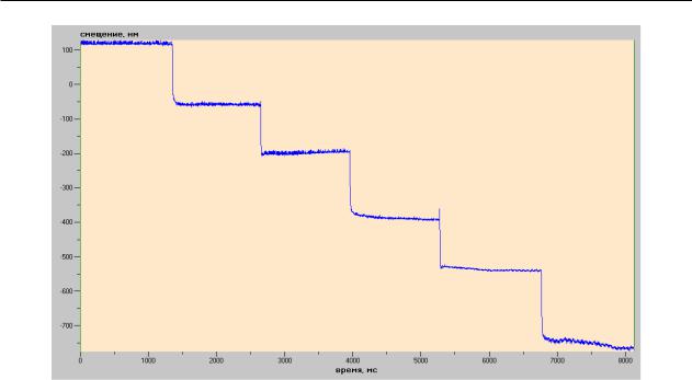
Рисунок 2 – График смещения свободного конца пьезостолбика при подаче синусоидального колебания (f ≈ 1 кГц; U= 6 В)
72 |
Вестник. Серия физическая. №3 (66). 2018 |
Аханова Н.Е. и др.
Рисунок 3 – График смещения свободного конца пъезостолбика при подаче напряжения шагом 10Вв диапазоне от 0 до 50В
Ниже приведены данные, полученные с использованием гетеродинного метода измерений смещений в нанодиапазоне. В частности, измерение колебательного смещения свободного концапьезостолбикаприподаченанегомодулирующего сигнала различной частоты и формы.
Вывод
Таким образом, разработан лазерный цифровой фазометр, работающий в широком спектральном диапазоне, предназначенные для калибровки и аттестации лазерных измерителей
линейных перемещений, а также для измерения амплитуд колебательного движения поверхности твердого тела и, обеспечивающие единство измерений в нанометровом диапазоне. Разработанная измерительная система «интерферометрфазометр», позволяет исследовать, в реальном масштабе времени, сложные пъезокерамические структуры используемых в различных устройствах в качестве актюаторов.
Благодарность. Данная работа выполнена при поддержке Министерства образования и науки Республики Казахстан в рамках гранта
AP05133211.
Литература
1 Дарзнек С.А., Желкобаев Ж., Календин В.В., Новиков Ю.А. Лазерный интерферометрический измеритель наноперемещений // Труды ИОФАН им. А.М. Прохорова, РАН. – 2006. – Том. 62. – С.14-35.
2Борн М., Вольф Э. Основы оптики. – М.: Наука, 1970. – 856 с.
3Карташев А.И., Эцин И.Ш. Методы измерения малых изменений разности фаз в интерференционных устройствах
//УФН. – 1972. – Том. 106, Вып.4. – С. 687–721.
4Галахова О.П., Колтик Е.Д., Кравченко С.А. Основы фазометрии. – М.: Энергия, 1976. – 250 с.
5 Мустель Е.Р., Парыгин В.Н. Методы модуляции и сканирования света. – М.: Наука, 1970. – 295 с. 6 Мезон У. Физическая акустика. Том VII. – М.: Мир, 1974. – 432 с.
7Корпел А. Акустооптика. – М.: Мир, 1988. – 240 с.
8Магдич Л.Н., Молчанов В.Я. Акустооптические явления и их применение. – М.: Советское радио, 1978. – 112 с.
ISSN 1563-0315 |
Recent Contributions to Physics. №3 (66). 2018 |
73 |

Разработка системы измерения в нанодиапазоне
References
1 S.A. Darznek, ZH. Zhelkobayev, V.V. Kalendin, Yu.A. Novikov, Lazernyy interferometricheskiy izmeritel’ nanoperemeshcheniy, Trudy IOFAN im. A.M. Prokhorova, RAN, 62, 15-35 (2006). (in Russ).
2 M. Born, E. Vol’f Osnovy optiki (Moskva, Nauka, 1970), 856s. (in Russ). 3 A.I. Kartashev, I.SH. Etsin, UFN, 106 (4), 687–721 (1972). (in Russ).
4 O.P. Galakhova, Ye.D. Koltik, S.A. Kravchenko Osnovy fazometrii (Moskva, Energiya, 1976), 250s. (in Russ). 5 Ye.R. Mustel’, V.N. Parygin Metody modulyatsii i skanirovaniya sveta (Moskva, Nauka, 1970), 295s. (in Russ). 6 U. Mezon Fizicheskaya akustika. Tom VII (Moskva, Mir, 1974), 432s. (in Russ).
7 A. Korpel Akustooptika (Moskva, Mir, 1988), 240s. (in Russ).
8 L.N. Magdich, V.YA. Molchanov Akustoopticheskiye yavleniya i ikh primeneniye (Moskva. Sovetskoye radio, 1978), 112s. (in Russ).
74 |
Вестник. Серия физическая. №3 (66). 2018 |

4-бөлім
БЕЙСЫЗЫҚ ФИЗИКА. РАДИОФИЗИКА
Section 4
NONLINEAR PHYSICS.
RADIOPHYSICS
Раздел 4
НЕЛИНЕЙНАЯ ФИЗИКА. РАДИОФИЗИКА
IRSTI 28.23.15
Kozhagulov Y.T.1,2, Ibraimov M.K.2,
Zhexebay D.M.1,2*, Sarmanbetov S.A.1,3
1«Kazakhstan Innovation Technologies Company» LLP, Kazakhstan, Almaty
2Al-Farabi Kazakh national university, Kazakhstan, Almaty
3Institute of Experimental and Theoretical Physics, Al-Farabi Kazakh National University, Kazakhstan, Almaty, *e-mail: zhexebay92@gmail.com
FACE DETECTION OF INTEGRAL IMAGE BY VIOLA-JONES METHOD
Research is devoted to investigate on human face detection by Viola-Jones method, the fastest and effective methods of face detection. two Haar like features have been used to determine the area of the eye, because it reduces the number of possible false positives in detecting these functions and increases the accuracy of face detection. One of them measures the difference in intensity between the eye and upper cheek area. The second function compares the intensity in the eye with intensity through the nose bridge. It is shown that these two functions can determine the facial features with different sizes pattern.
Key words: Viola-Jones method, integral image, Haar cascade, face detection, MatLab.
Кожагулов Е.Т.1,2, Ибраимов М.К.2, Жексебай Д.М.1,2*, Сарманбетов С.А.1,3
1ЖШС «Kazakhstan Innovation Technologies Company», Қазақстан, Алматы қ. 2Әл-Фараби ат. Қазақ ұлттық университеті, Қазақстан, Алматы қ.
3Эксперименттік және теориялық физика ҒЗИ, әл-Фараби ат. Қазақ ұлттық университеті, Қазақстан, Алматы қ., *e-mail: zhexebay92@gmail.com
Виола-Джонс әдісімен интегралды сурет арқылы бетті анықтау
Жұмыс бетті анықтаудың жылдам және тиімді әдістерінің бірі болып табылатын ВиолаДжонс әдісі көмегімен адам бетін детектрлеу бойынша зерттеуге арналған. Көз аймағын анықтау үшін екі Хаар функциясы пайдаланылды, себебі детектрлеу кезхінде бұл функциялардың жалған іске қосылу саны азаяды және беттерді анықтау дәлдігі артады. Олардың біреуі көз аймағы мен беттің жоғарғы бөлігі арасындағы қарқындылықтың айырмашылығын өлшейді. Екінші функция көз аймағындағы қарқындылықты мұрын көпірі қарқындылығымен салыстырады. Көрсетілгендей, бұл екі функцияның көмегімен фигураның әртүрлі өлшемді суреттегі бет кескінін анықтауға болады.
Түйін сөздер: Виола-Джонс әдісі, интегралды сурет, Хаар каскады, бетті анықтау, MatLab.
Кожагулов Е.Т.1,2, Ибраимов М.К.2, Жексебай Д.М.1,2*, Сарманбетов С.А.1,3
1ТОО «Kazakhstan Innovation Technologies Company», Казахстан, г. Алматы 2Казахский национальный университет им. аль-Фараби, Казахстан, г. Алматы
3НИИ экспериментальной и теоретической физики, Казахский национальный университет им. аль-Фараби, Казахстан, г. Алматы, *e-mail: zhexebay92@gmail.com
Интегральное изображение детектировании лиц методом Виолы-Джонса
Работа посвящена исследованию по детектированию человеческого лица с помощью метода Виолы-Джонса, который является одним из быстрых и эффективных методов обнаружения лиц. Были использованы две Хаар подобных функции для определения области глаз, так как уменьшается количество возможных ложных срабатывании этих функции при детектировании и
© 2018 Al-Farabi Kazakh National University

Kozhagulov Y.T. et al.
увеличивается точность определения лиц. Одна из них измеряет разницу в интенсивности между областью глаз и верхней щеки. Вторая функция сравнивает интенсивности в области глаз с интенсивностью через мост носа. Показано, что с помощью этих двух функции можно определить черты лица с разными размерами рисунка.
Ключевые слова: метод Виолы-Джонса, интегральное изображение, Хаар каскад, обнаружение лиц, MatLab.
Introduction
Face detection and recognition is an important task of machine and computer vision. There are many face detection algorithms [1-5]. One of the fastest and effective methods of face detection is a Viola-Jones method [6, 7]. This method is most clearly different from previous approaches by its ability to detect faces very quickly. The Viola-Jones algorithm of a certain threshold value provides fast detection and high accuracy. Average detection accuracy is 97.41% as described in research [8]. A large number of persons present in the image does not affect the calculation time, as well as detection speed. Calculation time increases when the image has a big size and high density.
Viola-Jones method consists of three basic object detection algorithms. The first is a new image representation in the form of an integral image that allows to evaluate objects very quickly. This algorithm does not work directly with the intensity of the image compared with the research [9]. But like these authors a set of features are applied that are reminiscent of the Haar basic functions. The integral image can be calculated through applying the multiple operations per pixel. Thereafter, Haar like function can be calculated at any scale or location in real time.
The second algorithm – a method of constructing the classifier by selecting a small number of important features applying AdaBoost [10]. In any image subband total number of Haarlike objects is very large, much larger than the number of pixels. To provide fast classification, the learning process should exclude the vast majority of the available functions and focus on a small set of
critical functions. As a result each stage acceleration process that chooses a new class of weak, can be considered as feature selection process. AdaBoost learning algorithm provides an efficient and powerful assessment generalizations efficiency.
The third important algorithm is a method of combining successively more complex classifiers into the cascade structure that rapidly increases the speed detector, focusing on advanced areas of the image. The concept of the focus of attention is that often you can quickly determine where the object may occur in the image [11-13]. A more complex treatment is reserved only for these advanced areas.
Theoretical and experimental research backgrounds
Viola-Jones method applies Haar like features to identify the facial features. In order to reduce the calculation time of these functions the integral image representation is applied [6, 7, 14, 15]. Integral image representation – is the matrix, the same size of the original image. Each matrix element comprises sum of the intensities of all pixels located to the left of and above the element. For integral image matrix elements calculation the following formula is applied:
|
i x, j y |
|
L x, y |
I i, j |
(1) |
i 0, j 0
where I i, j – the brightness of the source image
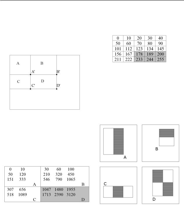
pixel. Figure 1 shows matrix of the starting and integral image.
Figure 1 – Integral image
ISSN 1563-0315 |
Recent Contributions to Physics. №3 (66). 2018 |
77 |
Face detection of integral image by viola-jones method
By applying the integral images any rectangular amount can be calculated in four references to the array (Figure 2). It is clear that the difference between the two rectangular sums can be calculated in the eight references. Since the functions described above with two rectangles connected with adjacent rectangular sums, they can be calculated in six references to arrays.
Figure 2 – Calculation of field D total intensity
The field D total intensity is calculated by the following formula:
|
|
|
|
|
(2) |
D D |
A |
B |
C |
According to this formula we will calculate a dark zone of integral image (Figure 3).
Figure 3 – Calculation of the integral image total intensity
In this figure the area A consists of six (pixels), respectively equal to the sum of the intensity field 333 ( A 333 ). Other areas are: B' = 1065. C' =
1089 and D' = 3120. The total intensity of the field D = D' + A– (B' + C') = 3120 + 333 – 1065 – 1089= 1299. We check the correctness of the formula applying the original image (Figure 4):
Figure 4 – Original image
D 178 189 200 233 244 255 1299 that proves the correctness of the formula (2).
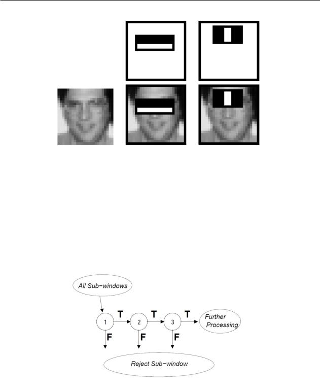
Face detection based Haar-like features (Figure 5). To find the location of a human face the eyes need to calculate the function shown in Figure 5 (B). This function measures the difference in intensity between the eyes and the through upper cheek area, because the eye area is often darker in comparison with the cheeks.
Figure 5 – Haar Features
Scan all Haar primitives for one picture can be time consuming. Therefore, through applying the AdaBoost classifier, you can select the needed primitives (Figure 6) [6, 7].
78 |
Хабаршы. Физика сериясы. №3 (66). 2018 |
Kozhagulov Y.T. et al.
Figure 6 – The first and second functions are selected by applying AdaBoost
Classifiers cascade algorithm provides improved detection efficiency and significantly reduces the calculation time. The critical understanding is that they can be built smaller and therefore more effective, increasing classifiers rejecting many of the negative auxiliary window when it detects almost all positive specimens.
Simpler classifiers are applied to reject most of the sub-window, before more complex classifiers
are designed to achieve low levels of false positives. The detection process general form is a process of degeneration of the decision tree, that called «cascading» (Figure 7). A first classifier positive result starts the evaluation of a second classifier that has also been adjusted to achieve very high detection rates. Second classifier positive result from the second classifier triggers the third classifier, etc. A negative result at any point leads to the immediate window rejection.
Figure 7 – Schematic drawing of the detection cascade
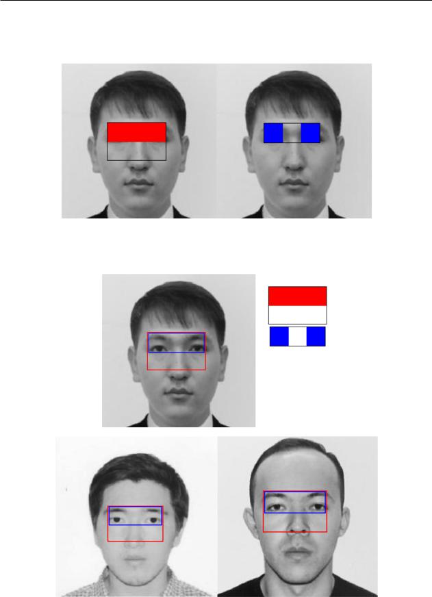
Research result
We applied two Haar like features to define facial features (Figure 8). Because the first function measures the difference in intensity between the area of the eyes and the upper cheek area, as the eye
area is often darker in comparison with the cheeks. The second function compares the intensity of the eye areas with intensity through the bridge of the nose.
These two features can define the scope of the human eye. Applying one of them can not accurately
ISSN 1563-0315 |
Recent Contributions to Physics. №3 (66). 2018 |
79 |
Face detection of integral image by viola-jones method
determine the area of the face. Therefore, to increase the accuracy of the two functions were applied.
Figure 9 shows the determination result of human face by applying Haar like functions.
(a) (b)
Figure 8 – The first (a) and second (b) Haar like function to detect faces
(a)
|
(b) |
(c) |
|
Figure 9 – Human face detection |
|
80 |
Хабаршы. Физика сериясы. №3 (66). 2018 |
|