1326
.pdfmal extent and they will focus to reduced mobility people and if it will necessary they will rescue people injured by fire.
The fire and rescue units cannot successfully determine fire of railway sets in tunnel. The situation in tunnel after ignition of fire is hazardous for trespassing fire fighters. Implemented experiments in tunnels showed the temperatures increase to extremely value inside tunnel in during of fire, higher than 1000 °C. Development of fire is affected by many factors. The main factors are parameters of railway tunnel that is meant its length, profile, slope, building design and equipment. In next during of fire is affected by position of rail set in tunnel, climate situation, mainly air temperature, speed and direction. The intervention is affected by position of railway tunnel with respect of ambient buildings, approach, the number of fire fighters and their equipments. The intervention will affected by factors field with personal or cargo transportation and type of locomotive drive.
In field of intervention in railway tunnels is possible expecting:
−Smoke filling tunnel and low visibility
−High temperatures of area inside tunnel and radiation heat
−Danger of injury by electricity
−Overcoming long distances on railway lines
−A cramped space in place of staying the railway set
−Physical demanding transport of equipments on the intervention place
−Problems with transport of water
−Problems with ensure of connection between intervention units inside the tunnel and between portals.
The conditions are dangerous in tunnel after ignition of fire for fire fighters, mainly with respect to value of temperature in area and level of smoke filled area. This risk is related with during of fire in tunnel with a fact, the arriving time of rescue units is in most of railway tunnels in high value. The fire fighters use cover suit in during of intervention. This suit is tested for these parameters (Table 1):
Table 1
Requirement cover suit
Condition |
Time of expositions |
Temperature |
Heat flow density |
Normal |
8 hod |
40 °C |
1 kW.m–2 |
Dangerous |
5 min |
250 °C |
1,75 kW.m–2 |
Emergency |
10 s |
800 °C |
40 kW.m–2 |
The fire fighters can safely intervene in area with respect to these values where the temperature is not higher than 250 °C. These temperatures are attained in conditions of fire in distance more than 50 m from position of fire. It is not possible determine fire with equipment which is used by fire fighters, mainly with respect to parameters used hose nozzles.
3. Probability of fire ignition in tunnel
The statistic data was used for execution of probability analysis of fire ignition in railway tunnel. These and next data for calculating probability of fire ignition in railway tunnel in the presence of railway sets inside of the tunnel was gained from specialized department of Czech railways company in Czech republic.
As emerged from the available data, the recorded fires in railway tunnels were in motion without the present of railway sets inside the tunnel, therefore was used data about fires inside
121
Стр. 121 |
ЭБ ПНИПУ (elib.pstu.ru) |
the railway vehicles it means in railway sets of personal transport and cargo transport. With respect to the fact the operating rules of transportation by railway are not access stopping of railway sets inside the tunnel. It was found number of emergencies on railway lines (fatal accidents), which leads to the stopping of railway sets also inside the tunnel.
4. Description Methodics of probability calculating
In field of gained data, the probability analyse researched phenomenon, which include ignition of fire in railway tunnel, ignition of fire in railway set, ignition crisis situation on railway, based on assumption the random value as number of fires and emergencies and their ignition on railway line in during of day has Posisson’s probability distribution.
The Poisson’s distribution has generally random variables, which describe frequency of phenomenon with those properties:
1.Phenomenon will realized in defined time interval or place (or will not realized), the phenomenon will independent what was happen in another time or place
2.For every moment is probability of phenomenon in small time interval the same (it is relates also the phenomenon in small area)
3.There is not exists the case there was realized two phenomenon in the exactly same time moment or on the same place.
The random variable exactly satisfies these properties, which was realized by calculat-
ing.
Probability function of Poisson’s distribution defines this formula:
p(x) = |
λ x |
e−λ |
in the interval, or |
p(x) = |
(l λ )x |
e−l λ |
in the length l (in l-multiple of |
|
x! |
|
|
|
x! |
|
|
length defined interval). The parameter λ describe average number of occurrence the researched phenomenon in defined interval of length.
There are data which was selected from year 2004 until 2008 related completed number of fires in railway sets for individual years, in next it is data related with emergencies on railways for calculating of the unknown parameter Poisson’s distribution. These data were related in ratio between all-length of tunnels with all-length of railways in Czech Republic. The number of trains per day was respected in calculating. The probability of ignition a fire of train in a tunnel with final length and probability ignition of emergency in tunnel of final length in specified time interval was defined from this calculation. The probability of fire in a train after stopping inside tunnel of final length in emergency which will get to stop the train is possible to calculate by both entries.
The number of railway tunnels, their length and also length of railway lines in individual years for which was realized statistic analyse of fires and emergencies is showed in Table 2.
|
|
|
|
|
|
Table 2 |
Parameters of railway tunnels and railway lines |
|
|
||||
|
|
|
|
|
|
|
Years |
2008 |
2007 |
2006 |
|
2005 |
2004 |
Number of railway tunnels |
157 |
152 |
154 |
|
152 |
152 |
All-length of railway tunnels [m] |
45750 |
40 387 |
38 383 |
|
38 155 |
35 157 |
All-length of railway lines [km] |
9430 |
9 487 |
9 496 |
|
9 513 |
9 511 |
122
Стр. 122 |
ЭБ ПНИПУ (elib.pstu.ru) |

The railway sets are moving on the railway lines in common traffic. In the Table 3 is showed number of railway sets, whose are moving in individual days in period of last quarter the year 2008. Showed data was provided by railway dispatching of Czech Railways.
|
|
|
|
|
|
|
|
Table 3 |
|
The number dispatched railway sets in during of the day |
|
||||||
|
|
|
|
|
|
|
|
|
Day |
Mon |
Tue |
Wed |
Thu |
Fri |
Sut |
Sun |
Average per day |
Number of trains |
7942 |
7930 |
7930 |
7930 |
7967 |
6079 |
5956 |
7390,57 |
The probability analyse of fire ignition and emergency ignition is accomplish with respect to statistic data and showed evaluation and railway tunnels with final length between 500 and 4000 meters.
5. Probability of ignition the fire on railway set
The data for evaluating of probability ignition the fire on railway set was used data in Table 4.
|
|
|
|
|
Table 4 |
|
The number of fires on vehicles in railway set |
|
|||
|
|
|
|
|
|
Years |
Locomotive |
Coach |
Cargo |
Other |
Total |
2004 |
65 |
15 |
17 |
1 |
98 |
2005 |
56 |
8 |
28 |
0 |
92 |
2006 |
44 |
19 |
18 |
0 |
81 |
2007 |
73 |
13 |
28 |
0 |
114 |
½ 2008 |
25 |
2 |
16 |
0 |
43 |
Total |
263 |
57 |
107 |
1 |
428 |
Average data, whose are on the base of showed data, of fires on railway vehicles the railway sets in moving through the tunnels per year are showed in Table 5. Average numbers of fires per first year in tunnel is calculated from year 2004–2008 on base of all-length tunnels in years 2008. The assumption of occurrence the fires are regular for all length of railway line.
Table 5
Average number of fires on vehicles of railway sets in railway tunnels per year
Locomotive |
Coach |
Cargo |
Other |
Total |
0,248803 |
0,053923 |
0,101224 |
0,000946 |
0,404896 |
In next the probability of individual number of fires on vehicles of railway sets in during of moving through the tunnels was calculated on base of all-length tunnel per year. In common traffic the moving of railway set in tunnel is field on organization of transportation on rails. The probability of ignition fire in coach and cargo vehicles of specified railway set in moving through the final length tunnel per year are showed in Table 6.
123
Стр. 123 |
ЭБ ПНИПУ (elib.pstu.ru) |

Table 6
The probability of ignition fire on coach and cargo in specified one railway set moved through the tunnel with final length per year
Coach |
|
Number of fires |
|
|
1 |
2 |
1 and more |
||
|
||||
Length of tunnel 500 m |
9,03E-08 |
4,08E-15 |
9,03E-08 |
|
1000 m |
1,81E-07 |
1,63E-14 |
1,81E-07 |
|
2500 m |
4,52E-07 |
1,02E-13 |
4,52E-07 |
|
4000 m |
7,23E-07 |
2,61E-13 |
7,23E-07 |
|
Cargo |
1 |
2 |
1 and more |
|
Length of tunnel 500 m |
1,70E-07 |
1,44E-14 |
1,70E-07 |
|
1000 m |
3,39E-07 |
5,75E-14 |
3,39E-07 |
|
2500 m |
8,48E-07 |
3,59E-13 |
8,48E-07 |
|
4000 m |
1,36E-06 |
9,20E-13 |
1,36E-06 |
The probability of ignition fire on vehicle of one specified railway set moved through the tunnel with length between 500 m – 4000 m is in range from 1,36×10⁻⁶ to 9,03×10⁻⁸ per year.
6. Probability of ignition emergency on railway line
The probability of ignition emergency on railway line is analysed on base of data, which was publish in statistic yearbook of Czech Railways. Emergencies on railway sets, which becomes on railway lines are showed in Table 7. The precondition of probability analyse is every emergency will lead to stop the railway set.
|
|
|
|
|
|
Table 7 |
|
Number of emergencies on railway lines |
|
|
|||
|
|
|
|
2006 |
|
|
Years |
|
2008 |
2007 |
2005 |
2004 |
|
Number of emergencies |
|
1129 |
1616 |
2503 |
2600 |
2503 |
The average number of emergencies in railway tunnels per year is showed in Table 8. Average number of emergencies in tunnel per 1 year is calculated from year 2004 to 2008 on length tunnel in 2008. In next the regular occurrence of emergencies is assumed for all-length of railway line.
Table 8
Average number of emergencies in railway tunnels per year
Emergencies |
Total |
Number |
8,486957 |
The probability for individual numbers of emergencies on railway set moved through the tunnel per year was completed by accomplished calculation. The probability of ignition emergencies on one specified railway set moved through the tunnel per year is showed in Table 9.
124
Стр. 124 |
ЭБ ПНИПУ (elib.pstu.ru) |
Table 9
Probability of ignition emergency on one specified railway set moved through the tunnel per year
Length of tunnel |
|
Number of emergencies |
|
||
1 |
|
2 |
|
1 and more |
|
|
|
|
|||
500 m |
1,60E-05 |
|
1,28E-10 |
|
1,60E-05 |
1000 m |
3,19E-05 |
|
5,10E-10 |
|
3,19E-05 |
2500 m |
7,99E-05 |
|
3,19E-09 |
|
7,99E-05 |
4000 m |
1,28E-04 |
|
8,16E-09 |
|
1,28E-04 |
The probability of ignition emergency with respect to the length of railway tunnel which will lead to stop the railway set in tunnel is possible define in ration 1,6×10⁻⁵ – 1,28×10⁻⁴ per year.
7. Probability ignition fire in railway set after stopping inside a tunnel
The ignition of fire railway set inside a tunnel is depend on ignition fire on coach or cargo vehicle of railway set and at the same time ignition emergency, which will lead to stop railway set inside the tunnel. The failure of railway set will lead to stop inside the tunnel and the fire will develop with impact on surroundings and person, whose are in tunnel. The probability of stopping coach railway set in tunnel from 500m to 4000m with respect to showed value is in ration from 9,25×10⁻¹¹ to 1,44×10⁻¹² per year. The probability of stopping burning
cargo railway set inside the tunnel in length from 500m to 4000m is from 1,74×10⁻¹⁰ to 2,72×10⁻¹² per year.
Получено 10.10.2013
Стр. 125 |
ЭБ ПНИПУ (elib.pstu.ru) |
УДК 620.179
М.Н. Апталаев
Пермский национальный исследовательский политехнический университет
МЕТОД КАНАЛЬНОЙ ПРОКЛАДКИ ТРУБОПРОВОДОВ
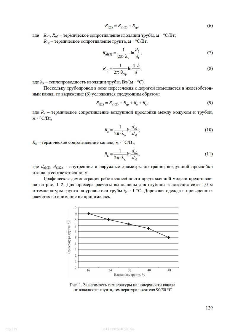
Рассмотрены основные особенности канального метода прокладки инженерных коммуникаций. Представлена математическая модель для количественной оценки влияния трубопровода на тепловой режим грунтового массива. Рассмотрена зависимость температуры произвольной точки грунтового массива от плотности и влажности грунта.
Ключевые слова: инженерные коммуникации, метод канальной прокладки, математическая модель, тепловой режим грунтового массива.
M.N. Aptalaev
Perm National Research Polytechnic University
METHOD CHANNEL LAYING OF PIPELINES
In article describe the main features of the channel method of installation engineering services. A mathematical model for the quantify assessment of the impact of pipeline on the thermal regime of the soil mass is offered. The dependence of the temperature of an arbitrary point of the soil mass from density and moisture of the soil is considered.
Keywords: utilities, channel construction method, mathematical model, thermal regime of the soil mass.
Инженерные коммуникации, расположенные под проезжей частью уличнодорожной сети (УДС) города, оказывают значительное влияние на условия эксплуатации транспортных объектов. Можно выделить наиболее значимые факторы данных изменений:
–прорывы коммуникаций;
–утечки носителя из трубопровода;
–качество засыпки траншей после ремонтно-строительных работ.
Исключить пересечение подземных инженерных коммуникаций с УДС города практически невозможно даже на этапе нового строительства. Поэтому разработка рекомендаций по размещению трубопроводов в зонах пересечения с улицами и дорогами, основанных на анализе их взаимного влияния, является важной задачей.
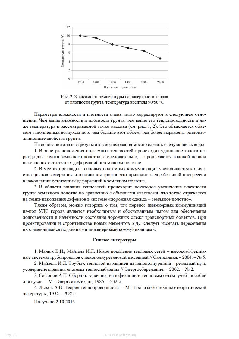
Вокруг тепловых сетей формируется температурно-влажный пояс. Связанные с этим потери тепла сопряжены не только с перерасходом теплоносителя, но и с изменением условий работы системы «земляное полотно – дорожная одежда». Кроме прямого воздействия, теплопотери также обратно влияют на саму коммуникационную сеть.
По данным разных источников, протяженность теплопроводов подземной и надземной прокладки в Российской Федерации составляет более 250 тыс. км. Не менее 85 % об-
126
Стр. 126 |
ЭБ ПНИПУ (elib.pstu.ru) |
щей протяженности составляют тепловые сети подземной прокладки. При этом для 80 % трубопроводов тепловых сетей превышен срок безаварийной эксплуатации, а более 30 % из них физически устарели и требуют капитального ремонта либо замены [1].
Основным способом строительства тепловых сетей является подземная канальная прокладка (до 84 % от общего количества). Данный вид прокладки имеет ряд неоспоримых преимуществ:
–каналы предохраняют теплопроводы от воздействия грунтовых, атмосферных
ипаводковых вод;
–трубопроводы в них укладывают на подвижные и неподвижные опоры, при этом обеспечивается организованное тепловое удлинение;
–канальной прокладкой трубопроводов достигается быстрый доступ к трубам при ремонтах и осмотрах;
–в канальных прокладках давление грунта передается на строительные конструкции канала. Таким образом, трубопровод и его изоляционная конструкция не испытывают напряжений от давления грунта и внешних нагрузок на него;
–каналы предотвращают выброс теплоносителя на поверхность земли при разрыве трубопровода.
Также имеется ряд недостатков:
–стоимость строительства в зависимости от диаметра выше на 10–50 % по сравнению с бесканальным методом;
–сроки строительства выше в 2–3 раза по сравнению с бесканальным. Бесканальная прокладка с применением предварительно изолированных труб
применяется там, где технически невозможно или экономически нецелесообразно устройство дренажных систем для предотвращения затопления каналов грунтовыми водами и атмосферными осадками. На данный момент лишь 6 % от общего объема тепловых сетей выполнено по данной технологии [1, 2].
Для обеспечения контроля и своевременного устранения дефектов, при строительстве подземных трубопроводов требуется предусмотреть наличие средств дистанционного контроля за состоянием труб.
Учитывая полное отсутствие обоснования по размещению теплотрасс при пересечении с дорожными объектами, была предпринята попытка по исследованию особенностей формирования водно-теплового режима земляного полотна в зоне их пересечения с УДС города.
Подземные теплопроводы представляют собой внутригрунтовый искусственный тепловой источник, расположенный обычно на глубине 2–2,5 м от поверхности дорожной одежды. Незначительная глубина заложения обоснована наличием защитного железобетонного канала. Такое решение также предполагает удобство ремонта без вскрытия дорожного полотна.
При традиционных подходах к описанию и объяснению закономерностей воднотеплового режима земляного полотна (труды И.А. Золотаря, Н.А. Пузакова, В.М. Сиденко, А.Я. Тулаева, В.И. Рувинского, В.П. Носова, Е.И. Шелопаева, А.Я. Ярмолинского и многих других) исходят, прежде всего, из учета динамики тех или иных климатических факторов и конструктивных особенностей земляного полотна и дорожной одежды. Присутствие источника излучения теплового потока непосредственно в грунтовой среде не рассматривалось, хотя его наличие вблизи активной зоны земляного полотна заметно изменяет температурно-влажностный баланс.
127
Стр. 127 |
ЭБ ПНИПУ (elib.pstu.ru) |

Для количественной оценки влияния канального теплопровода на ход сезонного промерзания и оттаивания, влагонакопления, разуплотнения и других процессов необходимо, прежде всего, реализовать изотермическое моделирование земляного полотна.
Первым этапом при решении данной задачи становится получение и апробация математического выражения для расчета температур от излучаемого через трубопровод теплового потока.
Искомое выражение базируется на известном уравнении теплопроводности для полого цилиндра (трубы) произвольной длины [3]:
|
|
|
|
|
|
|
|
|
2πL |
|
|
(t1 |
− t2 ), |
|
|
Q = λ |
|
|
(1) |
||||
|
d2 |
|
|||||
|
|
|
|
|
|
|
|
h |
|
|
|
|
|
|
|
d |
|
|
|
||||
|
1 |
|
|
|
|
|
|
где Q – количество тепла, проходящего за единицу времени, Вт; λ – теплопроводность, Вт/(м · °С);
L – длина полого цилиндра, м;
d1, d2 – внутренний и внешний диаметры трубы соответственно, м;
t1 – t2 – температура между противоположными поверхностями цилиндра, °С. Развернутое выражение для определения температуры в произвольной точке грун-
тового массива вокруг двухтрубного теплопровода, полученное преобразованием уравнения Ламе и Клапейрона, предложено А.П. Сафоновым [4]:
t = t0 + |
q |
ln |
x2 + ( y + h)2 |
+ |
q |
ln |
(x − b)2 + ( y + h)2 |
|
2π λгр |
x2 + ( y − h)2 |
2π λгр |
(x − b)2 + ( y − h)2 , |
|||||
|
1 |
|
|
|
2 |
|
|
|
где t0 – температура грунта на глубине оси теплопровода, °С;
q1, q2 – удельные тепловые потери первой и второй труб соответственно, Вт/м; λгр – теплопроводность грунта, Вт/(м · °С);
х и y – координаты расположения точки в грунте, м;
h – глубина заложения оси теплопровода от поверхности земли, м; b – горизонтальное расстояние между осями труб, м.
q1 = (τ1 − t0 )R2 − (τ2 − t0 )R0 , R1 R2 − R02
q2 = (τ2 − t0 )R2 − (τ1 − t0 )R0 , R1 R2 − R02
(2)
(3)
(4)
где τ1, τ2 – температура теплоносителя в первой и второй трубах соответственно, °С; R0 – условное дополнительное термическое сопротивление, учитывающее взаим-
ное влияние первой и второй труб, м · °С/Вт;
R1, R2 – суммарное термическое сопротивление первой и второй труб соответственно, м · °С/Вт.
R0 = |
1 |
|
1+ |
|
2h 2 |
|
|
ln |
|
b , |
(5) |
||
2π λгр |
128
Стр. 128 |
ЭБ ПНИПУ (elib.pstu.ru) |