755
.pdf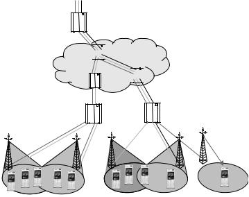
240 |
3G Evolution: HSPA and LTE for Mobile Broadband |
MBMS content
BM-SC
Outer coding


 GGSN
GGSN
Core network
SGSN 


RNC
NodeB
Cell 1 |
Cell 2 |
Cell 3 |
Cell 4 |
Cell 5 |
Figure 11.1 Example of MBMS services. Different services are provided in different areas using broadcast in cells 1-4. In cell 5, unicast is used as there is only single user subscribing to the MBMS service.
To a large extent, MBMS affects mainly the nodes above the radio-access network. A new node, the Broadcast Multicast Service Center (BM-SC), illustrated in Figure 11.1, is introduced. The BM-SC is responsible for authorization and authentication of content provider, charging, and the overall configuration of the data flow through the core network. It is also responsible for application-level coding as discussed below.
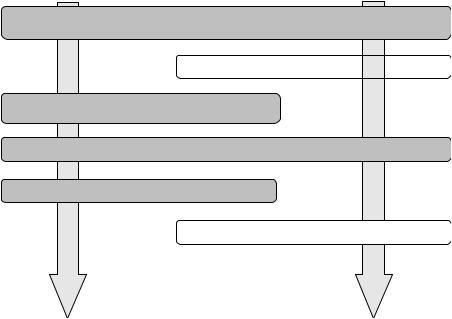
As the focus of this book is on the radio-access network, the procedures for MBMS will only be briefly described. In Figure 11.2, typical phases during an MBMS session are illustrated. First, the service is announced. In case of broadcast, there are no further actions required by the user; the user simply ‘tunes’ to the channel of interest. In case of multicast, a request to join the session has to be sent to become member of the corresponding MBMS service group and, as such, receive the data. Before the MBMS transmission can start, the BM-SC sends a session-start request to the core network, which allocates the necessary internal resources and request the appropriate radio resources from the radio-access network. All terminals of the corresponding MBMS service group are also notified that content delivery from the service will start. Data will then be transmitted from the content server to the end users. When the data transmission stops, the server will send a session-stop notification. Also, users who want to leave an MBMS multicast service can request to be removed from the MBMS service group.
MBMS |
|
|
|
|
241 |
||||||
Server |
MBMS phases |
|
Client (UE) |
||||||||
Announces the service |
Service announcement |
Notified about the service |
|||||||||
and how to access it |
|||||||||||
|
|
|
|
|
|
|
|
|
|
||
|
|
|
|
|
|
|
|
|
|||
|
|
|
|
|
|
|
|
|
|
||
|
|
Joining |
|
|
Decides to |
activate |
the service |
|
|||
|
|
|
|
|
|
|
|
|
|
|
|
Starts the session |
Session start |
|
|
|
|
|
|
||||
|
|
|
|
|
|
||||||
MBMS notification |
|
|
|
|
|
|
|||||
|
|
|
|
|
|
|
|||||
Transmits data |
Data transfer |
|
Receives data |
||||||||
Stops the service |
Session stop |
|
|
|
|
|
|
||||
|
|
|
|
|
|
|
|
|
|||
|
|
Leaving |
|
|
Terminates |
the service |
|
||||
|
|
|
|
|
|
|
|
|
|
|
|
Figure 11.2 Example of typical phases during an MBMS session. The dashed phases are only used in case of multicast and not for broadcast.
One of the main benefits brought by MBMS is the resource savings in the network as a single stream of data may serve multiple users. This is seen in Figure 11.1, where three different services are offered in different areas. From the BM-SC, data streams are fed to each of the NodeBs involved in providing the MBMS services. As seen in the figure, the data stream intended for multiple users is not split until necessary. For example, there is only a single stream of data sent to all the users in cell 3. This is in contrast to previous releases of UTRAN, where one stream per user has to be configured throughout both the core network and the radio access network.
In the following, the principles behind MBMS in the radio access network and their introduction into WCDMA will be discussed. The focus is on point- to-multipoint transmission as this requires some new features in the radio interface. Point-to-point transmission uses either dedicated channels or HSDSCH and are, from a radio-interface perspective, not different from any other transmission.
A description of MBMS from a specification perspective is found in [102] and the references therein.

244 |
3G Evolution: HSPA and LTE for Mobile Broadband |
signal rather than treat it as interference. However, as WCDMA uses cell-specific scrambling of all data transmissions, the soft combining needs to be performed by the appropriate UE processing. This processing is also responsible for suppressing the interference caused by (non-MBMS) transmission activity in the neighboring cells. To perform soft combining, the physical channels to be combined should be identical. For MBMS, this implies the same physical channel content and structure should be used on the radio links that are soft combined.
Selection combining, on the other hand, decodes the signal received from each cell individually and for each TTI selects one (if any) of the correctly decoded data blocks for further processing by higher layers. From a performance perspective, soft combining is preferable as it provides not only diversity gains, but also a power gain as the received power from multiple cells is exploited. Relative to selection combining, the gain is in the order of 2–3 dB [80].
The reason for supporting two different combining strategies is to handle different levels of asynchronism in the network. For soft combining, the soft bits from each radio link have to be buffered until the whole TTI is received from all involved radio links and the soft combining can start, while for selection combining, each radio link is decoded separately and it is sufficient to buffer the decoded information bits from each link. Hence, for a large degree of asynchronism, selection combining requires less buffering in the UE at the cost of an increase in Turbo decoding processing and loss of performance. The UE is informed about the level of synchronism and can, based upon this information and its internal implementation, decide to use any combination scheme as long as it fulfills the minimum performance requirements mandated by the specifications. With similar buffering requirements as for a 3.6 Mbit/s HSDPA terminal, which is the basis for the definition of the UE MBMS requirements, soft combining is possible provided the transmissions from the different cells are synchronized within approximately 80 ms, which is likely to be realistic in most situations.
As mentioned above, the UE capabilities are set assuming similar buffering requirements as for a 3.6 Mbit/s HSDPA terminal. This result in certain limitations in the number of radio links a terminal is required to be able to soft combine for different TTI values and different data rates. This is illustrated in Table 11.1, from which it is also seen that all MBMS-capable UEs can support data rates up to 256 kbit/s. It is worth noting that there is a single MBMS UE capability – either the UE supports MBMS or not. As network planning has to be done assuming a certain set of UE capabilities in terms of soft combining, etc., exceeding these capabilities cannot be exploited by the operator. The end user may of course benefit from a more advanced terminal, for example through the possibility for receiving multiple services simultaneously.
MBMS |
245 |
Table 11.1 Requirements on UE processing for MBMS reception [99].
Data rate (on MTCH) |
Soft combining |
|
|
Selection combining |
|
|
|
|
|
|
|
|
|
|
|
|
|
|
Maximum number of RLs |
TTI |
|
Maximum number of RLs |
TTI |
256 kbit/s |
3 |
40 |
2 |
40 |
|
|
≤2 |
80 |
1 |
80 |
|
128 kbit/s |
≤3 |
80 |
3 |
40 |
|
|
|
|
2 |
80 |
|
≤64 kbit/s |
≤3 |
|
1 |
80 |
|
80 |
|
≤3 |
80 |
||
11.1.2Application-level coding
Many end-user applications require very low error probabilities, in the order of 10−6. Providing these low error probabilities on the transport channel level can power-wise be quite costly. In point-to-point communications, some form of (hybrid) ARQ mechanism is therefore used to retransmit erroneous packets. HSDPA, for example, uses both a hybrid-ARQ mechanism (see Chapter 9) and RLC retransmissions. In addition, the TCP protocol itself also performs retransmissions to provide virtually error-free packet delivery. However, as previously discussed, broadcast typically cannot rely on feedback, and, consequently, alternative strategies need to be used. For MBMS, application-level forward errorcorrecting coding is used to address this problem. The application-level coding resides in the BM-SC and is thus not part of the radio-access network, but is nevertheless highly relevant for a discussion of the radio-access-network design for support of MBMS. With application-level coding, the system can operate at a transport-channel block-error rate in the order of 1–10% instead of fractions of a percent, which significantly lowers transmit power requirement. As the application-level coding resides in the BM-SC, it is also effective against occasional packet losses in the transport network, for example due to temporary overload conditions.
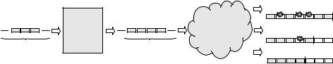
Systematic Raptor codes [63] have been selected for the application-level coding in MBMS [105], operating on packets of constant size (48–512 bytes). Raptor codes belongs to a class of Fountain codes, and as many encoding packets as needed can be generated on-the-fly from the source data. For the decoder to be able to reconstruct the information, it only needs to receive sufficiently many coded packets. It does not matter which coded packets it received, in what order they are received, or if certain packets were lost (Figure 11.5).
In addition to provide additional protection against packet losses and to reduce the required transmission power, the use of application-level coding also simplifies the
MBMS |
|
|
|
|
|
|
|
|
|
|
|
|
|
|
|
|
|
247 |
|||||||
|
|
|
|
|
|
|
|
|
|
From core network |
|
|
|
|
|
|
|
|
|||||||
|
|
|
|
|
|
|
|
|
Point-to-point |
|
|
|
|
|
|
|
Point-to-multipoint |
|
|
|
|
||||
|
|
|
|
|
|
|
|
|
|
|
|
|
|
|
|
|
|
|
|
||||||
|
|
|
|
|
|
|
|
|
|
|
|
|
|
|
|
|
|||||||||
Radio |
|
|
|
|
|
|
|
|
radio bearers |
|
|
|
|
|
|
|
radio bearers |
|
|||||||
bearers |
|
|
|
|
|
|
|
|
|
|
|
|
|
|
|
|
|
|
|
|
|
|
|
|
|
|
|
|
|
|
|
|
|
|
|
|
|
|
|
|
|
|
|
|
|
|
|
|
|
|
|
|
|
|
|
|
|
|
|
|
|
|
|
|
|
|
|
|
|
|
|
|
|
|
|
|
|
|
|
|
|
RLC |
|
|
|
|
RLC |
|
|
|
|
|
RLC |
|
|
||||||||
|
|
|
|
RLC |
|
|
|
|
|
|
|
|
|
|
|
||||||||||
Logical |
DTCH |
|
|
RLC |
|
|
|
|
|
|
|
|
|
|
|
|
|
|
|
|
|
|
|||
|
|
|
|
|
|
|
|
|
|
|
|
|
|
|
|
|
|
|
|
|
|
|
|
||
|
|
|
|
|
|
|
MTCH |
MTCH |
|
|
|
||||||||||||||
channels |
|
|
|
|
|
|
|
|
|
|
|
|
|
|
|
|
|
|
|
|
|
|
|
|
|
|
|
|
|
MAC |
|
|
|
|
MAC |
|
|
|
|
|
MAC |
|
|
||||||||
|
|
|
|
MAC |
|
|
|
|
MAC |
|
|
|
|
|
|
|
|||||||||
Transport |
HS-DSCH |
|
|
MAC |
|
|
|
|
MAC |
|
|
|
|
|
|
|
|
|
|
||||||
|
|
|
|
|
|
|
|
|
|
|
|
|
|
|
|
|
|
|
|
|
|
|
|||
|
|
|
|
|
|
|
FACH |
|
|
|
|
|
FACH |
||||||||||||
channels |
|
|
|
|
|
|
|
|
|
|
|
|
|
|
|
|
|
|
|
|
|
|
|
|
|
|
|
|
|
|
|
|
|
|
|
|
|
|
|
|
|
|
|
|
|
|
|
|
|
|
|
|
|
|
|
|
L1 |
|
|
|
|
L1 |
|
|
L1 |
||||||||||||
|
|
|
|
L1 |
|
|
|
|
L1 |
|
|
|
|
|
L1 |
|
|
||||||||
Physical |
HS-PDSCH |
|
L1 |
|
|
|
|
L1 |
|
|
|
|
|
L1 |
|
|
|||||||||
|
|
|
|
|
|
|
|
|
|
|
|
|
|
|
|
|
|
|
|
|
|
|
|||
|
|
|
|
|
|
S-CCPCH |
|
|
|
|
|
S-CCPCH |
|
|
|
|
|||||||||
channels |
|
Point-to-point |
Point-to-multipoint |
Point-to-multipoint |
|||||||||||||||||||||
|
|
||||||||||||||||||||||||
|
|
transmission |
transmission UE |
transmission UE can |
|||||||||||||||||||||
|
|
|
|
|
|
|
|
|
can perform selective |
perform soft combining |
|||||||||||||||
|
|
|
|
|
|
|
|
|
combining between cells |
between cells |
|||||||||||||||
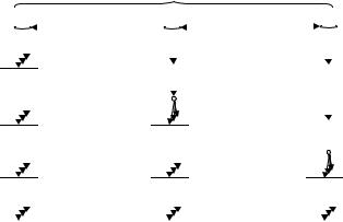
Figure 11.6 Illustration of data flow through RLC, MAC, and L1 in the network side for different transmission scenarios.
to DCH or HS-DSCH, is used). One MTCH is configured for each MBMS service and each MTCH is mapped to one FACH transport channel. The S-CCPCH is the physical channel used to carry one (or several) FACH transport channels.
The RLC for MTCH is configured to use unacknowledged mode as no RLC status reports can be used in point-to-multipoint transmissions. To support selective combining (discussed in Section 11.1.1), the RLC has been enhanced with support for in-sequence delivery using the RLC PDU sequence numbers and the same type of mechanism as employed in MAC-hs (see Chapter 9). This enables the UE to do reordering up to a depth set by the RLC PDU sequence number space in case of selection combining.
In Figure 11.6, an example of the flow of application data through RLC, MAC, and physical layer is illustrated. The leftmost part of the figure illustrates the case of point-to-point transmission, while the middle and rightmost parts illustrates the case of point-to-multipoint transmission using the MTCH. In the middle part, one RLC entity is used with multiple MAC entities. This illustrates a typical situation where selection combining is used, where multiple cells are loosely time aligned and the same data may be transmitted several TTIs apart in the different cells. Finally, the rightmost part of the figure illustrates a typical case where soft combining can be used. A single RLC and MAC entity is used for transmission in multiple cells. To allow for soft combining, transmissions from the different cells need to be aligned within 80.67 ms (assuming 80 ms TTI).