

Учебное пособие 1751
.pdf1)ionosphere
2)stratosphere
3)absorption
2.Radio signals radiate or .............. from a transmitting antenna.
1)extend
2)allocate
3)propagate
3.The D layer reaches maximum ionization when the sun is at the zenith and ................ quickly toward sunset.
1)dissipates
2)spreads
3)strikes from
4.We characterize a radio wave in terms of its ............... and frequency.
1)amplitude
2)modulation
3)absorption
Task 35. Some acronyms are given. Try to find the meaning of each of them using a glossary.
Example: RMS – Root Mean Square
HF band, BLOS, SID, FOT, MUF, LUF, FEC, FSK, BER
Task 36. Choose the best variant to complete each sentence using acronyms:
Pattern: Amplitude, which is measured in volts is usually expressed by engineers in terms of an average value called root mean square.
– RMS – FOT – LUF
See keys at the end of the Activity V.
1.Why is the ionosphere in HF Radio? Well, this blanket of gases is like nature’s satellite, actually making most (BLOS, HF, FOT).
2.Class of unpredictable phenomena known as (SID, LUF, BER) can affect High Frequency Communications.
3.(HF, FSK, MUF) frequencies were called short wave because their
31
wavelengths (10 to 100 meters) were shorter than those of commercial broadcast stations.
4.The highest possible frequency that can be used to transmit over a particular path under given ionospheric conditions is called the (MUF, FOT, LUF).
5.The frequency at which the signal is completely absorbed by the ionosphere is called the (LUF, FEC, FSK).
DISCUSSION
Working with a partner do the following tasks. Share your ideas with the whole group.
1.Can you name the main principles of radio communication?
2.Use the figure 8 and give explanations about the advantages of FEC over BER.
3.Discuss the problems of radio wave propagation in different layers of the ionosphere.
4.Discuss the properties of a radio wave.
5.Find and solve the problems of the radio frequency spectrum with the help of figure 2.
6.Share your opinion on high band extension.
Keys: 1. BLOS; 2. SID; 3. HF; 4. MUF; 5. LUF
OUTCLASS ACTIVITY
Task 37. Read the following text and give the written translation using your dictionary and paying attention to Active and Passive Constructions.
TEXT 1:
ADAPTIVE RADIO TECHNOLOGY
1. The constantly changing properties of the ionosphere, as well as random noise and interference, cause disruptions in HF communications.
In the past, a skilled radio operator was required to establish communications and to continually adjust operating parameters. Today, this function is fully automatic. Harris RF Communications provides adaptive radio systems, pioneered in the early ’80s, that can react rapidly
32
to changing propagating conditions and use feedback from Real Time Channel Evaluation (RTCE) techniques to select frequencies, adjust data rates, or change modulation schemes. Two of the many adaptive processes are Automatic Link Establishment (ALE) and Link Quality Analysis (LQA). Because of Harris’ previous experience with adaptive radio technology, the company was asked to become a member of the United States Military Standard Committee to develop the ALE standard.
2.ALE is a technique that permits HF radio stations to call and link on the best HF channel automatically without operator assistance. Harris pioneered the manufacture of adaptive communications equipment with AUTOLINK. In addition, Harris is a leader in the development of advanced ALE techniques that comply with MIL-STD-188-141A and FED- STD-1045A.
3.Typically, ALE systems make use of recently measured radio channel characteristics (LQA data) stored in a memory “matrix.” The system works much like a telephone in that each radio in a network is assigned an address (ID). When not in use, each radio receiver constantly scans through its assigned frequencies, listening for calls addressed to it.
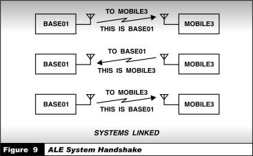
4. To reach a specific station, the caller simply enters an ID just like dialing a phone number. The radio consults its LQA matrix and selects the best available assigned frequency. It then sends out a brief message containing the ID of the destination. When the receiving station “hears” its address, it stops scanning and stays on that frequency. The two stations automatically conduct a “handshake” to confirm that a link is established
33

and they are ready to communicate (figure 9). The receiving station, which was completely silent, will typically emit a ringing signal to alert the receiving operator of an incoming call. At the conclusion of the call, one of the stations “hangs up”, a disconnect signal is sent to the other station, and they each return to the scanning mode.
5.An HF communications system has a number of channels assigned to it. A system incorporating LQA capability selects the best channel. Here’s how it works in an adaptive system.
6.At prescribed intervals, a station in a network will attempt to link on each of its assigned frequencies and measure the signal quality on each linked frequency. These quality scores are stored in a matrix. When a call is initiated, the radio checks its “memory” to determine the best quality frequency for the call to the desired station. It then attempts to link on that frequency. If the link cannot be established, it will try again on the next best frequency, and so on, until a link is established.
7.Figure 10 shows a simplified LQA matrix for station BASE01. The channel numbers represent programmed frequencies, and the numbers in the matrix are the most recent channel-quality scores. Thus, if an operator wanted to make a call from BASE01 to MOBILE3, the radio would attempt to call on channel 05, which has the highest LQA score.
8.When making multi-station calls, the radio selects the channel with the best average score. Thus, for a multi-station call to all the addresses in the matrix, channel 04 would be selected.
34
9. Adaptive radio technology is further enhanced by the use of computer controllers, which permit modem data rate selection based on channel conditions, optimum antenna choice, automatic adjustment of transmitted power level, automatic nulling and elimination of interfering signals, and selection of modem modulation and coding schemes. The benefit is that these adaptive schemes are largely automatic and improve communications without operator intervention. Thus, the requirement for an operator with high technical knowledge has been significantly reduced.
Task 38. Read the text 2 and sum it up:
TEXT 2:
HF SYSTEMS AND APPLICATIONS
1.HF radio offers a unique combination of cost, effectiveness and versatility for long-haul communications. In recent years, computer technology and high-speed digital signal processing have enhanced the performance and reliability of HF communications systems, resulting in reduced operator involvement in establishing HF communications circuits.
At the same time, new technology has dramatically reduced the size and weight of HF radio equipment. Diverse capabilities, which formerly required separate pieces of equipment, are now combined and embedded into the radio transceiver itself.
2.Harris Corporation, RF Communications Division, designs, manufactures, and installs turnkey radio communications systems for worldwide government, military, and commercial markets. Here are some examples of how these HF systems come together in a modern communications network to meet complex communications needs.
3.Figure 11 shows a typical secure HF data transmission system, which can be used whenever it is necessary to transfer data securely between two points. The serial modem, which uses FEC coding, also provides real-time channel equalization and data interleaving for protection against fading, and automatic excision filters remove interference from up to four sources. The transmit modem data rate adjusts to the terminal data rate and is selected on the basis of an LQA (estimate of channel quality). The amount of coding (redundancy) used in the FEC varies as a function of the selected modem data rate. Thus, if poor channel quality is predicted, a relatively low data rate and a more powerful FEC code will be designated.
35

4. A country-wide HF data communications system, which provides economical, long-range communications, is shown in Figure 12.
The HF data communications system links a fixed central communications center and 12 subordinate stations located throughout the country. The system incorporates an ALE capability that offers fully automatic operation with unattended processing of incoming messages. Each subordinate station has additional HF and VHF radios that provide voice and data communications to mobile stations in its vicinity. In the data communications mode, an ARQ message protocol is used for error
36
detection and correction. The central station is a fixed installation with separate transmit and receive control sites. Intersite communications and control are via microwave or a landline link.
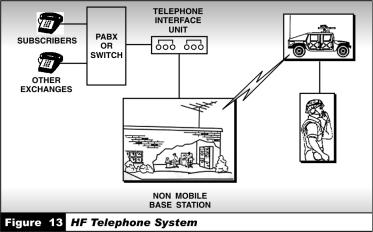
5. An HF radio link can extend the reach of a telephone network, as shown in Figure 13. The system operates much like the cordless telephone widely used in homes today, but covers hundreds of thousands of miles using HF radio. The HF telephone system enables users to place calls to and from mobile radio transceivers into the commercial switched telephone network or private subscriber telephone lines.
6.Calls from the field can be placed over HF, VHF, or UHF to anywhere in the world through the base station telephone switch or exchange. To initiate a call, the user enters a telephone number just as if the Remote Access Unit (RAU) were a telephone set connected directly to the base station telephone exchange.
7.At this point, the number dialed is transmitted through the RAU to the Telephone Interface Unit (TIU). As the TIU dials the digits and the telephone rings, call progress tones are heard by the mobile operator. In order to contact anyone in the field, a telephone user dials a telephone number (or the extension) to which the TIU is connected – from anywhere in the world. The call is automatically answered by the TIU and the user is connected directly with the field radio.
37

II. ELEMENTS OF RADIO SYSTEMS
CLASS ACTIVITY
ACTIVITY 1
Text 2.1: NOISE AND INTERFERENCE
Grammar: WAYS OF EXPPRESSING SUBJECT
Task 39. Study the ways of expressing subject in the English Sentence. Translate the sentences.
WAYS OF EXPRESSING |
|
|
|
|
|
SUBJECT |
|
|
EXAMPLE |
|
|
(PARTS OF SPEECH) |
|
|
|
|
|
|
|
||||
1. A noun (in the common |
Receiver noise comes from both |
||||
case) |
sources. |
|
|
||
|
|
|
|
|
|
2. A Gerund, a gerundial |
Combating noise and interference |
||||
phrase or construction. |
|||||
includes boosting the effective radiated |
|||||
|
|||||
|
power and providing a means for |
||||
|
optimizing up. |
|
|
||
|
|
|
|
|
|
3. A substantivised adjective |
The |
wireless |
is disabled |
or not |
|
or participle. |
associated. |
|
|
||
|
|
|
|||
|
|
|
|
|
|
4. An infinitive, infinitive |
To reduce collocation interference apply |
||||
phrase or constructions. |
|||||
carefully orienting antennas. |
|
||||
|
|
||||
|
|
|
|
|
|
5. “It” as a subject of the |
It |
may be |
continuous |
(constant |
|
sentence. |
|||||
transmitting) or look-through (transmit |
|||||
|
|||||
|
and when signal to be jammed is |
||||
|
present). |
|
|
||
|
|
|
|
|
|
38
Task 40. Find the subject in the English sentence. Pay attention to the ways of expressing it in the Russian equivalent.
1. External noise levels greatly |
Уровни внешних шумов сильно |
exceed internal receiver noise |
превышают внутренние шумы |
over much of the HF band. |
приемника на большей части |
|
ВЧ-диапазона. |
2. Lighting is the main natural |
Молния – это основной |
source of noise |
(природный) источник шума. |
|
|
3. It may be a deliberate attempt |
Это может быть |
on the part of an adversary to |
предумышленной попыткой |
disrupt an operator's ability to |
злоумышленника помешать |
communicate. |
оператору вести связь. |
4. Grounding and shielding of the |
Заземление и экранирование |
radio equipment and filtering of AC |
радиооборудования и |
power input lines are techniques |
фильтрация входных линий |
used by engineers to suppress |
переменного тока – это |
EMI. |
способы, используемые |
|
инженерами для подавления |
|
электромагнитных помех. |
|
|
5. It is uniformly distributed over |
Он равномерно |
the HF spectrum, but does not |
распространяется по ВЧ- |
affect performance below 20 MHz. |
спектру, но никак не влияет на |
|
производительность ниже 20 |
|
МГц. |
|
|
Task 41. Study the sentences where the following words and word combinations are used.
1. Receiver noise and interference – шум и интерференция приемника
Receiver noise and interference come from both external and internal sources.
2. Signal-to-noise ratio (SNR) – отношение сигнал/ шум
Signal quality is indicated by signal-to-noise ratio (SNR), measured in decibels (dB).
3. Boosting – повышение, увеличение
39

Boosting the effective radiated power is in one of the techniques used by engineers in combating noise and interference.
4. Man-made noise – индустриальная помеха, искусственно созданный шум
Power lines, computer equipment, industrial and office machinery produce man-made noise.
5. Grounding and shielding – заземление и экранирование
Grounding and shielding of the radio equipment are important for EMI suppression.
Task 42. Match up the words with the definitions.
noise |
jam |
|
|
interference |
earth fault |
|
|
boosting |
to choose |
|
|
grounding |
cancellation |
|
|
shielding |
artificial; industrial |
|
|
to select |
scaling up; increase, raise |
|
|
suppression |
shading; caging |
man-made |
static at radio wavelengths |
|
|
|
|
Task 43. Skim the text from Task 44 and find key sentences in each paragraph.
Task 44. Read the following text carefully and try to understand the content of the text.
TEXT 2.1:
NOISE AND INTERFERENCE
1. Receiver noise and interference come from both external and internal sources. External noise levels greatly exceed internal receiver noise over much of the HF band. Signal quality is indicated by signal-to-noise ratio
40