

Art.-no.: 2.540037 Rev.: a
|
Service Handbook |
System Settings |
4 |
A"#$0$ |
Software |
4.5 |
|
|
|
|
|
4.5Software
|
|
|
|
|
When software is selected, two option are given for update Software (new software) |
|
|
|
|
|
|
and upgrade Software (activating options). See details in the following procedures |
|
COMM |
SOFTWARE |
BASE |
EXIT |
|||
SETUP |
TEST |
INIT. |
||||
|
|
|
||||
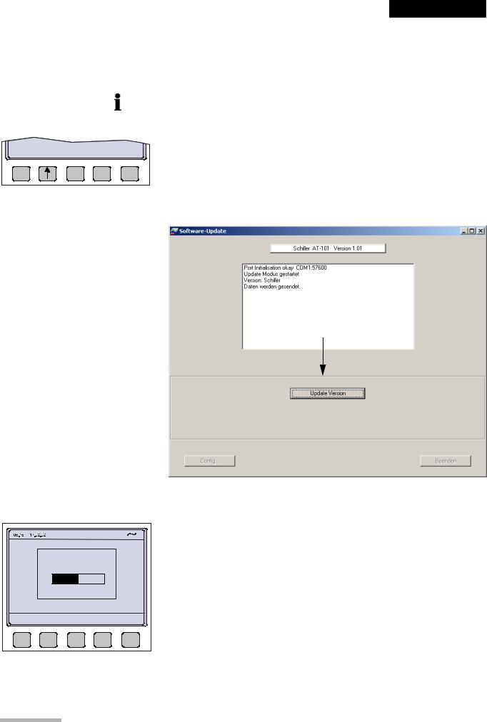
4.5.1Preparing serial communication for software update
•Requirement to run Install.exe file: Win NT4, Win 98, Win 2000, Win XP.
•Connect the AT-101 to the mains
•Do not power off during update!
•RS-232 cable
•Download software Install•AT101xxx.exe
1.Connect the RS-232 cable to the connector (1) on the back of the device.
2.Connect the DB 9 connector to your PC RS-232 Com port.
Install the software on your pc with a double click to the Install•AT101.exe file.
1.Start the program AT101Swup
2.Press button config (1).
3.Select the com port (2) you have choosen to download the software.
4.Select baudrate = auto.
2
1
Fig. 4.1 Software update
Page 29
4 |
System Settings |
|
4.5 |
Software |
A"#$0$ |
|
|
|
4.5.2Update software
• Make sure the device is powered by mains.
|
|
1. |
Switch on the device. |
|
|
|
2. |
Select menu SETUP > SYSTEM SETTINGS >TEST AND INFO |
|
UPGRADE UPDATE |
EXIT |
|||
|
|
3.Press button Program Update.
4.Press the button “Download” on the dialogue box of your PC.
AT-101 |
1.01 |
CANCEL |
Fig. 4.2 Software dialogue box
5.The bargraph shows the progress of the download. After downloading, the device will restart automatically.
6.Check the Software version in the menu TEST and INFO.
Art.-no.: 2.540037 Rev.: a
Page 30

|
Service Handbook |
System Settings |
4 |
A"#$0$ |
Software |
4.5 |
|
|
|
|
|
4.5.3Upgrade to a new option
COMM |
SOFTWARE |
BASE |
EXIT |
||
SETUP |
TEST |
INIT. |
|||
|
|
UPGRADE UPDATE |
EXIT |
AT-101 |
|
|
V1.0 Ctm |
RI5.73 |
|
070.1234567 |
26.09.2003 |
|
Copyright } 2002-03 |
|
|
SCHILLER AG, Switzerland |
|
|
|
0 |
1 |
|
BACK |
|
Use the upgrade function to activate any available software options (e.g. Measurement). To activate new options in the AT-101, a code must be entered. This code must be obtained from SCHILLER.
To install software option proceed as follows:
1.Enter the TEST and INFO screen
SETUP > SYSTEM SETTINGS >TEST AND INFO
2.Select SOFTWARE.
3.Select UPGRADE.
4.Enter the upgrade code 6 digits.
When the correct code is entered, acceptance of the code is indicated by a series of beeps. The option can be used immediately.
The number of unsuccessful trials will be displayed on the right side of the code box (1).
Art.-no.: 2.540037 Rev.: a
!More than 10 attempts to enter the incorrect code blocks the unit.
Page 31

4 |
System Settings |
|
4.5 |
Software |
A"#$0$ |
|
|
|
4.5.4Default Settings
COMM |
SOFTWARE |
BASE |
EXIT |
||
SETUP |
TEST |
INIT. |
|||
|
|
To reset the unit to the base default settings, press the BASE INIT softkey. As the unit resets to the default values a message is briefly displayed on the LCD. The base settings (Defaults) are given on the following page.
Unit Defaults Table
Settings |
Standard |
With Interpretation |
|
Language |
As set |
As set |
|
Auto Format 1 |
ECG: 25mm/s, short (o) |
ECG: 25mm/s, short (o) |
|
Internal |
Rhythm Leads V1 |
Rhythm Leads V1, II |
|
|
|
|
|
|
|
MECG: 2x6 (50mm/s + 1) |
|
|
|
Measurements: Suppressed (-) |
|
|
|
|
|
|
|
Marks: Enabled (+) |
|
|
|
Interpretation: Enabled (+) |
|
|
|
|
|
Auto Format 2 |
ECG: 25mm/s, Long (ooo) |
ECG: 25mm/s, long (ooo) |
|
external |
Rhythm Leads V1 |
Rhythm Leads V1, II |
|
|
|
|
|
|
|
MECG: none |
|
|
|
Measurements: Suppressed (-) |
|
|
|
|
|
|
|
Marks: Enabled (+) |
|
|
|
Interpretation: Enabled (+) |
|
|
|
|
|
Filter |
Baseline 0.05Hz |
Baseline 0.05Hz |
|
|
Mains Filter 50Hz (60Hz) |
Mains Filter 50Hz (60H |
|
|
|
|
|
|
Myogram off at power up |
Myogram off at power up |
|
|
Myogram 35Hz, OFF |
Myogram 35Hz, OFF |
|
|
|
|
|
|
SBS OFF (-) |
SBS OFF (-) |
|
|
SSF OFF (-) |
SSF OFF (-) |
|
|
|
|
|
Interpretation |
|
Sensitivity low (-) |
|
Settings |
|
||
|
|
||
|
|
Age: <= 30 (-) |
|
|
|
|
|
|
|
Abnormal ECG Not Print |
|
|
|
Unconf. Report Print (+) |
|
|
|
|
|
|
|
Thrombolysis OFF (-) |
|
Leads |
Sequence Standard (S) |
Sequence Standard (S) |
|
|
|
|
|
|
Signals Sequential |
Signals Sequential |
|
|
Autom. Centering ON (+) |
Autom. Centering ON (+) |
|
|
|
|
|
|
Rhythm On (+) |
Rhythm On (+) |
|
|
V4-9 On (+) |
V4-9 On (+) |
|
|
|
|
|
|
V5r Off (-) |
V5r Off (-) |
|
|
V6r Off (-) |
V6r Off (-) |
|
|
|
|
|
|
Nehb DAJ Off (-) |
Nehb DAJ Off (-) |
|
General |
Storage mode manual |
Storage mode manual |
|
|
|
|
|
Memory and |
Baud rate 57600 bps |
Baud rate 57600 bps |
|
Communication |
|||
|
|
||
|
Trans. mode: line |
Trans. mode: line |
|
|
|
|
Art.-no.: 2.540037 Rev.: a
Page 32
|
Service Handbook |
Care & Maintenance |
5 |
A"#$0$ |
Service Interval |
5.1 |
|
|
|
|
|
Art.-no.: 2.540037 Rev.: a
5Care Z Maintenance
5.1Service Interval
|
|
The device must be serviced in regular intervals. The test results must be document- |
||
|
|
ed and be compared with the values in the accompanying documents. |
||
|
|
Maintenance work not described in this chapter, e.g. battery changes, may only be |
||
|
|
accomplished by a qualified technician authorised by SCHILLER AG. |
||
|
|
The following table gives information about interval and competence of maintenance |
||
|
|
which can be required. |
|
|
|
|
|
||
Interval |
Service |
Responsible |
||
|
• |
Keyboard test |
|
|
Every 6 months |
• |
LED test |
" User |
|
|
• Visual inspection of the unit and cables |
|
||
|
|
|
||
|
• Every servicing of the six month interval |
" By SCHILLER AG author- |
||
Every 12 months |
• Functional tests according to the Service Handbook. |
|||
ised technician |
||||
|
• Electrical safety tests according to IEC 60601-1, Clause 18 and 19 |
|||
|
|
|||
Every 24 months |
• Every servicing of the 6- and 12 months interval. |
" By SCHILLER AG author- |
||
• Every measuring test and calibrations according to the service hand- |
||||
|
|
book. |
ised technician |
|
|
|
|
||
|
|
|
|
|
5.1.1Safety notes
!Danger of electrical shock. When working on a open device connect device always on a isolation transformer.
!Follow the procedures for the prevention of accidents and environmental protection according your national guidelines.
Observe precautions for handling electrostatic sensitive devices when opening the device.
Page 33

5 |
Care & Maintenance |
|
5.2 |
Functional test |
A"#$0$ |
|
|
|
5.2Functional test
Opening of the Device
Whenever a device is opened for repairs or calibration, a functional and Safety Test has to be carried out at the end of the operation.
Required Measurement Equipment
• Safety Tester IEC/EN 60601-1
• Digital Voltmeter 4 Digit 0...200mV ACeff ! 2%
• ECG Simulator (Suggested: Phantom 320 M‚ller Sebastiani)
For the measurement devices specified above, only the requirements necessary for this test are mentioned.
IMPORTANT!
The measurement devices listed above are subject to the instructions according to
ISO 9000 in regards to Test Equipment Control.
5.2.1Internal Sight Control
If the device was opened, the device has to be given a full sight control before it is screwed back together.
Once the sight control has been completed, the device can be closed.
Check following items:
•All printed boards are securely screwed
•Plugs are properly in the socket and secured
•All protective cable (green/yellow) are properly laid out and securely connected to one the earth point (potential equalisation).
•All Cables connection between the individual printer boards are not crushed anywhere or lying on sharp parts (i.e. protective shields). If cables have to be lead passed a sharp part, it is important that they are protected by a special shield
•Isolation foils and shields are built in correctly and are certainly not left out or forgotten (see explosion drawings)
•Check that no loose parts are inside the device by tipping the device, or turning it upside down
5.2.2External Sight Control
Check following items:
•Voltage selector is set correctly
•Fuses according table (see page 45)
•Safety labels are on the device and are readable
•Mechanical condition of the device allows a further safe operation (cracks in the shell, mains cable, etc.).
•there is no soiling which could hamper the safety of the device.
Page 34
Art.-no.: 2.540037 Rev.: a

Art.-no.: 2.540037 Rev.: a
|
Service Handbook |
Care & Maintenance |
5 |
A"#$0$ |
Functional test |
5.2 |
|
|
|
|
|
5.2.3Mains indicator LED test
1.Connect the power cable at the rear of the unit.
5• The mains indicator lamp (6) is always lit when the unit is connected to the mains
|
|
supply. |
|
|
2. |
Switch the unit on. |
|
6 |
• The relevant symbol is displayed on the LCD (7). |
||
3. |
Disconnect the power cable. |
||
|
|||
• The mains indicator lamp (6) switches off and the symbol battery is displayed on the LCD (7).
7
5.2.4Power Supply test
Measuring of unloadand operating current of the device.
1.Connect the multi meter at the power input to measure the current.
2.Check current as follows:
–Unloaded current (device switched off) 35...70 mA
–Operating current (device switched on) 45...85 mA
5.2.5Keyboard test
Check following items:
•Check the keyboard for mechanical damage. If any can be seen, the keyboard is to be replaced.
•Check all function keys for their proper operation. An acoustic confirmation appears whenever a function key is pressed.
•Test the alphabetical keyboard as follows:
–With C device, go to the menu "Edit Interpretation" and test all keys.
–In all other devices, the test is carried out in the menu "Patient Data".
5.2.6LCD Screen test
1.Press the function key FN and the UP/DOWN arrows to adjust screen contrast.
2. Check following:
–The contrast has to be variable from very dark to very light.
–Visually check the screen for spots, or black fields. If such appear, the LCD has to be replaced. The LCD has to be the same shade everywhere. If one side is darker, the background lighting should be checked.
Page 35

5 |
Care & Maintenance |
|
5.2 |
Functional test |
A"#$0$ |
|
|
|
5.2.7Paper Feed
1.Start printer with "MAN PRINT". Press the  key twice.
2.The paper has to stop exactly at the perforation. If this is not the case, control the paper mark comparison.
5.2.8Printer quality test
1.Go to the menu "LEAD TEST" and “MANUAL PRINT ”.
2.Select printer speed 5 mm/s key 7.
3.Press “FN” and “Manual PRINT”. A printout with test curves is executed.
4.Check the blackness for regularity and good readability on the complete print width.
If individual points are missing, the problem is usually with the thermal print head. If the print quality is inadequate, control the electrical / mechanical setting of the print head according to the comparison in this handbook.
Fig. 5.1 Printer quality test
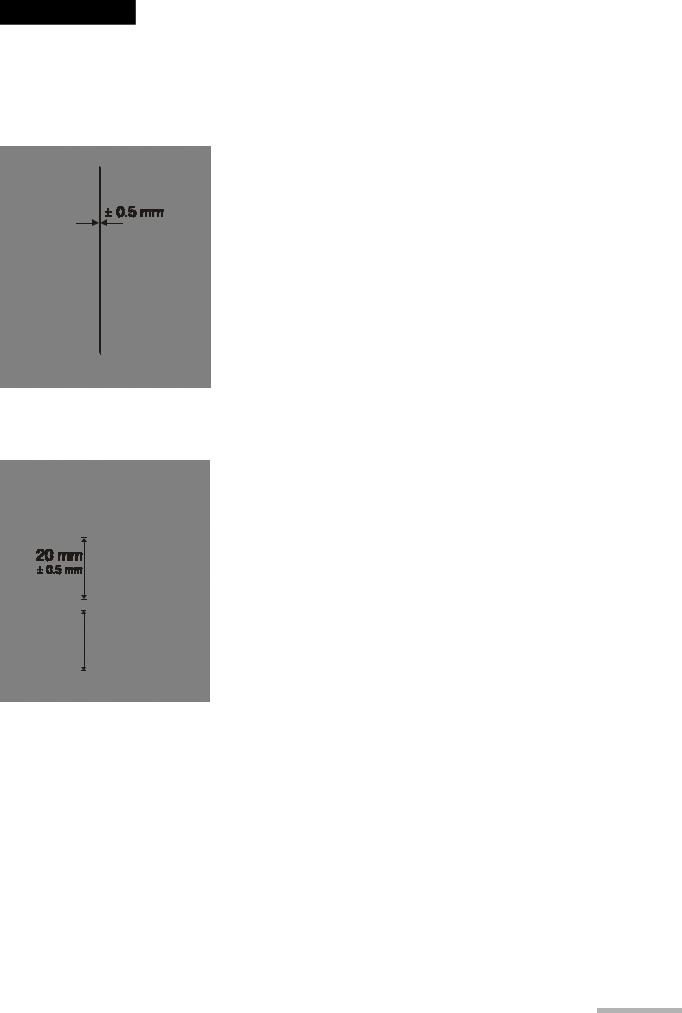
5.2.9Printing Speed
1.Connect the simulator to the ECG device using the patient cable and select a HR of 60 / min. No arrhythmias.
2.Check that the HR shows exactly 60 on the LCD.
3.Set the printing speed to 5 mm/s and press the "MAN START" key. Printout a few pages.
4. Select printing speed 10/25 and 50 mm/s.
5.Check on the 25 mm/s printout if the space between 2 R peaks according to the paper grids. The space should be 25 mm and may not show a difference of more than ! 0.5 mm.
Fig. 5.2 Printer speed test
Page 36
Art.-no.: 2.540037 Rev.: a
|
Service Handbook |
Care & Maintenance |
5 |
A"#$0$ |
Functional test |
5.2 |
|
|
|
|
|
5.2.10Parallelism test
This will test the mechanical adjustment of the print head to the paper grids.
1.Start the manual printout.
2.Press the "1 mV" key.
3.Stop printout and check the parallelism of the print to the paper grid.
– All calibration impulses should be lined up vertically and exactly below one another.
–The maximum deviation may not be more than ! 0.5 square. If the values are outside this tolerance, the mechanical adjustment of the print head has to be corrected.
Art.-no.: 2.540037 Rev.: a
Fig. 5.3 Printer adjustment test
5.2.11ECG amplifier
1.Start the manual printout with 25 mm/s and 20 mm/mV.
2.Press the "1 mV" key
3.Check the amplitude height of the calibration impulse according to the paper grid. It should be 20 mm !0.5 square.
If some values are outside the tolerance, the ECG amplifier has to be replaced.
Fig. 5.4 ECG amplifier
Page 37

5 |
Care & Maintenance |
|
5.2 |
Functional test |
A"#$0$ |
|
|
|
5.2.12ECG lead and patient cable test
ECG AMPLIFIER: |
U el [mV] |
|
|||
Uref+: |
2002 |
|
R |
-517 |
1 |
Uref-: |
2000 |
|
L |
-518 |
|
Udif: |
4001 |
|
C1 |
-520 |
|
Uoff: |
166 |
|
C2 |
-516 |
|
Calib: |
1000 |
|
C3 |
-521 |
|
|
|
|
C5 |
-515 |
|
TPH TEMP: |
23°C |
C6 |
-517 |
|
|
|
|
LEAD TEST |
|||
Eprom: |
623 |
|
|
|
|
|
|
|
|
||
RETURN |
|
|
|
|
MENU |
TEST |
|
|
|
|
|
|
|
|
|
|
|
ECG AMPLIFIER: U el [mV]
Uref+: |
2002 |
R |
4 |
Uref-: |
2000 |
L |
1 |
Udif: |
4001 |
C1 |
3 |
Uoff: |
166 |
C2 |
1 |
Calib: |
1000 |
C3 |
4 |
|
|
C5 |
3 |
|
|
C6 |
2 |
TPH TEMP: |
23°C |
|
|
Eprom: |
623 |
|
|
1.Press “FN” key and Lead test.
2.Disconnect ECG simulator.
3.Check following:
–device beeps 4 time
–all leads (1) are blinking
–Uel for all leads is -350 to -550 mV
4.Connect ECG simulator and setup HR to 60 b/min, no arrhytmias.
5.Check following:
–all leads stops blinking
–Uel for all leads is -15 ...+15 mV
–Udif = 3985 ...4015 mV
–TPH = 18 ...30 °C
6.Press “RETURN TEST”
7.Press  key.
key.
8.Check amplitude and polarity according following printouts.
Fig. 5.5 ECG amplifier
Art.-no.: 2.540037 Rev.: a
Page 38