NOTE Packets with CoS 5 are always placed in the strict-priority or egress expedite queue, but that queue cannot be used until it is enabled. Use the following interface configuration command to enable the strict-priority queue:
Switch(config-if)# priority-queue out
Avoiding Congestion by Using Tail Drop
For standard tail-drop behavior, WRR must be disabled on an interface. After the egress queue fills, tail drop causes newly queued packets to be dropped instead. This occurs at the 100 percent mark of the queue. Normally, tail drop should not be used because it can adversely affect the network performance of TCP sessions.
NOTE The strict-priority queue is never a candidate for WRR-based queue scheduling. In the event that the queue fills to capacity, new packets will be dropped, following standard tail-drop behavior.
To enable tail-drop operation for an egress queue, use the following interface configuration command:
By default, each switch interface has WRED enabled. If tail drop is being used instead, WRED has been disabled. To revert back to WRED, it must be re-enabled. Note that WRED is used on a perqueue basis and that it must be enabled on each of the interface’s queues individually. To enable WRED for a specific queue number, use this interface configuration command:
WRED keeps two thresholds per queue for most types of interfaces—a minimum threshold and a maximum threshold. If the queue level is below the minimum, WRED cannot drop any packets. While the level is between the minimum and maximum values, WRED is allowed to randomly drop packets at a rate proportional to the queue level. When the queue level rises above the maximum threshold, all new packets will be dropped. To set the WRED thresholds, use the following interface configuration command:
By default, queue 1 (the lowest-priority standard queue) has a minimum threshold of 0 and a maximum threshold of 40 percent. Queue 2 (the next-higher priority standard queue) has a minimum of 0 and a maximum of 100 percent.
The low-priority standard queue will always be susceptible to random drops (minimum is 0 percent). When the low-priority standard queue fills to 40 percent, all new packets will be dropped. The higher-priority queue is also susceptible to random drops (its minimum is also 0 percent); however, this queue’s level must reach 100 percent before all packets are dropped.
NOTE The strict-priority queue is never a candidate for WRED-based drops. Instead, all packets queued are guaranteed to be delivered. Only when the queue fills to capacity will new packets be dropped, following standard tail-drop behavior.
A QoS Configuration Example
QoS configuration within a single switch can be confusing and complex. To properly implement QoS policies in a common QoS domain (your entire network, for example), you must configure the QoS policies on each and every switch. This example is designed to help solidify the many topics presented in this chapter so that you can identify trust boundaries and configure QoS in a logical fashion.
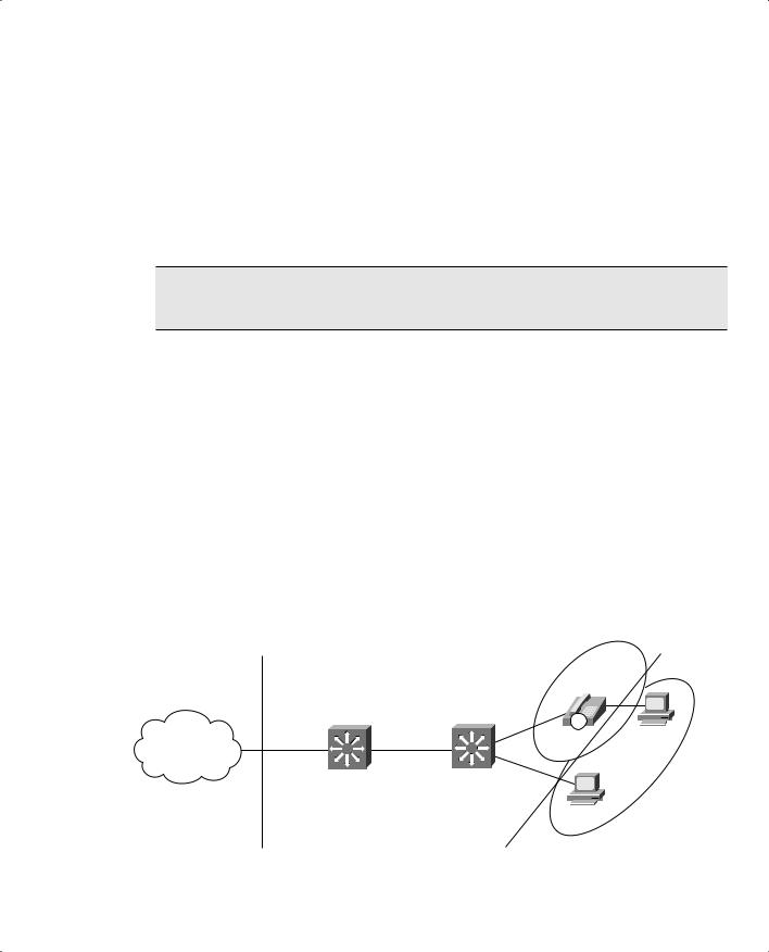
Figure 17-2 shows a simple network consisting of two Catalyst multilayer switches. Catalyst A sits at the edge of the QoS domain, where this network joins another “public” network. Catalyst B, on the other hand, sits inside the QoS domain and interfaces to some end user devices. One port connects to a user PC and another port connects to a Cisco IP Phone. Another user PC connects to the IP Phone’s data port.
Figure 17-2Network Diagram for the QoS Example
fa0/1
Public
gig2/1
gig2/2
gig0/1
Network
fa0/2
Cisco
IP Phone
IP
VLAN 200
PC
VLAN 100
Catalyst A
Catalyst B
PC
Untrusted
Untrusted
Trust
Trust
Boundary
Boundary
418 Chapter 17: DiffServ QoS Configuration
To configure QoS in this network, you must first define the QoS domain, where QoS information will be known and trusted. The edge of this domain lies at the points where QoS information is no longer trusted—at the trust boundaries. In Figure 17-2, a trust boundary exists where Catalyst A connects to the public network. Another trust boundary exists where Catalyst B meets the end users. The user PC should not be trusted because it might have applications that try to spoof or elevate the QoS information to bogus values in an effort to get better service. The IP Phone itself can be trusted because it is just another network device that can be configured and controlled. However, it lies at another trust boundary where another user PC connects. (The details of QoS trust with an IP Phone are discussed in Chapter 18 “IP Telephony.”)
Configuring QoS Trust
First, you should configure Catalyst A for its trust boundary on interface GigabitEthernet 2/1. Any QoS information coming from the public network should be untrusted because you have no control over the values being sent or who is sending them. You can use the following configuration commands to accomplish this:
mls qos
interface gigabitethernet 2/1 no mls qos trust
Notice that the first command enabled QoS on the switch. Do not forget this important first step. The interface is configured to consider all inbound QoS information as untrusted. As a result, any inbound CoS (assuming this interface is a trunk) and DSCP values are set to 0, the default.
Notice also that this interface configuration command is not necessary because all switch ports are configured as untrusted by default. This also means that all of Catalyst A’s ports that are inside the QoS domain (the trusted side) will not trust QoS information that should be known and valid. Do not forget to configure the trusted ports—everyswitch port that connects to another switch inside your network. If you configure QoS consistently throughout your network, you can always trust the QoS information as it moves about.
For this network, inbound DSCP information will be used as the trusted quantity. This is possible because all the switches are multilayer switches and can understand and work with DSCP as an IP or Layer 3 quantity. Catalyst A’s GigabitEthernet 2/2 interface is then configured as a trusted port with the following configuration commands:
interface gigabitethernet 2/2 mls qos trust dscp
A QoS Configuration Example 419
NOTE Remember that only inbound QoS information can be trusted. Outbound QoS information is simply sent on to the next-hop switch or router where it will be evaluated against another trust relationship there. Any DSCP information that Catalyst A accepts from the internal network will also be forwarded out toward the public network on interface GigabitEthernet 2/1. Does the network on the other side of the QoS boundary have to accept or trust the QoS information you send? Only if it wants to. It is up to the network administrators on that end to decide what sort of trust relationship to configure on their switches.
Next, you must configure Catalyst B for its trust boundary. Interface GigabitEthernet 0/1 is on the inside or trusted side of the QoS domain. Therefore, DSCP information can be trusted:
mls qos
interface gigabitethernet 0/1 mls qos trust dscp
Interface FastEthernet 0/2 connects to an end user’s PC and should not trust any QoS information. The following configuration commands set the trust boundary and force any inbound CoS and DSCP values to 0 (by default):
interface fastethernet 0/2 no mls qos trust
Interface FastEthernet 0/1 presents an interesting case. Here, a Cisco IP Phone is connected, transporting Voice over IP (VoIP) traffic, as well as normal data from the attached PC. As Chapter 18 discusses, a Catalyst switch can detect an IP Phone via Cisco Discovery Protocol (CDP) and can instruct the phone to extend a trust boundary to its auxiliary data port. The voice traffic from the phone should be implicitly trusted because the phone is both a Cisco device and a small switch that can be configured and controlled.
The PC connected to the phone, however, should normally be untrusted and have all inbound CoS values set to 0. This is mentioned here to show how trust boundaries also exist at any connected IP Phones. The following configuration commands for the phone trust boundary are fully explained in Chapter 18:
In this example, suppose you need to make sure some types of traffic receive premium service within your network. These types of traffic are classified at the QoS domain boundary, at Catalyst A. HTTP traffic from a server at 10.1.1.1 is considered to contain important, time-critical market data for your
420 Chapter 17: DiffServ QoS Configuration
business. Any virtual private network (VPN) traffic using the IP Security (IPSec) protocol is also considered to carry encrypted data to and from your business partners and remote sites.
First, you must configure a class map to match the HTTP and IPSec traffic. Use an extended access list to identify TCP port 80 (HTTP), while using the NBAR feature to identify IPSec packets. Configure the class map on Catalyst A with the following commands:
ip access-list extended MarketWWW permit tcp host 10.1.1.1 any eq 80
class-map GoodTraffic match-any
match access-group name MarketWWW match protocol ipsec
So far, the idea is to classify the time-critical, very important, or “good” traffic so that a QoS policy can guarantee better service. Sometimes, classifying nuisance or “bad” traffic so that it can be given a lower-level service migt also be necessary. In certain cases, you might choose to drop this type of traffic altogether. Lowering the level of service prevents undesirable traffic from using the network resources needed for more important traffic.
For this example, peer-to-peer file sharing traffic generated by the KaZaA version 2 applications is considered to be unrelated to your business. It is tolerated for the benefit of the employees, but it should receive only “best effort” service. Define a class map on Catalyst A to identify this type of traffic with the following commands:
class-map BadTraffic match-any match protocol kazaa2
Configuring a QoS Policy to Act on Classified Traffic
Now that class maps have been configured to classify or identify specific traffic, some action should be performed to adjust the QoS parameters. This makes up the actual QoS policy, which is defined as a policy map. First, traffic classified by the GoodTraffic class map is given a DSCP value of AF21 so that other switches know to provide good delivery service. Anything classifed by the BadTraffic class map is given a DSCP value of 0, where only “best effort” or default delivery service is requested.
After the policy map is configured, it is applied to an interface in the inbound direction. This classifies and marks traffic as it is received, at the QoS boundary. The policy map is configured on Catalyst A and applied with the following commands:
policy-map MyPolicy class GoodTraffic
set ip dscp af21 class BadTraffic
set ip dscp 0 interface gigabitethernet 2/1
service-policy MyPolicy in
A QoS Configuration Example 421
Egress Queue Tuning
After packets have been classified and marked, you should also consider how the QoS information will be used to queue and schedule packet delivery. In this example, DSCP values AF21 (18) and 0 have been used to mark traffic. In addition, Voice over IP (VoIP) packets associated with the IP Phone on Catalyst B can be expected to have DSCP values AF31 (26) and EF (46). (Chapter 18 discusses this in more detail.) All other applications will have their packets marked to DSCP 0, as a result of the trust boundaries configured throughout the network.
At a minimum, you should look at how the known DSCP values will be mapped to CoS values as packets are sent to the egress queues. CoS is always used to decide how packets are queued and scheduled for transmission. In the default state, before any further configuration is done, the DSCP- to-CoS map looks like Table 17-5.
Table 17-5Default DSCP-to-CoS Value Mappings
DSCP
0-7
8-15
16-23
24-31
32-39
40-47
48-55
56-63
Default
AF10-AF13
AF20-AF23
AF30-AF33
AF40-AF43
EF
Internetwork
Network
Control
Control
CoS
0
1
2
3
4
5
6
7
GoodTraffic packets (DSCP 18) are mapped to CoS 2, BadTraffic packets (DSCP 0) are CoS 0, and VoIP packets (DSCP 26 and 46) become CoS 3 and 5, respectively.
After the CoS values are mapped, they are used to determine into which egress queue each packet will be placed. By default, all switch ports have WRED enabled. For an egress port with a 1p2q2t queueing strategy, the following scheduling occurs:
■CoS 0 and 1: Standard queue 1, threshold 1
■CoS 2 and 3: Standard queue 1, threshold 2
■CoS 4: Standard queue 2, threshold 1
■CoS 6 and 7: Standard queue 2, threshold 2
■CoS 5: Always sent to the strict-priority queue
Assume this is an acceptable scheduling configuration, as CoS 3 will be serviced before CoS 2, which will be serviced before CoS 0, and so on. CoS 5, used for the VoIP voice bearer packets, will always be sent to the strict-priority queue. That queue is, by definition, always serviced before any other queue. Indeed, that sounds reasonable for this example network. No other configuration should be necessary, right?
422 Chapter 17: DiffServ QoS Configuration
Actually, the default condition for every switch port is to disable the strict-priority or expedite egress queue. That is not what you need at all—the voice traffic having CoS 5 will be sent to a standard queue to contend with other less time-critical traffic. If you expect to use the strict-priority queues, do not forget to enable them. The example configuration concludes with the following configuration commands on Catalyst A:
interface range gigabitethernet 2/1 – 2 priority-queue out
Catalyst B receives the following configuration commands:
interface gigabitethernet 0/1 priority-queue out
interface range fastethernet 0/1 – 2 priority-queue out
Verifying and Troubleshooting QoS
You can display information about many aspects of QoS on a Catalyst switch. Use the information in Table 17-6 to determine which command is useful for a particular situation.
Table 17-6Commands to Display Information About QoS on a Catalyst Switch
Task
Command Syntax
Verify QoS trust settings on an
show mls qos interface type mod/num
interface.
Verify egress queueing on an
show mls qos interface type mod/num queueing
interface.
Verify QoS settings only on a
show queueing interface type mod/num
Catalyst 6500 interface.
View all QoS parameter mappings.
show mls qos maps
The show mls qos interface command shows the following information about an interface:
■QoS trust (if any) configured on the interface
■Default CoS value (if any) used to override inbound CoS
■DSCP mutation map
■QoS trust extension to a connected Cisco IP Phone
Verifying and Troubleshooting QoS 423
Example 17-1 provides sample output from the show mls qos interface command.
Example 17-1show mls qos interface Command Output
Switch# show mls qos interface gigabitethernet 0/1
GigabitEthernet0/1 trust state: trust cos trust mode: trust cos COS override: dis default COS: 0
The show mls qos interface queueing command shows the following information about an interface:
■Current state of the strict-priority (expedite) queue
■WRR transmit queue weighting (bandwidth)
■Egress queue ratios (qid-weights)
■Egress queue scheduling (CoS-to-queue mapping)
Example 17-2 shows sample output from the show mls qos interface queueing command.
Example 17-2show mls qos interface queueing Command Output
Switch#
show mls qos interface gigabitethernet 0/1 queueing
GigabitEthernet0/1
Egress expedite
queue: dis
wrr bandwidth weights:
qid-weights
1
- 25
2
- 25
3
- 25
4
- 25
Dscp-threshold map:
d1 : d2 0 1 2 3 4 5 6 7 8 9
---------------------------------------
0
:
01
01
01 01 01
01 01 01
01
01
1
:
01
01
01 01 01
01 01 01
01
01
2
:
01
01
01 01 01
01 01 01
01
01
3
:
01
01
01 01 01
01 01 01
01
01
4
:
01
01
01 01 01
01 01 01
01
01
5
:
01
01
01 01 01
01 01 01
01
01
6
:
01
01
01 01
continues
424 Chapter 17: DiffServ QoS Configuration
Example 17-2show mls qos interface queueing Command Output (Continued)
Cos-queue map: cos-qid
0 - 1
1 - 1
2 - 2
3 - 2
4 - 3
5 - 3
6 - 4
7 - 4
Notice from the shaded text that the strict-priority (expedite) queue is disabled. This is the default state for all interfaces, until the strict-priority queue is enabled with the priority-queue out interface configuration command. Example 17-3 provides the same output after the strict-priority queue has been enabled.
Example 17-3show mls qos interface queueing Command Output After Enabling the Strict-Priority Queue
Switch# config term
Enter configuration commands, one per line. End with CNTL/Z.
Switch(config)# interface gigabitethernet 0/1
Switch(config-if)# priority-queue out
Switch(config-if)#^Z
Switch#
Switch# show mls qos interface gigabitethernet 0/1 queueing
GigabitEthernet0/1
Egress expedite queue: ena wrr bandwidth weights: qid-weights
1 - 25
2 - 25
3 - 25
4 - 25 when expedite queue is disabled Dscp-threshold map:
The Foundation Summary is a collection of information that provides a convenient review of many key concepts in this chapter. If you are already comfortable with the topics in this chapter, this summary can help you recall a few details. If you just read this chapter, this review should help solidify some key facts. If you are doing your final preparation before the exam, this summarized information is a convenient way to review the day before the exam.
You can configure a switch to trust the following inbound QoS parameters:
■ CoS (from a trunk)
■ DSCP (from IP headers)
■ IP Precedence (from IP headers)
Table 17-7QoS Trust Configuration Commands
Task
Command Syntax
Enable QoS on a switch.
mls qos
Choose inbound QoS info to trust on an interface.
mls qos trust {cos | dscp | ip-precedence}
Or none at all.
no mls qos trust
Remember the basic structure of modular QoS configuration:
1.Define a QoS class map to classify specific traffic for a policy; define as many class maps as necessary.
2.Define a QoS policy that uses class maps to identify traffic; the policy also contains actions with each class map that will be taken on classified traffic.
3.Apply the QoS policy to an interface. One policy can be applied to an inbound traffic flow and one to an outbound traffic flow.